
Abstract
This paper provides the main concept of reactive power compensation onboard ship electrical energy systems mainly as a retrofitting means towards assisting the generator plant and improving the ship efficiency in terms of fuel consumption and emissions. The alternative means are presented and discussed via the support of actual case studies.
1. Introduction
The ship electrical energy system is an autonomous system comprising a limited number of generators and a large number of loads, the majority of which consist of asynchronous motors. From the electrical energy balance point of view, the generators must be rated at the ship design stage to meet all energy demands, namely in terms of active power (in W) and reactive power (in VAr). However, as the electric load analysis performed often only covers the demands in terms of active power (Prousalidis Citation2011), it is likely that problems are encountered with meeting the reactive power demands. This is why it has been proposed in previous work (Prousalidis Citation2011; Prousalidis & Kourtesis Citation2014) that, at the design stage, the electric load analysis should take into account the reactive power too.
This paper, however, deals with resolving reactive power problems in existing vessels. In addition, it is shown that this action can result in increased system loadability and an improvement in the ship's efficiency interpreted as the reduction of active power losses leading, in turn, to a reduction of fuel oil consumption and an improvement in the ship's environmental footprint.
To this end, alternative retrofitting measures are presented and analysed. Thus, in addition to synchronous generators, other components like synchronous condensers, capacitor banks and thyristor-controlled combinations of reactors and capacitors are discussed. The discussion is enriched by actual ship case studies.
2. Background: the meaning of reactive power
Unlike DC, where the power is the product of voltage and current (this power can be used to produce mechanical work), in AC this lagging is also introduced via the power factor. The power factor is a means of showing which portion of the product (voltage × current) can be used to produce mechanical work (like in the DC case). The values of the power factor are in the range of 0 to 1. Thus the power is further diversified into:
Active power (the so-called mean, average or useful power), which is the product of voltage times current times power factor.
Reactive power, which is complementary to a portion of power and has only an auxiliary role in the electric network. More specifically, in AC, during each half-period energy is transferred from inductances to capacitances and vice versa; the total amount of energy in a period (i.e., 20 ms for a 50 Hz operating frequency or 18 ms for a 60 Hz operating frequency) is zero, but not in every instance.
The active and reactive powers can be figuratively represented as the two perpendicular sides of a triangle; the hypotenuse is the so-called apparent power. Furthermore, the power factor is equal to the cosine of the angle between the active power and the apparent power ().
Figure 1. The power triangle.
System designers and operators along with component manufacturers make the effort to keep reactive power flow as low as possible. Therefore, a power factor of 0.85–0.9 is a realistic target.
In a ship's electrical energy system, the induction AC motors require reactive power, whereas the synchronous AC generators produce reactive power, acting as capacitors. In this manner equilibrium is satisfied. If, for some reason, this balance is not satisfied, alleviating measures concerning meeting reactive power demands, often called ‘reactive power compensation’, must be taken.
3. Reactive power compensation in power systems
3.1. Theoretical analysis
Consider the simple circuit depicted in comprising:
An ideal voltage source, E, representing the EMF of the generator sets.
A series impedance Rtot+jXtot representing the impedances of all components connected in series in the power distribution chain, i.e., the impedances of the generator, cabling, bus-bar and transformer (if any). The current flowing in the impedance Rtot+jXtot is denoted by I.
A load ZL which absorbs current IL;
A reactive power source, the current of which is denoted by IQ. This source is denoted with a dashed line, as two cases will be further considered – one where the source is present, and one where it is not.
Figure 2. Simple circuit for reactive power theoretical analysis.
In case there is no reactive power source, the corresponding voltage-current equations are:
(1)
Further, the losses (which are reflected to the fuel consumption and emissions) are:
(2)
On the contrary, if a reactive power source is connected, then
(3)
Further, the corresponding losses (which are reflected to the fuel consumption and emissions) are:
(4)
Hence, by comparing the two equations of the losses, it is deduced that the presence of the reactive power source decreases the value of the circulating current in the power distribution network. Thus, besides stabilizing the voltage at the network, the total losses |I|2Rtot are reduced too, also resulting in a reduction in fuel consumption and emissions (both referred to the generator sets).
However, it must be noted that the values of I and Rtot are critical and, obviously, case-dependent.
3.2. The role of synchronous generators
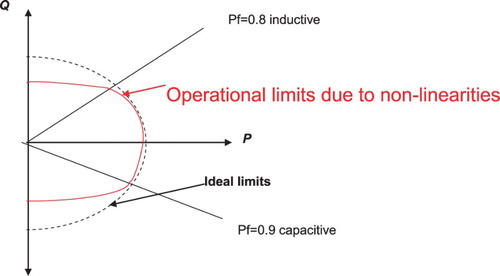
Synchronous generators have the capability to absorb or supply reactive power to the system and the nearby loads. This is done by controlling and adjusting the EMF of the generators via their automatic voltage regulators (AVRs). However, as generators also produce active power demands, their capacity is subject to certain limitations, expressed in terms of apparent, active and reactive power (Prousalidis Citation2011). The permissible operation locus on the P-Q plane is a semicircular one, which is further confined due to design constraints and non-linearities of the generator ().
Figure 3. Operation limitations of generators.
The generator capacity in power is limited in terms of both active and reactive power, which has to be taken into account during the electric load analysis, as explicitly stated in Prousalidis (Citation2011). To this end, in Prousalidis (Citation2011) it is argued that the electric load analysis must be extended to also include the balance of reactive and apparent power demands ().
Figure 4. Extended electric load analysis, including P-balance, Q-balance and S-balance.
Thus, for instance, in , two generators, G1 and G2, of rated power (PN1, QN1) and (PN2, QN2), respectively, are studied versus the power demands obtained from an electric balance with four operating modes. As can be seen, although all active power demands are met by both generators, the reactive power demands are covered only by generator G2, which proves the significance of performing the extended electric balance. In such a case, ‘reactive power compensation' must be put into effect.
Figure 5. Selecting the appropriate generator out of G1 and G2, in order to meet the active and reactive power demands of electric balance analysis (denoted as *).
3.3. Reactive power compensation
The benefits realized by installing reactive power compensation devices include the reduction of reactive power flow on the system, thus increasing line loadability. Therefore, for best results, reactive power compensation should be located as close to the load as possible. However, other reasons may affect the placement of reactive power compensation devices, such as the interaction of harmonics with the device.
In general, most loads that are connected to a power system consume reactive power in addition to active power. The typical reactive power requirements of various components of electrical power systems are presented in .
Table 1. Reactive power demands of certain electrical energy system components.
Some of the reasons to apply reactive power compensation devices are as follows:
Reduction of demands in total electrical energy and hence in the corresponding fuel consumption.
Reduction of I2R losses and therefore heating in the power distribution system.
Increase of the voltage at the load, increasing production and/or efficiency of operation.
Reduction of the current in the distribution lines and transformers, allowing additional load to be served without building new circuits.
Next, a brief overview of alternative reactive power compensation devices is presented, highlighting their various advantages and disadvantages.
4. Alternative components of reactive power compensation
4.1. Synchronous condensers
A synchronous machine with no mechanical load coupled in its shaft is connected in parallel to the electrical energy system and injects reactive power into it. In a manner similar to synchronous generators, the reactive power output of these condensers can be adjusted via their exciters (the DC current of its field winding on the rotor) and, in particular, their associated AVRs. Thus, the condenser can act either as a capacitor (producing reactive power) or as an inductor (absorbing reactive power). This method has been used for quite a long time in shipboard installations with shaft generator schemes (Prousalidis et al. Citation2005).
4.2. Static capacitors
The primary motivation for installing static capacitors is generally to eliminate utility power factor penalties, but there are also technical benefits related to power quality as well. The advantages and disadvantages are as follows:
They are cheaper compared to other solutions.
They have lower losses.
They are less flexible in adjusting their output reactive power.
They can only change the supplied reactive power in steps.
They cannot act as inductors.
During a voltage dip their reactive power produced tends to decrease.
They cannot be overloaded even for short intervals.
They have switching transients during on/off operations.
They need to be located very close to where the problem is.
They have to be connected before the lack of reactive power takes place, otherwise they contribute to the voltage collapse.
During short circuit faults they do not contribute to the system stability.
They are subject to overheating and resonance problems in case of harmonic distortions in the system.
Care should be taken when adding capacitors as they can provoke power quality problems, the most common of which is harmonic distortion. While power factor correction capacitors are not harmonic sources, they can interact with the system to accentuate the harmonics that are already there. There are also switching transient side effects such as the magnification of utility capacitor-switching transients. Furthermore, since the reactive power supplied by the capacitor is proportional to the square of the voltage, for voltage control the capacitor banks should be switched on before they are needed, for maximizing the produced reactive power.
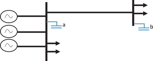
Unlike inland grids, where there are a number of alternative locations for the capacitors, in the ship grid case, considering the compact nature of the power distribution circuit (the distribution network is not too long, the generators are nearby the loads), capacitors can be installed near to large induction motors (location a in ). In the case of long power distribution cabling, an alternative would be to place the compensation capacitor at the local feeding bus supplying a group of motors (location b in ).
Figure 6. Schematic diagram of the potential locations of capacitors.
The optimal design and location for capacitor compensation is often a compromise between conflicting objectives, thus it is difficult to provide clear rules for the location of capacitors. However, general guidelines are as follows:
Capacitors should be located as close to the load as possible, so that losses are minimized and voltage increase is maximized.
A minimum amount of reactive power compensation can be achieved with permanently connected capacitors. In this way connection-disconnection switches are not needed, thus reducing the cost.
Capacitor banks should be used so that the voltage is better controlled in stages.
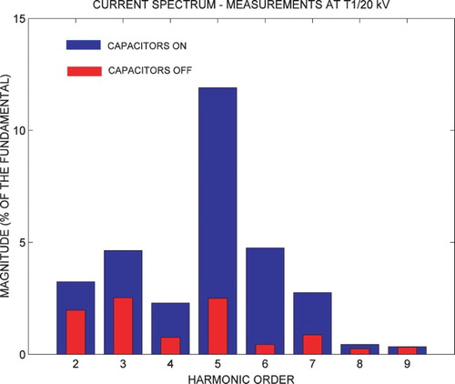
Attention should be paid to avoid any resonance effects due to the presence of the capacitors. For instance, in it can be seen that the harmonic distortion is augmented due to their presence (inland case study at a 20 kV substation).
Figure 7. Harmonic spectrum of current with and without capacitor banks (case study from a power substation on the Hellenic Grid).
Furthermore, during switching on and off, some transients are expected to take place. More specifically:
During the switching on of a capacitor bank, a high-frequency transient inrush current circulates. This current can provoke tripping of the protection breakers.
During the switching off of a capacitor bank, a transient overvoltage is developed stressing the insulation (). Extreme cases of the so-called ‘voltage escalation' can be developed if the protection devices can react and switch off the circuit with the capacitors very fast (Papadias Citation1985; Greenwood Citation1991).
Figure 8. Transient overvoltage during the switching off of a capacitor bank (case study from a power substation on the Hellenic Grid).
4.3. Static VAr compensator
The static VAr compensator (SVC) is a more sophisticated reactive power source comprising a capacitor bank, the connection of which is controlled by a power electronic switch (e.g. a thyristor). The SVC can be considered as the component that combines the advantages of a synchronous condenser (accurate control of the output reactive power without adverse transients) and a capacitor bank (without any rotating parts). This device is fairly costly as it is fast reacting, has an increased number of steps of reactive power, and possesses the capacity to absorb reactive power as well as provide it. It is worth noting that as power electronic devices are sensitive to temperature, the installation of such a device onboard a ship requires a very thorough study of the ambient operating conditions.
5. Establishing a methodology to assess the feasibility of installing a reactive power source
In this section a methodology is established to assess the feasibility of installing a reactive power source. Thus, the circuit is considered both before and after the installation of the source and the operating conditions are compared. The resultant difference yields to difference in circulating active losses (in W) which can be transformed into fuel and emissions.
5.1. Before the installation of any reactive power compensation source
When no reactive power source is present, see , power equilibrium is described by equations (7)–(12)
(5)
(6)
(7)
(8)
(9)
(10)
(11)
(12)
5.2. After the installation of any reactive power compensation source
In this case, where a reactive power source is installed, see , the total reactive power demands are:
(13) while the power factor at the main bus becomes
(14)
Assuming that the bus voltage remains the same, i.e., equal to V, the current is
(15)
The total losses in this case are obtained from
(16)
Hence, the resultant energy savings are obtained from
(17)
This ΔP directly reflects the fuel savings at the generator sets and can be transformed into greenhouse gas reduction too.Footnote1
The energy savings (as well as the corresponding fuel savings and emission reduction) have to be taken into account in the calculation of the net present value (NPV) of the retrofitting reactive power source. In the NPV calculation, the following costs must be also taken into account:
Procurement and installation costs.
Operational costs.
Maintenance costs.
5.3. Factors that must be considered
Reactive power compensation is not an ultimate solution for energy saving, but it can be used in certain cases provided a careful and thorough study has been performed beforehand. In general, it can be argued that considering that the loads (both static and dynamic) are nearby the synchronous generators, which are reactive power sources, it is not by default necessary to install another reactive power source.
Furthermore, there are a number of other factors relating to the selection of the optimum reactive power compensation method, and these are as follows:
The ambient conditions (temperature and humidity) must be carefully examined. For instance, an SVC based on power electronic devices installed within the engineering room can result in even bigger problems.
The synchronous condenser is expensive, heavy, large in volume and incurs significant maintenance costs; but as a method for reactive power compensation it is robust and can react quickly to maintain a constant voltage at the terminals. It can also be further exploited for short circuit studies and the stability of the network.
Capacitor banks provoke transient inrush currents during energization and transient overvoltages during de-energization. Furthermore, they can boost the already present harmonic distortion of both current and voltage waveforms. It is worth noting that the order of magnitude of their reactive power should be between 15% and 25% of the apparent operating power of the equipment to be compensated, otherwise the impact of their presence can be negative. Moreover, during energization they should not have any stored charge as this might increase the adverse switching phenomena.
The AVRs of the generators are often used during synchronization as well as for voltage stabilization and proper reactive load sharing among the generators. Among all the equipment for regulating the reactive power flow, this is the least heavy and volume demanding. It has to be noted, though, that it is subject to frequent failures, while users are not accustomed to regulating reactive power via proper settings in the AVRs.
The methodology, as outlined above, before deciding on the level and method of reactive power compensation should include the following:
Verification of the electric load analysis so that the energy demands of the ship electrical energy system are confirmed. To this end, related measurements, reports of problems, etc. should be taken into account too. Interest is mainly focused on large power equipment.
Estimation of the power factor.
Estimation of the installation costs of the alternative reactive power sources.
Estimation of the maintenance costs of alternative reactive power sources.
Estimation of the energy savings via simulations and/or calculations.
Estimation of the environmental impact of the reactive power source under study. To this end, the energy savings and emission reduction during ship operation due to this source must be considered, but this must also take into account the energy demands for its production in terms of modern life cycle analyses.
6. Case studies
6.1. Electric load analysis including reactive power demands
6.1.1. A small passenger ferry case study
Following the methodology described above for the detailed design of the electrical energy system of a small passenger ferry utilizing either conventional propulsion or diesel electric propulsion (Sofras & Prousalidis Citation2014), the extended reactive load analysis and the calculation of the power factor (pf) of the electric grid have been elaborated and the results are presented in Tables and .
Table 2. Reactive power analysis and pf (power factor) calculations for conventional propulsion.
Table 3. Reactive power analysis and pf calculations for diesel electric propulsion.
It can be seen that the power factor is in the order of 0.85 inductive, so no course of action is required for that case.
6.1.2. Analysing the generator reactive overloading of an LPG carrier
This case study refers to the electric energy system of an actual liquefied petroleum gas (LPG) carrier, focusing in particular on one of the main loads of the electric grid comprising two low-speed asynchronous motors driving compressors. The rated power factor of these motors is 0.6 (inductive), while in ‘sailing-at-sea' mode the generators have been proven to operate with a total power factor in the order of 0.45. The rest of the loads have standard behaviour with a mean 0.8 power factor (always of the inductive type). The active power demands are well below the nominal power of the generators, yet the generators were still overloaded in terms of reactive power by 13.9% (). By performing a thorough study (comprising calculations, simulations and measurements), the power factor of the compressor motors was proven to be equal to the extremely small value of 0.24 (Prousalidis Citation2011). Due to the high reactive power demands, this overloading condition in steady-state operation could lead to instability in the generators, as can be deduced by inspecting the voltage vs reactive power curve ().
Figure 9. Feeding bus supplying M loads (k = 1, 2, … , M) without any reactive power source.
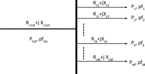
Figure 10. Feeding bus supplying M loads (k = 1, 2, … , M) with a reactive power source installed.
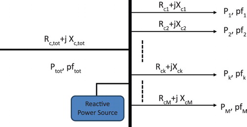
Figure 11. Voltage vs. reactive power curve of synchronous generators. (If the generator is forced to cover excessive reactive power demand, this could to the unstable region.) (Papadias Citation1985, Prousalidis Citation2005).
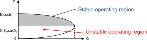
Figure 12. Simulation setup in the CitationMATLAB environment.
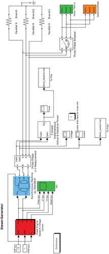
Figure 13. Energy demands in terms of active and reactive power from the system vs. reactive power capacitor.
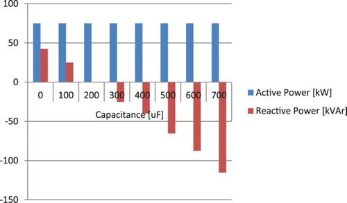
Table 4. Reactive power overloading of the generators due to low power factor motors of an LPG carrier in actual operating conditions.
Unlike the small passenger ferry case study, some measures had to be taken. The problem was finally resolved by installing reactive power compensating capacitors at the motor connection bus-bar. In this way, the capacitors provided the extra reactive power that the generators could not supply. However, this retrofitting could have been avoided if an extended electric load analysis had been carried out at the design stage which included the equilibrium of reactive power.
6.2. Investigating the impact of capacitance
In this simplified case study, a generator supplies the energy for an induction motor of 75 kW rated power and with an inductive power factor of 0.85. A capacitor unit is connected in parallel with the motor in order to help it start up and reduce the energy demands (especially in terms of reactive power) from the generator. The investigation was performed in a CitationMATLAB environment ().
On this occasion, the impact of the capacitance value upon the active and reactive power demands was investigated. The value of the capacitor varied from 100 µF up to 700 µF, which corresponds to a reactive power variance between 15% and 85% of the rated apparent power of the motor ().
Based on the results as shown in the figures, the following conclusions were drawn:
It was confirmed that the capacitance has a significant impact on the reactive power demands. Thus, the reactive power Q is improved in the cases of 100 µF, 200 µF and 300 µF corresponding to reactive power of 15% up to 45% of the rated apparent power of the compensated load. However, there is a threshold value of the capacitance beyond which the reactive energy demands are reversed. This confirms the ‘rule of thumb’ for installing capacitors that their reactive power must be in the order of one third of the motor rated capacity.
On the other hand, there is zero impact on the active power demands, as the active power P shows no remarkable change. This verifies that the rule |I|2RdistributionLines cannot be that significant considering the small lengths of distribution cabling.
Moreover, in order to make the analysis as thorough as possible, the environmental impact of the capacitors used was estimated. Thus, the specific fuel oil consumption in three different scenarios was calculated, namely without any capacitor and when the capacitance value is equal to 100 µF and 200 µF (). Moreover, in the cases where a capacitor is installed, the impact of its manufacturing process has also been included (CitationCPM LCA Database; CitationTiina Alaviitala). More specifically, the CO2 emission factor for capacitor construction is estimated as 3.57 g of CO2 per capacitor weight in g (CitationCPM LCA Database; CitationTiina Alaviitala), while the diesel fuel emission factor is considered approximately equal to 3 kg of CO2 per fuel mass in kg.
Table 5. CO2 emission calculations for a 75KW electric motor.
Taking into account that the latter is a rather small value, it seems that the installation of a capacitor bank is beneficial.
7. Conclusions
In this paper, the main principles of reactive power compensation onboard ship electrical energy systems are discussed. It is shown that if the generators cannot meet the reactive power demands of the loads, alternative compensation methods can be used via retrofitting procedures. This can lead to a reduction of active power losses, which in turns leads to a reduction in fuel consumption and emissions. It is further concluded that static capacitors are one of the most feasible solutions to this problem.
Acknowledgments
The work presented in this paper has been developed within the framework of the Thales-Defkalion Project.
Disclosure statement
No potential conflict of interest was reported by the authors.
Funding
This work was supported by the European Union European Social Fund (ESF) and Greek national funds through the ‘Education and Lifelong Learning’ Operational Programme of the National Strategic Reference Framework (NSRF) Research Funding Programme: THALES: Reinforcement of the Interdisciplinary and/or Inter-institutional Research and Innovation [grant number MIS: 380164].
Notes
1. For instance, if the fuel is diesel fuel oil, the emissions are 0.69 tCO2/MWh, 0.0139 tNOx/MWh, 0.0011 tSOx/MWh, 0.0004 tHC/MWh, and 0.0003 tPM/MWh, while in the case of heavy fuel oil, the emissions are 0.722 tCO2/MWh, 0.0147 tNOx/MWh, 0.0123 tSOx/MWh, 0.0004 tHC/MWh, and 0.0008 tPM/MWh.
References
- CPM LCA Database – Capacitor for Surface mounting Ericsson RJC 388, RJC 441 Capacitor Size 1206.
- Greenwood A. 1991. Fast Electromagnetic Transients. New York, NY: John Wiley and Sons.
- Papadias BC. 1985. Analysis of electric energy systems-Part II: transient state operation. Athens: Papadamis Publications.
- Prousalidis J. 2011. The necessity of reactive power balance in ship electric energy systems. IMarEST Journal of Marine Engineering and Technology. 10(January):37–47.
- Prousalidis J, Hatzilau IK, Michalopoulos P, Pavlou I, Muthumuni D. 2005. Studying ship electric energy systems with shaft generator. Proceedings of International Symposium on Electric Ship Technologies (ESTS05), Philadelphia – USA (25–27 July).
- Prousalidis J, Kourtesis C. 2014. Ship electric energy systems: design and operation principles. London: IMarEST Publications, ISBN:978–0–9565600–4–9.
- Sofras E, Prousalidis J. 2014. Developing a new methodology for evaluating diesel-electric propulsion. Proceedings of the Institute of Marine Engineering, Science and Technology, Journal of Marine Engineering and Technology 13(3) December:63–92.
- The Mathworks Inc, MATLAB User Manual.
- Tiina Alaviitala – Life cycle assessment of power capacitors Master's Thesis – Tampere University of Technology – Faculty of Computing and Electrical Engineering.