
 ?Mathematical formulae have been encoded as MathML and are displayed in this HTML version using MathJax in order to improve their display. Uncheck the box to turn MathJax off. This feature requires Javascript. Click on a formula to zoom.
ABSTRACT
This paper proposed an inverter control scheme for wind energy system under weak grid conditions. Wind-based hybrid energy system (HES) is often having the issue of poor transients and slow dynamic response due to the unpredictable nature of the wind speed and inertia of the generator who cannot respond the changes instantly. The proposed control scheme is designed to improve the transients and dynamic responses of the wind energy system. The control scheme introduces super-capacitor (SC) fast charging/discharging characteristics in the inverter control using a bidirectional buck–boost converter to improve the transients and the frequency response of the system. The inverter control scheme under the weak grid conditions is designed and analysed. The proposed control can be applied in the marine electrical system where wind system is installed in the marine to reduce fuel consumption and improve electric power quality. Wind-based HES is modelled and simulated in the MATLAB to demonstrate the effectiveness of the proposed control scheme under different conditions. The results are presented and compared to the conventional control scheme to justify the improvement in the power quality and the frequency response of the system.
Nomenclature
| HES | = | hybrid energy system |
| SC | = | super-capacitor |
| DFIG | = | doubly fed induction generator |
| PMSG | = | permanent magnet synchronous generator |
| PCC | = | point of common coupling |
| Udc | = | DC link voltage |
| Cdc | = | DC link capacitance |
| LCL | = | inductance–capacitance–-inductance |
| L1, L2 | = | filter inductance |
| Cf | = | filter capacitance |
| Usabc | = | three-phase grid voltage |
| Ugabc | = | three-phase voltage at PCC |
| Rg, Lg | = | grid resistance and inductance |
| dsw3, dsw4 | = | duty cycles of buck boost converter |
| isc, vsc | = | SC current and voltage |
| i*gd, i*gq | = | reference d and q-axis grid current |
| igd, igq | = | d and q-axis grid current |
| Ugd, Ugq | = | d and q-axis grid voltage |
| Usd, Usq | = | d and q-axis voltage at PCC |
| Pg | = | power injected into the grid |
| Pinv | = | input power of the inverter |
| iinv | = | inverter input current |
| idc | = | DC link capacitor current |
| Ud, Uq | = | d and q-axis inverter output voltages |
| ω | = | angular frequency |
| = | d and q-axis ripple currents | |
| U*d, U*q | = | d and q-axis reference inverter voltages |
| fs | = | switching frequency |
| Gc(s) | = | gain of the outer current control loop |
| Kp | = | gain of the inner current control loop |
| Kpwm | = | gain of the inverter |
| Gv(s) | = | gain of PI voltage controller |
| Gcl_i(s) | = | transfer function of the grid current closed-loop control |
| Gol_v(s) | = | transfer function of the open-loop voltage control |
| P.M., G.M. | = | phase margin and gain margin |
| Pcomp | = | compensated power |
| i*sc | = | reference SC current |
| Gpi_sc(s) | = | gain of PI regulator of the SC control loop |
| Gid_sc(s) | = | gain of bidirectional dc/dc buck–boost converter |
| Gcl_sc(s) | = | closed-loop transfer function of SC current control |
| Gol_v(s) | = | open-loop transfer function of the proposed voltage control loop |
1. Introduction
In today's scenario, energy shortage is the rising problem in front of the world globally because of sharp consumption of fossil fuel, increase in energy consumption and to maintain environment pollution free (Nehrir et al. Citation2012). Therefore, research on renewable energy-based marine electric power systems is getting more attention on every passing day. In the renewable energy systems, wind energy system is the most viable option today because of low-to-medium power-generation capability, more reliable, availability near coastal areas and cheaper cost as compared to other options (Yaramasu et al. Citation2015). But, wind-based hybrid energy systems (HESs) have many challenges due to the unpredictable nature of the wind, the slow response of the generator under transient conditions and the sensitivity of the marine power system stability (Orlando et al. Citation2013). Moreover, wind-based HES may affect the other loads also in the marine system and pollute the power quality. The marine electric system behaves as a weak grid system having low voltage, high impedance network (low-to-medium power). Therefore, control must be designed after considering the line impedance to improve the stability, frequency and short circuit current response.
In the recent literature, some control designs are proposed for wind-based energy systems connected to weak grid or the microgrid may be utilized in the marine electric system. In Fatu et al. (Citation2014), the authors have proposed the dual inverter-based control of harmonic suppression and transition control from the grid to stand alone or vice versa. The authors in Zeni et al. (Citation2016) proposed power oscillation damping control of offshore wind system using damping control. Steady-state oscillations are effectively damped out by the proposed control, but the stability margin is not improved. In Van de Vyver et al. (Citation2016), droop-based synthetic inertial control is proposed for participation in frequency support under sudden changes, but the inertial response is highly dependent on fixed system parameters (highly unlikely in microgrid) to tune properly, otherwise, it may deteriorate the frequency response and introduces power oscillations. Transient stability enhancement using adaptive neuro fuzzy control for grid-connected wind farm is discussed in Erratum (Citation2015) using flywheel storage, but the power oscillations and dynamic response of the wind system connected to the weak grid. In Lumbreras et al. (Citation2016), control of small wind turbine under the high wind speed is proposed in grid-connected mode to improve the system response. In Kollimalla et al. (Citation2014), Gee et al. (Citation2013), the author has proposed SC and battery control to improve the transient and dynamic response of the wind energy system. Similarly, in Baronti et al. (Citation2013) the authors have proposed super-capacitor (SC) and battery control for the DC microgrid to improve the slow dynamic response of the battery in the HESs. The authors in Tan et al. (Citation2016) discussed the control method of a wind system in microgrid which effectively enhanced the transient response of the system. In Hossain and Ali (Citation2016), a transient stability control method using DC resistance is introduced to limit the fault current but this method has limited application and restricted to fault conditions. Wind-based HES connected to the grid is discussed in Mangu et al. (Citation2016), this method is effective to improve the efficiency and reliability of the low-power system. In Hu et al. (Citation2016), the paper has concluded the analysis of the stability problems associated with microgrid. The authors of Naidu and Singh (Citation2017) have proposed the effective control method to enhance the transient stability of the doubly fed induction generator (DFIG)-based wind system using batteries. In Peña-Alzola et al. (Citation2017), the authors improved the current and torque quality of the permanent magnet synchronous generator (PMSG) generator by blocking ripples from the DC link voltage into the PMSG armature current. The high-frequency resonance problem associated with wind system connected to weak network is discussed in Song et al. (Citation2017). The virtual resistance control has improved the performance, but the variation of virtual resistance is limited and restricted the damping of the resonant frequency.
The proposed scheme for inverter control of the wind-based HES is designed in this paper. The wind system consists of PMSG-based wind turbine, energy storage devices such as SC, bidirectional buck–boost converter and inverter. In this paper, the proposed control scheme is designed to achieve:
Improved transient response under a sudden change in operating conditions.
Fast dynamic response of the DC link voltage regulation.
Improved frequency response of the power injected into the microgrid.
The paper has been categorized into four sections. Section 2 includes the analysis of the conventional design and mathematical design of the proposed control scheme. In Section 3, results are presented and discussed the comparative analysis of the conventional and the proposed control scheme. Finally, Section 4 concludes the findings of the study of the wind-based HES.
2. Description of the system structure
This paper proposes a novel control scheme to address the problems of HES, connected to the weak grid, in different operating conditions. HES has the capability to provide power in grid-connected as well as standalone conditions for better utilization. The energy storage devices in HES are used to maintain DC link voltage constant under standalone/islanding mode only whereas, energy storage devices kept standby in HES under grid-connected mode. Unlike the conventional control, in this paper, SC, as an energy storage device, is used to participate in the inverter control of the wind system connected to the weak grid also. This control scheme is not inducing any increase in cost. However, the proposed control scheme only utilizes the availability of the energy storage devices of the HES to improve the stability and power quality.
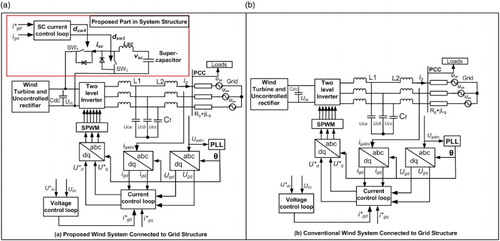
Figure (a) and (b) shows the detailed structure of the wind-based energy system with the proposed and the conventional control scheme, respectively. The wind turbine-generator set is connected to the DC link voltage Udc through an uncontrolled rectifier across a DC link capacitance Cdc. DC link is connected to the controlled inverter to inject AC power into the weak grid. Inverter and the grid are connected with the help of an inductance–capacitance–-inductance (LCL) filter to suppress harmonics. LCL filter parameters are chosen according to the ratings of the system using the literature Reznik et al. (Citation2014), where the detailed designing of the filter is reported. LCL filter having inductance L1, L2 and capacitance of Cf, where igabc is the three-phase current injected into the grid, Usabc is the three-phase grid voltage, Ugabc is the three-phase voltage at PCC, Rg+jLg is the grid impedance. In the proposed structure, extra circuit is proposed to improve the performance of the wind energy system which consists of SC and bidirectional buck–boost converter, where SW3 and SW4 are the IGBT switches of the converter, dsw3 and dsw4 are the duty cycle of the switches to control the charging/discharging of the SC, isc is the SC current and vsc is the voltage of the SC. To design the control schemes of the system, variables are transformed from the stationary (abc) to synchronous (dq0) reference frame using abc/dq0 transformation Leva and Morando (Citation2006). In the synchronous reference frame, i*gd and i*gq are the reference grid current of the d and q-axis respectively, igd and igq are the grid current of the d and q-axis respectively. Similarly, Ugd and Ugq are the d and q-axis voltages at PCC, Usd and Usq are the d and q-axis of the grid voltages. The wind energy system is connected to the weak grid to analyse the behaviour of the offshore wind parks, small non-interconnected systems, microgrid systems, etc. The weak grid is defined as the grid having a low voltage level (short circuit current level is less than 2 MVA), Xg/Rg <3 and grid impedance has to be considered into account for a valid conclusion.
Figure 1. Structural diagram of grid-connected (a) proposed wind system (b) conventional wind system.
2.1. Analysis of the conventional control scheme
In this section, the conventional control scheme is mathematically analysed as shown in Figure . The conventional control scheme has two stages to control DC link voltage and reactive power control. The voltage control loop is used to maintain DC link voltage constant irrespective of the change in the operating condition. The current control loop is used to regulate the d-axis and q-axis current. The reference of d-axis current is obtained through the voltage control loop to maintain DC link voltage constant and to control the active power injection into the grid through the d-axis current regulation. The reference of q-axis current is set at zero to maintain unity power factor through reactive power control using q-axis current regulation.
Figure 2. Structure of the conventional control scheme.
Now, the power balancing equation for grid-connected wind energy system can be written as:
(1)
(1)
where Pg is the power injected into the grid and igq is set at zero.
The input power of the wind system is available as DC power at the DC link of the inverter can be written as:
(2)
(2)
where Pinv is the input power of the inverter, iinv is the inverter input current and idc is the DC link capacitor current and can be written as:
(3)
(3)
If Udc is maintained constant, then idc is zero. Therefore, idc is the transient current and will be absent under steady-state condition.
Therefore, the input power of the inverter is
(4)
(4)
Now, according to the power balancing condition, input power should be equal to output power and can be expressed as
(5)
(5)
Therefore, the voltage control loop can be designed as per Equation (5), where can be seen clearly the output of the voltage controller is i*gd to maintain DC link voltage constant.
Similarly, the equations of the inverter output voltages Ud and Uq can be written as:
(6)
(6)
(7)
(7)
where,
and ω is the angular frequency.
With the help of the feed-forward decoupled control, the output of the current controller is added to get reference voltages as
(8)
(8)
(9)
(9)
With the help of Equations (8) and (9), the current control loop can be designed to regulate d and q-axis current to control active power and reactive power, respectively.
But, in the weak grid, the conventional control having problems of slow dynamic response, steady-state ripples and reduced stability margin can be mathematically analysed as given below:
Under transient conditions, DC link voltage is fluctuated, which change the reference grid current needed to maintain the DC link voltage constant, therefore, any change in operating conditions is directly reflected into reference currents as
(10)
(10)
(11)
(11)
where,
and
are the values of current (can be negative also) that get added up in the previous grid current values under transient conditions into the reference currents. But, changes in reference current do not get directly reflected in the feed-forward decoupled control components
and
, because both components are directly dependent on the actual current only and the controller will take some time to track the reference current. Therefore, as a result, the dynamic response of the grid current control loop is slow.
Steady-state ripples also remain present in the grid current as non-linear loads inject lower order harmonics at steady state, to suppress the harmonics with the conventional control scheme is not possible. Therefore, grid current at steady state can be written as:
(12)
(12)
(13)
(13)
where,
and
are the ripple currents under steady-state condition. These ripples affected the quality of the grid current and affect the coupling terms also. Now, reference voltages at steady state can be written as:
(14)
(14)
(15)
(15)
As the desired d and q-axis voltages contain the terms
and
as per (14) and (15), this will interact and further worsen the quality of the grid current.
Voltage controller stability is the main concern in the weak grid conditions, where the grid impedance is an unknown variable over a wide range and depends on operating conditions. Therefore, Stability of the conventional control scheme is analysed by considering voltage control loop bandwidth less as compared to the inner current control loop bandwidth because the voltage PI controller is tuned based on the inner current control loop. Figure shows the mathematical model of inverter control connected to the weak grid, consists of the inner loop proportional regulator and the PI regulator. Switching frequency fs of the inverter is taken as 10 kHz, where Gc(s) is the gain of the outer loop PI regulator, Kp is the gain of the proportional regulator and Kpwm is the gain of the inverter. According to Figure , the closed-loop transfer function is
(16)
(16)
where,
,
and
Figure 3. Mathematical model of weak grid-connected inverter control.
The open-loop transfer function of voltage control loop can be derived as per Figure , where, Gv(s) is the gain of PI voltage controller, Gcl_i(s) is the grid current closed-loop control gain.
Now, voltage control loop has three controller gains; Gv(s), Gc(s) and Kp where Gv(s) and Gc(s) can be written as:
(17)
(17)
(18)
(18)
Therefore, open-loop transfer function Gol_v(s) of the voltage control loop can be written as
(19)
(19)
The controllers are designed to achieve high bandwidth and good stability margin. The values of controller gains so obtained are as follows: Kp=10.6, Kp_c=7.2, Ki_c=12,000, Kp_v= 0.221, Ki_v=110.36, where Kpwm is assumed as unity. Now, phase margin (P.M.) and gain margin (G.M.) are 103 degrees and 15 dB, respectively obtained in MATLAB from the open-loop bode plot of Gol_v(s), when the value of grid inductance Lg=0. The cut-off frequency is around 2 kHz (approximately fs/5).
Now, the impact of the grid impedance on the stability of the voltage control loop at the conventional scheme is analysed. The impact of the grid resistance is negligible (even resistance has improved the stability of the control very slightly) in the control scheme (Chen et al. Citation2016). Therefore, assuming rg=0, the effect of Lg is studied. The open-loop bode plots are shown in Figure with different values of grid inductance Lg for voltage control loop.
Figure 4. Bode plots of the voltage control loop.
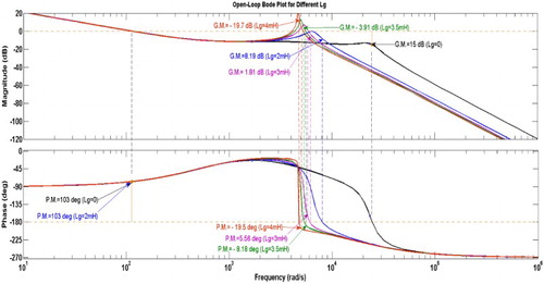
When Lg=2 mH, phase and gain margins are 103 degrees and 8.19 dB, respectively, which provides reasonably good stability margins, but the margins get reduced as compared to the case when the value of Lg was considered as zero. Similarly, at Lg=3 mH, the voltage control loop stability margins decrease sharply as P.M. and G.M. are 5.56 degrees and 1.81 dB, respectively. Also, the voltage control loop becomes unstable when Lg=3.5 mH, 4 mH or more where, both phase and gain margins are negative as shown in Figure . Under a weak grid condition, stability analysis shows that the conventional control scheme does not provide good stability margins and robustness of the voltage control loop. Not only this, even system instability arises under the large values of grid inductance.
2.2. Design of the proposed control scheme
The proposed control scheme is designed to overcome the problems associated with the conventional control scheme. Therefore, SC control is utilized to improve the dynamics of the overall control scheme. The mathematical analysis of the conventional control scheme has proven that is the responsible factor of slow dynamic response. In the proposed control scheme,
is regulated by the SC with bidirectional buck–boost converter control using SC fast charging/discharging characteristics.
The proposed control is designed using the mathematical equations as follows:
Under steady-state condition, the power equation can be written as
(20)
(20)
Now, under transient conditions, the equation can be
(21)
(21)
In Equation (21), Equation (10) can be replaced and rewritten as
(22)
(22)
Therefore, with the help of Equations (20) and (22), we get
(23)
(23)
Now, this can be compensated by SC control in transient condition only, if
is positive, then bidirectional dc–dc converter works on boost mode (discharging) from vsc(low voltage) to Udc(high voltage), otherwise in buck mode (charging) from high voltage to low voltage.
Now, to regulate this current, the power is needed to compensate using SC charging/discharging, therefore the equation can be written as
(24)
(24)
where the Pcomp is power to be compensated by SC.
Therefore, SC is needed to supply/absorb the same amount of power, Equation (24) can be rewritten as
(25)
(25)
Therefore, the reference SC current can be written as
(26)
(26)
Therefore, with the help of Equation (26), the proposed control scheme is designed as shown in Figure . Under transient conditions when is not zero, i*sc is also present and SC control is utilized to compensate for the transients. Under steady-state condition when
is zero, i*sc is also absent and SC will not participate in a steady-state condition.
Figure 5. Structure of the proposed control scheme.
In the proposed control scheme, the voltage and the grid current control loops are designed and their stabilities are analysed. SC current control loop is faster than the grid current control loop, therefore, the voltage control loop is tuned based on SC current control loop. Figure shows the SC current control loop where Gpi_sc(s) is the gain of the PI regulator and Gid_sc(s) is the gain of bidirectional dc/dc buck–boost converter (Jin et al. Citation2009).
Therefore, Gpi_sc(s) and Gid_sc(s) can be written as:
(27)
(27)
(28)
(28)
Now, closed-loop transfer function of SC current control Gcl_sc(s) can be written as,
(29)
(29)
Figure shows the voltage control loop, based on SC current control loop, comprising Gv(s) as PI regulator gain, Gcl_sc(s) as the transfer function of closed-loop SC control loop and Gv_dc(s) as the transfer function (Leva and Morando Citation2006) of SC inductor current to DC link voltage.
Figure 6. Block diagram of voltage controller with the proposed control scheme.
Therefore, Gv(s) and Gv_dc(s) can be written as:
(30)
(30)
(31)
(31)
From Equations (29), (30) and (31), the open-loop transfer function of the voltage control loop, Gol_v(s) can be written as:
(32)
(32)
Hence, Equation (32) shows that the transfer function of the voltage control loop is totally independent of Lg. Controllers are designed for high bandwidth and good stability margins by using the diagram-aided method. The details of controller gains obtained are as follows: Kp=10.6, Kp_c=4.09, Ki_c=6193, Kp_sc= 0.005, Ki_sc=5, Kp_v=0.077, Ki_v=77, where Kpwm is assumed as unity.
Open-loop bode plot of the control loop with different values of Lg is shown in Figure . Large variations in grid inductance are taken from Lg=0 to 6 mH to analyse the stability of the grid current control loop. In the proposed control scheme, the range of system stability in terms of variations in grid inductance is increased significantly (Lg=0–6 mH), whereas, in the conventional control, this was limited up to Lg=3 mH only. Although, the grid current control loop in the proposed control scheme is dependent on grid inductance, it provides a much better stability margin even with large values of Lg.
Figure 7. Bode plots with different values of Lg.
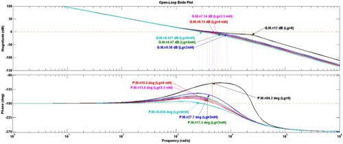
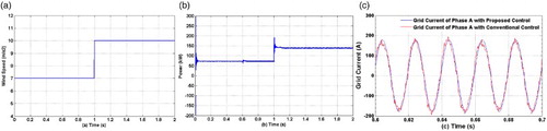
Figure 8. Waveforms of (a) wind speed (b) wind power (c) grid current.
3. Results and discussion
The proposed control strategy has been implemented on a 150 kW wind-based HES under weak grid conditions. To justify the improved performance of the proposed control strategy, the system is simulated in MATLAB under different operating conditions. The parameters of the system are used in the simulation, given in Tables and .
Table 1. Storage device parameters.
Table 2. Nominal system parameters.
Figure (a) shows the waveform of wind speed given to the wind turbine, where a change in wind speed is introduced at 1 s to demonstrate the dynamic and transient behaviour of the proposed control scheme as compared to the conventional scheme. In Figure (b), power output of the wind energy system is shown corresponding to the wind speed. As clearly seen, in Figure (c) that the grid current of the wind energy system with the proposed control is much better steady-state response as compared to the conventional control. Ripples are suppressed in the proposed scheme, whereas in the conventional control, significant ripples are present in the grid current. Therefore, the proposed control scheme is providing improved power quality as compared to the conventional one
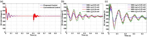
Figure (a) shows the waveform of DC link voltage with proposed control and the conventional control in which the DC link voltage shows much improved transient stability and fast dynamic response as compared to the conventional control under different operating conditions. Figure (b) and (c) shows the behaviour of the DC link voltage with different grid impedances, where the waveforms are lower oscillations and transients with the proposed control scheme even in high grid inductance, but the waveforms of DC link voltage are having adverse transients and oscillations with the conventional control scheme under weak grid conditions.
Figure 9. Waveforms of DC link voltage (a) under transient conditions (b) under different Lg with the proposed scheme and (c) under different Lg with the proposed scheme.
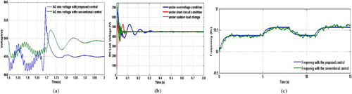
In Figure (a), the grid voltage of the system is maintained throughout constant irrespective of change in wind speed/load with better transients which shows the effectiveness of the proposed control scheme. Similarly, Figure (b) shows the behaviour of the grid current, under a change in wind speed as well as the power output of the wind turbine, the grid current is increased to control the injected power into the grid with improved transients and steady-state response. Figure (c) shows the waveform of the phase A grid current and voltage to justify the effective control of the reactive power, where both are in-phase, which shows the unity power factor of the injected power because q-axis current reference is taken as zero. The AC voltage, DC link voltage and frequency response of the wind energy system are shown in Figure . Figure (a) shows the waveform response of the RMS AC voltage under fault conditions. The AC voltage response showed improvement in the waveform under fault condition with the proposed control as compared to the conventional control. Similarly, Figure (b) shows the response of DC link voltage under different conditions, which represents the robustness of the control to maintain regulated DC link voltage. Lastly, the frequency response of the system shown in Figure (c), the frequency response to the proposed control shows better results as compared to the conventional control.
Figure 10. Waveforms of (a) grid voltage (b) grid current and (c) phase A grid current and voltage.
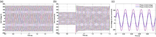
Figure 11. Waveforms of (a) AC voltage under a fault condition, (b) DC link voltage and (c) frequency.
4. Conclusion
A novel proposed control design for wind-based energy system is discussed and tested under different conditions. The results have shown the effectiveness of the proposed control scheme as compared with the conventional control. Power quality is improved with the proposed control scheme as seen in the results. Stability of the controller is improved as compared to the conventional control which is clearly indicated by the DC link voltage waveforms and the bode plot analysis. Also, the results justify the effectiveness of the proposed control scheme to control active power and reactive power with the help of d and q-axis current. DC link voltage transient stability is improved considerably as well as a fast dynamic response is achieved with the proposed control scheme as shown in the results. Therefore, the proposed control scheme has proved effective to improve the overall response and behaviour of the wind-based energy system under different operating conditions as compared to the conventional control scheme. The proposed control scheme is able to provide quality power for sensitive marine loads. Therefore, the proposed control scheme may be utilized in the marine electric power system by integrating wind systems to reduce fossil fuel consumption.
Disclosure statement
No potential conflict of interest was reported by the authors.
References
- Baronti F, Fantechi G, Roncella R and Saletti R. 2013. High-Efficiency digitally controlled charge equalizer for series-connected cells based on switching converter and super-capacitor. IEEE Trans Ind Inform. 9: 1139–1147. doi: 10.1109/TII.2012.2223479
- Chen X, Wang Y, Zhang Y, Chen J, Gong C. 2016. Hybrid damping adaptive control scheme for grid-connected inverters in a weak grid. IET Power Electron. 9:2760–2768. doi: 10.1049/iet-pel.2015.1016
- Erratum. 2015. Transient stability enhancement of a grid connected wind farm using an adaptive neuro fuzzy controlled-flywheel energy storage system. IET Renew Power Gen. 9:864.
- Fatu M, Blaabjerg F, Boldea I. 2014. Grid to standalone transition motion-sensorless dual-inverter control of PMSG With asymmetrical grid voltage sags and harmonics filtering. IEEE Trans Power Electron. 29:3463–3472. doi: 10.1109/TPEL.2013.2279883
- Gee AM, Robinson FVP and Dunn RW. 2013. Analysis of battery lifetime extension in a small-scale wind-energy system using supercapacitors. IEEE Trans Energy Conver. 28: 24–33. doi: 10.1109/TEC.2012.2228195
- Hossain MM, Ali MH. 2016. Transient stability improvement of doubly fed induction generator based variable speed wind generator using DC resistive fault current limiter. IET Renew Power Gen. 10:150–157. doi: 10.1049/iet-rpg.2015.0150
- Hu J, Hu Q, Wang B, Tang H, Chi Y. 2016. Small signal instability of PLL-synchronized type-4 wind turbines connected to high-impedance AC grid during LVRT. IEEE Trans Energy Convers. 31:1676–1687. doi: 10.1109/TEC.2016.2577606
- Jin Y, Xu J, Zhou G, Mi C. 2009 . Small-signal modeling and analysis of improved digital peak current control of boost converter. In: Proceedings of the IEEE 6th International Power Electronics Motion Control Conference; 2009 May 17-20; Wuhan.
- Kollimalla SK, Mishra MK, Narasamma NL. 2014. Design and analysis of novel control strategy for battery and supercapacitor storage system. IEEE Trans Sustain Energy. 5:1137–1147. doi: 10.1109/TSTE.2014.2336896
- Leva S, Morando AP. 2006. Analysis of physically symmetrical lossy three-phase transmission lines in terms of space vectors. IEEE Trans Power Del. 21:873–882. doi: 10.1109/TPWRD.2005.858740
- Lumbreras C, Guerrero JM, García P, Briz F, Reigosa DD. 2016. Control of a small wind turbine in the high wind speed region. IEEE Trans Power Electron. 31:6980–6991. doi: 10.1109/TPEL.2015.2508674
- Mangu B, Akshatha S, Suryanarayana D, Fernandes BG. 2016. Grid-Connected PV-wind-battery-based multi-input transformer-coupled bidirectional DC-DC converter for household applications. IEEE J Emerg Sel Top Power Electron. 4:1086–1095. doi: 10.1109/JESTPE.2016.2544789
- Naidu NKS, Singh B. 2017. Grid-Interfaced DFIG-based variable speed wind energy conversion system With power smoothening. IEEE Trans Sustain Energy. 8:51–58. doi: 10.1109/TSTE.2016.2582520
- Nehrir H, Caisheng W, Strunz K, Aki H, Ramakumar R, Bing J, Zhixhin M, Salameh Z. 2012. A review of hybrid renewable/alternative energy systems for electric power generation: configurations, control and applications. IEEE Trans Sustain Energy. 1: 22–26.
- Orlando NA, Liserre M, Mastromauro RA, Dell'Aquila A. 2013. A survey of control issues in PMSG-based small wind-turbine systems. IEEE Trans Indust Informat. 9:1211–1221. doi: 10.1109/TII.2013.2272888
- Peña-Alzola R, Campos-Gaona D, Ksiazek PF, Ordonez M. 2017. DC-Link Control filtering options for torque ripple reduction in Low-power wind turbines. IEEE Trans Power Electron. 32:4812–4826. doi: 10.1109/TPEL.2016.2597844
- Reznik A, Simões GM, Al-Durra A, Muyeen SM. 2014. LCL filter design and performance analysis for grid-interconnected systems. IEEE Trans Ind Appl. 50 :1225–1232. doi: 10.1109/TIA.2013.2274612
- Song Y, Blaabjerg F, Wang X. 2017. Analysis and active damping of multiple high frequency resonances in DFIG system. IEEE Trans Energy Convers. 32:369–381. doi: 10.1109/TEC.2016.2629088
- Tan KT, Sivaneasan B, Peng XY, So PL. 2016. Control and operation of a DC grid-based wind power generation system in a microgrid. IEEE Trans Energy Convers. 31:496–505. doi: 10.1109/TEC.2015.2497709
- Van de Vyver J, De Kooning JDM, Meersman B, Vandevelde L, Vandoorn TL. 2016. Doop control as an alternative inertial response strategy for the synthetic inertia on wind turbines. IEEE Trans Power Syst. 31:1129–1138. doi: 10.1109/TPWRS.2015.2417758
- Yaramasu V, Wu B, Sen PC, Kouro S, Narimani M. 2015. High-power wind energy conversion systems: state-of-the-art and emerging technologies. Proc IEEE. 103:740–788. doi: 10.1109/JPROC.2014.2378692
- Zeni L et al. 2016. Power oscillation damping from VSC–HVDC connected offshore wind power plants. IEEE Trans Power Del. 31:829–838. doi: 10.1109/TPWRD.2015.2427878