
 ?Mathematical formulae have been encoded as MathML and are displayed in this HTML version using MathJax in order to improve their display. Uncheck the box to turn MathJax off. This feature requires Javascript. Click on a formula to zoom.
Abstract
This paper presents a numerical investigation on the hydrodynamic performance of sandglass-type FPSOs with four different cross sections. In order to estimate the hydrodynamic performance and utilise the results in the design stage of FPSOs, a frequency-domain numerical simulation program, ANSYS/AQWA software package, has been used. Numerical results were compared with experimental data and good agreement has been achieved in small amplitude regular wave cases. Based on the simulation results, it is concluded that polyhedral cross sections (especially 10-sided cross section) provide similar hydrodynamic performance compared with circular cross section in heave and pitch motions for all ranges of wave frequency. Therefore, it is possible to use these types of cross sections for FPSOs because of manufacturing simplicity.
Nomenclature
| = | added mass matrices (kg) | |
| = | damping matrices (kg/s) | |
| = | stiffness matrices (kg/m) | |
| = | force (N) | |
| = | gravity acceleration (m/s2) | |
| = | water depth (m) | |
| = | moment (N.m) | |
| = | mass (kg) | |
| = | normal vector (-) | |
| = | pressure (pa) | |
| = | body surface | |
| = | time (s) | |
| = | displacement (m) | |
| = | velocity (m/s) | |
| = | acceleration (m/s2) | |
| = | initial value | |
| = | coordinate (-) | |
| = | free surface elevation (m) | |
| = | potential (m2/s) | |
| = | velocity along body surface (m/s) | |
| = | density (kg/m3) | |
| = | angular velocity (rad/s) | |
| BEM | = | boundary element method |
| RAO | = | response amplitude operator |
1. Introduction
In recent years, due to an increase in using floating body units in seawater, an improved understanding of the behaviour of floating bodies exposed to hydrodynamic forces has become increasingly important. The oil and gas industry is currently looking for technologies that can be used in the challenging environments of large production fields in deep water. There are many factors affecting the approach and the efficiency of field development, including reservoir characteristics, drilling capability, wet tree or dry tree options, storage and export options, operational performance, fabrication facilities, transportation and installation, development cost, and operation cost. There are typically four types of floaters used for deep-water fields, TLP, spar, production semi, and floating, production, storage, and offloading systems (FPSOs). Among them, FPSOs are one of those offshore production facilities that house both processing equipment and storage for produced hydrocarbons. Moored in place by various mooring systems, FPSOs are effective development solutions for both deep-water and ultra-deep-water fields. Because FPSOs can be disconnected from their mooring, these offshore production structures are optimal for areas that experience adverse weather conditions. Additionally, because FPSOs can be transferred between fields, they are a more economical solution for more marginal fields in that they may be redeployed once the original field has been depleted. So, FPSOs modification has been of interest to researchers, designers and analysts as well. The effects of waves on the hydrodynamic characteristics of FPSOs have been investigated by many researchers.
Wichers (Citation1996) initiated a comprehensive study for numerical simulations of a turret moored tanker in irregular waves with wind and current. He derived the equations of motion of such models in the time domain using an uncoupled method and solved rigid body and mooring line dynamics separately. Heurtier et al. (Citation2001) compared the coupled and uncoupled analysis for a moored FPSO in harsh environments and suggested that the uncoupled analysis results are sufficient to be used in the early design phase of the mooring system. Pascoal et al. (Citation2004) studied the hydrodynamic behaviour of an OCTOPLUS type of FPSO with eight columns under deck experimentally, in regular and irregular waves and compared the results with numerical results. They obtained that this type of FPSO has very small motions in all degrees of freedom due to small water plane area. Kim et al. (Citation2005) developed a time domain based package for simulating the global motion of a turret moored FPSO. They also conducted physical model tests to study the vessel motion and mooring tension for nonparallel wind, wave, current and 100-year hurricane condition in Gulf of Mexico. Hong et al. (Citation2009) investigated the dynamic performance of side-by-side moored LNG-FPSO and LNG carrier under offloading operation experimentally and numerically. In fact, LNG-FPSOs have been developed to operate in deeper areas. Dynamic response of a tanker based FPSO has been studied using DNV’s software (SEFAM), in deep water by Chen et al. (Citation2013). Large amplitude of motion has been observed in this type of FPSO. Nishanth et al. (Citation2016) performed an uncoupled hydrodynamic analysis using Sesam HydroD software to study the response of ship-shape FPSO under the action of unidirectional random waves in Malaysian waters in operating conditions. They used diffraction theory to calculate the wave load on FPSO and Airy’s linear wave theory to calculate the fluid particle velocity and acceleration. At the same year, Nam et al. (Citation2016) investigated berthing problem between an FPSO and a shuttle tanker under various regular wave conditions. The classical finite element method in time domain was utilised to solve the Laplace equation in fluid domain and the characteristics of the motion responses in berthing operation were examined with various wave frequencies, berthing speed and wave heading.
Recently a new concept of floating body with an innovative sandglass-type shape was presented by some researchers. Yao et al. (Citation2014) studied heave and pitch motions performance in wave for the sandglass-type model by potential flow boundary element and spectrum analysis methods in frequency domain, furthermore the variable displacement method was used to calculate the static stability curve. Finally, by comparison with the cylindrical floating body model of Sevan Marine Company in Norway and octagonal floating body model of CNOOC in China, it was found that the design of sandglass shape could obviously improve the stability and hydrodynamic characteristic of an FPSO. In the same context, Vijayalakshmi and Panneerselvam (Citation2012) investigated hydrodynamic characteristic of a 1:45 scaled model of a sandglass-type FPSO with nine-sided cross section in the icy water of the Arctic numerically and experimentally. They also studied the influence of damping plates on motion response of the mentioned FPSO. A novel FDPSO sandglass-type floating body has been studied by Yao et al. (Citation2015). They investigated the influence of different mooring system parameters on FDPSO motion in deep water. They used CFD software to investigate the effect of nonlinear wind and current on FDPSO and compared the results with Det Norske Veritas (DNV) requirements. Wang et al. (Citation2015) and Wang et al. (Citation2016) analysed the new sandglass-type FDPSO and FPSO using classic boundary element method (BEM) based on wave potential theory, and reported the effects of shape parameters on motion performance. Wave frequency of minimum heave motion RAO was selected as the critical design parameter to control heave motion of a new floating model. Finally, a convenient engineering estimation expression was deduced theoretically and mathematically. Wang et al. (Citation2017) carried out some experimental test of sandglass-type and cylindrical FPSOs in regular and irregular waves. They also investigated some characteristic of sandglass-type model like natural period, viscous damping and motion response. In the same year, Wang et al. (Citation2017) provided some information about the heave motion of new type of floating bodies with sandglass-shape. They carried out some experiments on cylindrical and new sandglass-type models and found that the new design based on wave-free frequency can significantly improve the heave motion response.
In this paper, numerical simulations of RAO based motions and forces on sandglass-type FPSO are presented using BEM. Simulations have been performed for four different cross sections and the effects of section type have been evaluated. The paper starts with a description of the FPSOs and their properties. Then, the governing equations and boundary conditions used in the numerical model are briefly explained, followed by a section discussing the verification of the current method. Finally, results of numerical analysis and the main conclusions are presented.
2. Model description
Traditional ship-type and cylindrical FPSOs exhibit some performance shortcomings. Traditional ship-type floating body is extremely sensitive to the wave direction. If the lateral area facing the waves is vast, the natural frequency of heave motion will be located in the concentrated area of wave energy (Wang et al. Citation2015). Since the longitudinal scale is extremely large, the phenomenon of wave impact and green water is common and could damage the deck structure. As a result, regular maintenance and repair would significantly increase production costs. Also, the heave natural period of the cylindrical floating body is still in the centralised area of wave energy. Furthermore, the floating model with cylindrical shape easily triggers vortex-induced motion. Therefore, in order to solve the performance limits of traditional ship-type and cylindrical floating bodies for the storage of oil in deep sea, a new FPSO with a sandglass-type floating body (shown in Figure ) is proposed.
Figure 1. Sketch of offloading and mooring system for new sandglass-type FPSO (Wang et al. Citation2015).
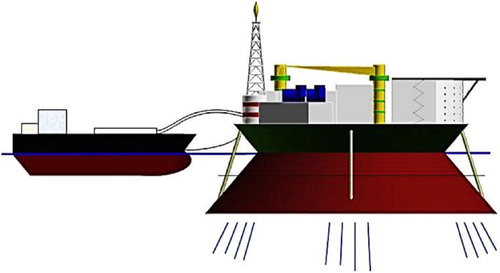
The sandglass-type FPSO has better hydrodynamic performance than the ship-type or cylindrical floating body, hence can have greater adaptability for extreme ocean conditions and higher operation effectiveness and safety (Wang et al. Citation2016).
Cross sections of sandglass-type FPSO discussed in this paper are represented schematically in Figure . The main dimensions of considered FPSO are provided in . The displacement and draft of four types of sandglass-type FPSO are the same. The plane x-y is defined as cross section plane. Positive z-axis is directed vertically upward.
Figure 2. Shape parameters and four cross sections of sandglass-type floating body.
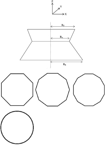
Table 1. Main parameters of sandglass-type floating model.
3. Governing equations
3.1. Theoretical formulation
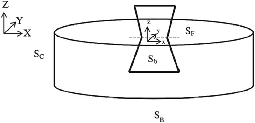
For the wave diffraction problems, the coordinate system and floating body are illustrated in Figure . Two coordinate systems have been defined based on right-handed Cartesian coordinate system. One is the space-fixed coordinate system, OXYZ, located on still water level and another is floating body coordinate system, oxyz, located on the body’s centre of gravity and moves with it. The fluid boundary surface S is composed by the mean position of the body Sb, mean free surface Sf, horizontal bottom surface SB and the far field artificial boundary-less surface Sc.
Figure 3. Graphical set-up of geometry and computational domain.
It is assumed that the wave heights are sufficiently small, so the linear wave theory is applicable. Also, the water is assumed to be an incompressible and inviscid fluid with irrotational motion. Accordingly, the fluid domain is governed by the velocity potential ϕ satisfying the Laplace equation with suitable boundary conditions (Zhang et al. Citation2010; Wang et al. Citation2015).
(1)
(1)
Kinematic free surface condition
(2)
(2)
Dynamic free surface condition
(3)
(3)
Seabed condition
(4)
(4)
Body condition
(5)
(5)
where ϕ and η represent velocity potential and free surface elevation respectively. In addition, a proper far-field condition should be implemented to avoid the unwanted wave reflection from the downstream end of the domain (Feng et al. Citation2015).
(6)
(6)
The pressure on the body,
, can be calculated by using the Bernoulli equation. The hydrodynamic forces,
, and moments,
, can sequentially be obtained by integrating the pressure over the wetted body surfaces.
(7)
(7)
(8)
(8)
(9)
(9)
3.2. Solution model
In the present paper, the numerical potential flow solver based on BEM is implemented. An accurate and efficient computational analysis of wave–body interactions is important in the design of offshore structures and marine vessels. Among various numerical approaches, the panel method, a kind of BEM, is widely used for the numerical prediction of offshore structure responses. In order to provide an accurate approximation of each patch, a set of small elements are defined, which are called panels. These panels are curved surfaces in physical space. Depending on the accuracy requirements, the size of each panel can be modified (Feng et al. Citation2015).
In this paper, the hydrodynamic behaviour of sandglass-type FPSO in regular wave is calculated by the commercial ANSYS/AQWA software (Ansys Citation2012) which is widely used in the offshore industry. This is capable of carrying out static and dynamic simulations in both the frequency and the time domain. Basically, the hydrodynamics of this simulation tool are derived from a potential flow theory with a linear diffraction model. The hydrodynamic forces are composed of radiation and wave excitation forces (including diffraction and Froude–Krylov forces). The equation of motion describing the response of the flexible structure to external excitation is mentioned in Equation (10).
(10)
(10)
(11)
(11)
where
,
,
,
denote the mass, added mass, structural linear damping and stiffness respectively in the form of N×N matrices. The N×1 vectors
,
, and
represent the structural displacements, velocities and accelerations, respectively. The column vector F denotes the external forces and N is the number of degrees of freedom assigned to the structure. RAO, which is the ratio between FPSO motions and wave amplitudes, can be driven for heave and pitch motions as in Equations (12) and (13).
(12)
(12)
(13)
(13)
4. Numerical model validation
In order to verify the process of obtaining the hydrodynamic properties, the study done by Wang et al. (Citation2016) experimentally and numerically using Wamit software, is repeated here with ANSYS/AQWA software, and the heave and pitch RAO motions results are compared as shown in Figure . Wamit is a computer program for computing the loads and motions of offshore structures in waves. It is based on the linear and second-order potential theory. The velocity potential is solved by means of boundary integral equation method (Lee Citation1995). The characteristics of sandglass-type FPSOs used for validation are presented in Figure and .
Figure 4. Hydrodynamic model of new sandglass-type floating model used for validation (Wang et al. Citation2016).
Table 2. Shape parameters of sandglass-type floating model for validation.
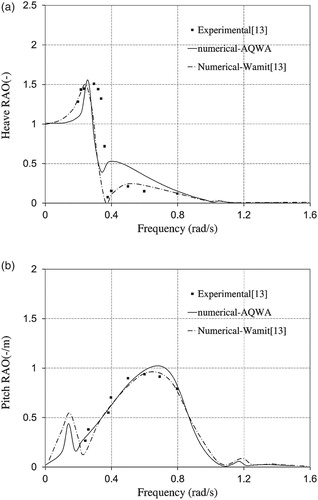
Figure shows the variation of normalised heave (5A) and pitch (5B) RAO motions and compares the results between the present calculation method and the Wang et al. (Citation2016) solution, on a uniform sandglass-type FPSO. Furthermore, from Figure (A), it can be seen that the maximum peak of heave motion RAO is totally located in the frequency range of 0.2–0.3 rad/s. It increases to its maximum value of 1.55 in frequency of 0.25 rad/s and sharply decreases in both sides. This value for experimental study is about 1.5. Therefore, the percentage of variation for current numerical method and experimental data is negligible. Figure (B) shows the comparison of pitch motion RAO versus experimental and numerical methods. It can be found that there are two peaks of amplitudes for normalised pitch motion which occurs in a frequency near to 0.1 rad/s and also at a frequency of 0.69 rad/s. The maximum value in frequency of 0.69 rad/s for pitch motion reaches to 0.94 degree/m for experimental method and 1.02 degree/m for present numerical method. As a result, it is obvious that the difference of results by present numerical method based on BEM and experimental and numerical results of Wang et al. (Citation2016) is very small, which shows that the results agree with each other very well. So the present numerical method can be used with suitable accuracy for hydrodynamic calculation of similar issues.
Figure 5. Comparison of heave (5A) and pitch (5B) RAOs of sandglass-type FPSOs versus different methods.
5. Numerical results and discussions
In this section, the effect of four types of cross section on hydrodynamic behaviour of sandglass-type FPSO has been investigated in both deep water and shallow water. In order to compare the results with each other, some input data such as displacement and draft have been kept the same. An RAO represents the non-dimensional response of a system to a small-amplitude incident wave in the direction of the X coordinate axis. The model is subjected to regular waves with a wave frequency in the range of 0–1 rad/s with 0.2 increments. It is clear that pitch and heave motions are most prominent in 180-degree waves, so in this article, discussion is about these motions.
Elements indicate that the diffraction elements are located below the still water level. Elements only situated above the still water level are also applied. By analysing the mesh sensitivity and considering the effect of computation precision and speed for four cross sections, combined meshes with numbers listed in are taken on the surface of the floating body.
Table 3. Mesh characteristic of sandglass-type FPSOs with different cross sections.
5.1. Deep water simulation
In this section, a three-dimensional problem was analysed to investigate the influence of small amplitude waves in deep water. Numerical results for the hydrodynamic responses of four types of cross sections of sandglass-type FPSO in regular waves are presented as follows.
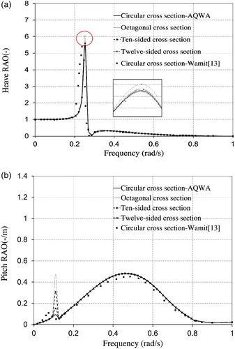
Figures presents the comparison of Heave (6A) and Pitch (6B) motions of four cross section forms and the results obtained for circular cross section with Wamit software that was presented by Wang et al. (Citation2016). It is obvious from Figure (A) that, FPSOs with octagonal, 10-sided, and 12-sided cross sections show the maximum value of heave motion of 6.03, 5.59 and 5.39 respectively. Therefore, the percentage of variation of maximum amplitude for these non-circular cross sections in comparison to circular one with maximum amplitude of 5.47, is about 9.28, 2.2 and −1.46% respectively. Thus, it is obvious that an FPSO with 12-sided cross section produces less vertical amplitude compared to circular one. In addition, the differences between the maximum heave values of the 10-sided and octagonal cross section units and circular ones are negligible too. While for pitch motion, the structures behave in another way (Figure (B)). In this motion, there are two peaks of amplitude for any cross section (Frequencies of 0.1 and 0.69 rad/s). Based on Figure (B) for pitch motion, in first frequency (0.1 rad/s), the variation of maximum amplitude of pitch motion for non-circular cross sections are significant. This value for circular cross section is about 0.093 degree/m while this increases to 0.15, 0.3 and 0.47 degree/m for 10-sided, 12-sided and octagonal cross sections respectively. In addition, at a frequency of 0.69 rad/s, the maximum amplitudes of pitch motion for all cross sections are very close and the differences are negligible. Therefore, it can be concluded from the results that, an FPSO with a 10-sided cross section matches very well with that with circular cross section in pitch motion. However, while an FPSO with a 12-sided cross section has reached a lower heave amplitude, the pitch motion of that in first frequency increases significantly in comparison to that with a circular cross section. As a whole, it is clear that the 10-sided cross section reaction is closer to the circular cross section unit in heave and pitch motions. Also, heave and pitch motions of circular cross section that have been investigated by AQWA and Wamit, produced similar results and it shows two different methods proves each other in a positive way.
Figure 6. Comparison of heave (6A) and pitch (6B) RAOs of sandglass-type FPSOs versus different cross sections in deep water.
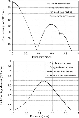
The influence of cross section area and shape of sandglass-type FPSO on normalised hydrodynamic heave and pitch exciting forces can be seen in Figure . As it is shown, there isn’t any significant difference in results obtained by AQWA for four cross sections with the same draft and displacement.
Figure 7. Comparison of heave (7A) and pitch (7B) exciting forces of sandglass-type FPSOs versus different cross sections in deep water.
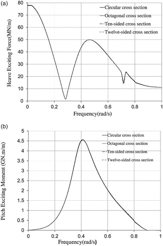
The minimum and maximum values of normalised heave exciting forces occurring in 0.27 and 0.48 rad/s are 5.49 and 49.69 MN/m respectively. Results variation for different cross sections are very small and negligible (Figure (A)). Also, normalised pitch exciting moment presents in a similar manner for all types of cross sections and the maximum amount of this moment in a frequency of 0.4 rad/s is about 4.566GN.m/m (Figure (B)).
Therefore, it can be concluded from the above results that noncircular cross sections present operational conditions in regular waves in deep water comparable to circular ones.
5.2. Shallow water simulation
Numerical investigation in the previous section is repeated in this part for structure responses in shallow water to research the influence of water depth on sandglass-type FPSOs with four different cross sections operating in regular waves. The comparison of heave and pitch motions of four cross sections has been demonstrated in Figure (A,B). It is clearly observed that FPSOs with different cross sections have similar trends in water with finite depth. However, the maximum amplitudes of motion in water with limited depth differ significantly when compared to those in deep water.
Figure 8. Comparison of heave (8A) and pitch (8B) RAOs of sandglass-type FPSOs versus different cross sections in shallow water.
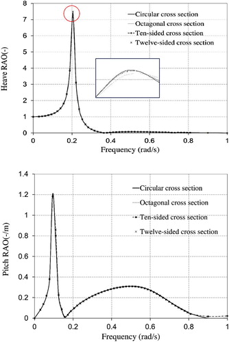
Figure (A) shows that the lowest value of maximum figures of heave motion is related to structure with 10-sided cross section with amplitude of 7.18. However, the differences between values of all cross section units are negligible. In spite of this similarity, the maximum amplitude of heave motion for FPSOs operating in shallow water has changed considerably in comparison to that in deep water such as the amplitude of 10-sided cross section that has increased from 5.59 in deep water to 7.17 in water by finite depth.
This issue is slightly different for the pitch motion of FPSO. According to Figure (B), the maximum value of pitch motion in first frequency (0.1 rad/s) varies from 0.15 degree/m in deep water to 1.18 degree/m in shallow one. In contrast, this figure decreases 35% and reaches to 0.31 degree/m from 0.48 degree/m. As a result, it is obvious that the floor of sea affects the motions of structures and changes them significantly. The influence of the cross section shape of sandglass-type FPSO on normalised hydrodynamic heave and pitch exciting forces in shallow water can be seen in Figure (A,B). As it is shown, similar to deep water, the values of exciting force and moment of all of cross sections are the same with this difference that, in shallow water the maximum values of force and moment are decreased in comparison to deep water. These differences of force are about 64.7% and 14.5% for minimum and maximum values (Figure (A)) respectively and 35.7% for moment (Figure (B)).
Figure 9. Comparison of heave (9A) and pitch (9B) exciting forces of sandglass-type FPSOs versus different cross sections in shallow water.
Therefore, it can be concluded from the above results that, by changing the shape of cross section of FPSO with equal displacement and draft, the difference between heave motion in both deep and shallow water is negligible. The variation of pitch amplitude at first frequency has some significance. The 10-sided cross section has the nearest value of pitch motion to circular cross section. Also, the amount of heave and pitch values in the first critical frequency increase significantly in shallow water compared with deep water. So, by considering both motion behaviour and manufacturing simplicity it is suggested to use the 10-sided non-circular cross section form instead of circular cross section in sandglass-type FPSOs.
6. Conclusion
The work reported in this paper has considered the effect of four different cross sections on motions and forces acting on sandglass-type FPSOs in deep and shallow waters. The BEM method based on ANSYS/AQWA software was utilised to study the motion of FPSOs in regular waves. The current numerical model was validated with a circular sandglass-type FPSO by experimental method carried out by Wang et al. (Citation2016). This comparison indicated that the BEM method results were in good agreement with the experimental values. So, the BEM model has been used to investigate the effect of cross section shape on FPSO hydrodynamic behaviour. The final results can be summarised as follows.
The maximum value of heave motion in both deep and shallow water occurred at frequencies between 0.2 and 0.3 rad/s. In this domain in deep water, the octagonal cross section had the highest maximum amplitude of heave motion RAO of about 6.03, while the lowest maximum value was 5.39 for the 12-sided cross section. Also, the 10-sided and circular cross section units had maximum amplitudes of 5.59 and 5.47 respectively. Obviously, the percentage of variations were negligible. Octagonal, 10-sided and 12-sided cross sections differed by, 9.0, 2.2 and 1.4% in comparison to a circular cross section.
The pitch motion RAO of the four cross sections presented different results in deep water for frequency near to 0.1 rad/s. In this frequency, the maximum amplitude of octagonal and 12-sided cross sections peaked at 0.48 and 0.31 degree/m respectively. However, the 10-sided cross section behaved similarly to the circular one. The maximum amplitude of pitch motion for a 10-sided sandglass-type FPSO reached to 0.15 degree/m in comparison to circular sandglass-type FPSO which was about 0.1 degree/m. In the second frequency which was near to 0.65 rad/s. the variation of maximum pitch RAOs for all cross sections was negligible.
In shallow water, the maximum amplitude of heave motion occurred to the octagonal cross section unit. It was about 7.52 in comparison to 10-sided cross section unit with amplitude of 7.17. As a result, 10-sided cross section had the decrease in the maximum value of heave motion RAO about 3.1%.
The maximum value of RAO pitch motion in shallow water for all of cross section was almost the same and the variation was very small. The minimum value was near to 1.11 for octagonal cross section and the maximum one attached to circular cross section with value of 1.20. In the frequency of 0.65 rad/s, the differences were negligible in shallow water. The heave and pitch exciting force variation in both deep water and shallow water for all cross sections was negligible.
Another important issue that has been considered in this article was how the amplitude of heave and pitch motions and exciting forces varied when a sandglass-type FPSO with different cross sections moved from deep water to shallow one. As it was obtained, the maximum amplitude of RAO heave motion for circular cross section in deep water computed 5.47 compared to 7.41 in shallow water (26% increased). In addition, this variation for 10-sided cross section units reaches to about 22% (from 5.59 to 7.18). As a result, FPSOs experience higher values of motions in water with finite depth. In shallow water and in the first frequency of pitch motion (0.1 rad/s), FPSOs with different cross sections oscillate with the greater range of pitch motion than that in deep water (1.18 and 0.3 respectively for 10-sided cross section). But this issue is different in the second frequency and the maximum amplitude of pitch motion decreases significantly in water with finite depth (variation from 0.48 to 0.3 degree/m). By comparing the data obtained, it can be concluded that FPSOs with different cross sections can be operated better in regions with infinite depth.
Based on the numerical results presented in this paper, it is quite evident that the behaviour of 10-sided cross section units is similar to circular cross section units in both heave and pitch motions with the same displacement and draft. Therefore, because of manufacturing simplicity, it is recommended to use these cross sections instead of circular one by adding some auxiliary instrument to control unsuitable motions like pitch motion in the first critical frequency.
Disclosure statement
No potential conflict of interest was reported by the authors.
References
- ANSYS. 2012. AQWA user manual. Canonsburg, PA: ANSYS.
- Chen JM, Sun Y, Zhang P. 2013. Dynamic response analysis of FPSO based on SESAM. Adv Mater Res. 694–697:267–270.
- Feng A, Chen ZM, Price WG. 2015. A desingularized Rankine source method for nonlinear wave–body interaction problems. Ocean Eng. 101:131–141. doi: 10.1016/j.oceaneng.2015.04.002
- Heurtier JM, Buhan P, Fontane E, Cunff C, Biolley F, Berhault C. 2001. Coupled dynamic response of moored FPSO with risers. The 11th International Offshore and Polar Engineering Conference; Jan 17–22; Stavanger, Norway.
- Hong YP, Wada Y, Choi YH, Kim SE. 2009. An experimental and numerical study on the motion characteristics of side-by-side moored LNG-FPSO and LNG carrier. The 19th International Offshore and Polar Engineering Conference; Jul 21–26; Osaka, Japan.
- Kim MH, Koo BJ, Mercier RM, Ward EG. 2005. Vessel/mooring/riser coupled dynamic analysis of a turret – moored FPSO compared with OTRC experiment. Ocean Eng. 32(14–15):1780–1802. doi: 10.1016/j.oceaneng.2004.12.013
- Lee CH. 1995. WAMIT theory manual. Issue 95. Part 2 of Report. Cambridge (MA): Institute of Technology. Department of Ocean Engineering.
- Nam BW, Kim Y, Hong SY. 2016. Time-domain simulation of berthing problem between FPSO and shuttle tanker in waves. Appl Ocean Res. 58:49–61. doi: 10.1016/j.apor.2016.03.010
- Nishanth R, John VK, Whyte A. 2016. Dynamic behavior of FPSO in Kikeh field under different loading conditions. ARPN J Eng Appl Sci. 11(4):2302–2307.
- Pascoal R, Guedes Soares C, Facon G, Pétrié F, Vaché M. 2004 Jun. Hydrodynamic analysis and motions of the OCTOPLUS platform. 23rd International Conference on Offshore Mechanics and Arctic Engineering; Vancouver, British Columbia, Canada.
- Vijayalakshmi R, Panneerselvam R. 2012. Hydrodynamic response of a non-ship-shaped FPSO vessel with damping plates. J Mar Sci Technol. 17:187–202. doi: 10.1007/s00773-012-0162-5
- Wang L, Tang H, Wu Y. 2015. Simulation of wave-body interaction: a desingularized method coupled with acceleration potential. J Fluids and Struct. 52:37–48. doi: 10.1016/j.jfluidstructs.2014.08.009
- Wang WH, Du YZ, Wang LL, Huang Y. 2017. Wave- free characteristic of heave motion response for new sandglass-type model. J Sh Offshore Struct. 13(2):181–193. doi: 10.1080/17445302.2017.1350932
- Wang WH, Du YZ, Wang LL, Yao YX, Gao H, Huang Y. 2017. Experimental analysis on behavior in wave for sandglass-type floating body. J Sh Offshore Struct. 12(3):443–441.
- Wang WH, Wang LL, Du YZ, Yao YX, Huang Y. 2016. Numerical and experimental analysis on motion performance of new sandglass-type floating body in waves. J Mar Struct. 46:56–77. doi: 10.1016/j.marstruc.2015.12.002
- Wang WH, Yao YX, Ye MS, Wang LL, Huang Y. 2015. Research on design scheme and hydrodynamic performance of floating body based on sandglass-type FDPSO. Sh Offshore Struct. 11(5):540–550. doi: 10.1080/17445302.2015.1031587
- Wichers JEW. 1996 Dec. Combining extreme metocean parameters on SPM moored tankers. Chennai (India): Int Conf in Ocean Eng. IIT Madras.
- Yao YX, Wang W, Huang Y. 2014. Concept design of a new sandglass- type floating production storage and offloading system. J Shanghai Jiaotong Univ. 48(4):558–564.
- Yao YX, Wang WH, Huang Y, Ye MS. 2015. Analysis on deep-water mooring system of sandglass-type FDPSO. J Shanghai Jiaotong Univ. 20(4):395–402. doi: 10.1007/s12204-015-1578-y
- Zhang X, Bandyk P, Beck RF. 2010. Sea-keeping computations using double-body basis flows. Appl Ocean Res. 32:471–482. doi: 10.1016/j.apor.2010.10.003