
 ?Mathematical formulae have been encoded as MathML and are displayed in this HTML version using MathJax in order to improve their display. Uncheck the box to turn MathJax off. This feature requires Javascript. Click on a formula to zoom.
Abstract
A lifting motor pump for deep-sea mining was proposed as a researching object. First, the structure and design method of this pump was introduced. Second, the simulating computations of the impeller in this pump were conducted at different working processes. Finally, the experiment of a two-stage lifting motor pump was conducted in the process of work to prove the applicability of this new lifting motor pump for deep-sea mining.
1. Introduction
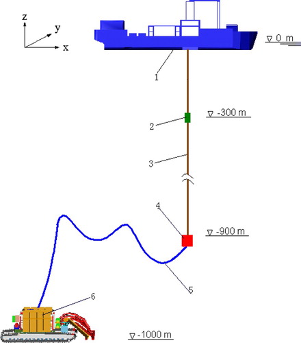
There are a large number of mineral resources in deep-sea, such as Manganese Nodules, Cobalt-rich Crust and Massive Sulphide and so on. Most of the mineral resources are deposited in the depth of 1500–3000 m of the seabed (Gao Citation2009). The exploitation of deep-sea mineral resources has been a national strategic objective for many countries, such as China, Australia and German. Deep-sea mining must rely on the equipment adaptable to extremely harsh operating environments of deep-sea and one of the key equipment is used in transporting mineral resources from seabed to sea surface. In three major deep-sea mining systems developed internationally, the pipe lifting system for deep-sea mining has the most application prospects. The pipe lifting system for deep-sea mining is shown in Figure .
Figure 1. Pipe lifting system for deep-sea mining. (1) Mining vessel; (2) Lifting motor pump; (3) Riser pipe; (4) Middle bin; (5) Soft pipe; (6) Collector.
Lifting motor pump, as key equipment for the pipe lifting system, plays a decisive role in improving the reliability and service life for the deep-sea mining system. The lifting motor pump for deep-sea mining is a special slurry pump, which should meet the characteristics of high pressure, no clogging, high-head wear resistance and efficiency. In addition, its flow path should pass through coarse particles. In terms of the research of the design and performance of the slurry pump, many scholars have done outstanding works. Roco and Nair (Citation1986) obtained the relationship between the performance of the slurry pump with the size and concentration of the particle in solid–liquid two-phase flow by the slurry pump experiment. Graham LJW et al. (Citation2009) calculated the performance of the centrifugal slurry pump in the case of homogeneous suspension and non-homogeneous suspension. Chi-Ho Park et al. (Citation2009) carried out numerical simulation for the flow characteristics of solid––liquid two-phase flows and liquid single-phase flow in a multistage lifting pump by CFD software. Zhang et al.(Citation2013) researched the adaptation relationship between impeller and volute of the slurry pump by particle imaging technology. Tao et al.(Citation2014) carried out numerical simulation for the wear of a slurry pump based on the model of Euler multiphase flow, which also confirmed the accuracy of the model by experiment.
The research achievements mentioned earlier were based on the ordinary slurry pump on the ground. Although these achievements have a certain reference more or less for the study of deep-sea lifting motor pumps, the performance of the lifting motor pump designed according to this method can not meet the requirements for deep-sea mining. Therefore, it is necessary to further research the design method of deep-sea lifting motor pump.
In this study, a new structure of lifting motor pump was proposed. Numerical simulation based on CFD software was used to predict and analyse the pump performance. A lifting motor pump was manufactured according to the structure proposed in this paper, and the characteristic curves of the pump were obtained by performance experiment.
2. A new structure of the lifting motor pump
The lifting motor pump was designed according to the technical requirements for 1 km depth of the sea. It includes total head is more than 160 m H2O, single-stage head is more than 40 m H2O, the maximum volume concentration of mineral pulp is 10%, the design flow is 432 m3/h, efficiency is not less than 45% and the rated rotation speed of the motor is 1450 r/min. Also, the mineral density is 2000 kg/m3, and the mineral particle size is less than 20 mm.
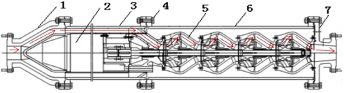
The structure of the lifting motor pump proposed in this paper is shown in Figure , which consists of seven main components: (1) Flange of Suction, (2) Motor, (3) Annular channel, (4) Nut and bolt, (5) Multistage pump, (6) Pump barrel and (7) Flange of spit out. The shaft of the multistage pump was connected rigidly with the shaft of the motor by the sleeve coupling. The primary impeller of the multistage pump was connected to the annular channel, and the final guide vane of the multistage pump was connected to the flange of spit out by bolts. The flange of suction and the flange of spit out were connected to riser pipes.
Figure 2. Structure of the lifting motor pump. (1) Flange of Suction; (2) Motor; (3) Annular channel; (4) Nut and bolt; (5) Multistage pump; (6) Pump barrel; (7) Flange of spit out.
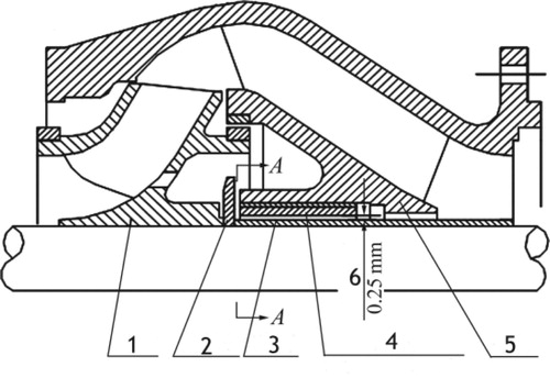
Impeller and guide vane as important over-current components of the pump, which directly affect the pump’s performance. The structure of the impeller and guide vane proposed in this paper is shown in Figure . The inlet diameter of the impeller is calculated as follows:
(1)
(1) where D1 is the inlet diameter of the impeller; Q is the flow of pump; n is the rotating speed of the motor; k0 is the coefficient related to the motor rotating speed, the range is from 3.5 to 5.5.
Figure 3. Cross-section of the impeller and guide vane. (1) Impeller; (2) Fender; (3) Axle sleeve; (4) Sliding bearing; (5) Guide vane; (6) Running gap.
The outlet width of the impeller is calculated as follows:
(2)
(2) where b2 is the outlet width of the impeller; Q and n are the same as in Equation (1); kb2 is the coefficient, which is defined in Equation (3):
(3)
(3) where
is the specific speed, which is calculated as follows:
(4)
(4) where H is the head of the pump; Q and n are the same as in Equation (1)
The outside diameter of the impeller is calculated as follows:
(5)
(5) where kD2 is the coefficient, which is defined in Equation (6).
(6)
(6)
The blade number of the impeller is defined in Equation (7).
(7)
(7) where β1 and β2 are the inlet angle and the exit angle of the impeller, respectively.
The geometric parameters of the guide vanes are related to the impeller. The maximum diameter of the inner streamline in the guide vane D3, and the maximum diameter of the outer streamline in the guide vane D4, and the blade number of the guide vanes are, respectively, expressed as follows:
(8)
(8)
(9)
(9)
(10)
(10)
3. Performance simulation of the impeller based on CFD
The impeller is the most important part of the lifting pump used at deep-sea mining. Its shape, flow and rotating speed have an immense impact on pump’s performance. With the development of computational fluid dynamics (CFD), numerical simulation has become one of the main methods to study pump performance.
In this paper, the geometric model of the impeller was made by the design tool of the interactive rotary blade in CFD software. In the simulation process, the calculation model of Particle Transport Solid was used to simulate the two-phase flow, and the RNG k-Epsilon model was used to simulate the turbulence, and the Finnie model was used to simulate particle wear. In addition, to track the trajectory of particles, the interaction between the solid phase and the liquid phase was carried out by full coupling.
3.1. Effect of the exit angle of the vane on impeller performance
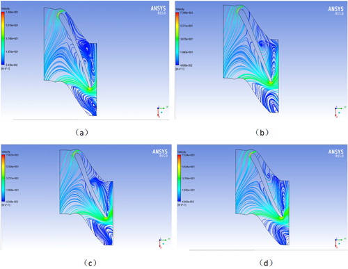
When the working flow of the pump is 432 m3/h, and the mass concentration of the particles is 10%, in the case of other geometric parameters unchanged, 20o,30o, 40o, 50o four different exit angles of the vane were selected as the analysis object. The pressure and velocity of the lifting motor pump were calculated by the Mass flow average function in Computational Fluid Dynamics X (CFX). The results show the head, the total export pressure and the exit speed of the pump all decrease with increase in the exit angle of the vane. Also, the efficiency of the pump also decreases with the increase in the exit angle of the vane. It indicates that the exit angle of the vane has a huge impact on the head and efficiency of the pump.
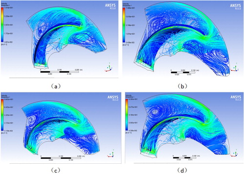
Impeller streamline distribution at a different exit angle of the vane is shown in Figure . At the front edge of the impeller exit and the middle of the pressure surface of the impeller, there are varying degrees of eddy current. In addition, the larger the exit angle of the vane, the more smooth the streamline in the impeller.
Figure 4. Impeller streamline distribution at different exit angles of the vane. (a) 20°, (b) 30°, (c) 40°, (d) 50°.
3.2. Effect of particle size on impeller wear
There are varying degrees of impeller wear due to the solid particles that collide on the impeller continuously, which is mainly related to the velocity and mass of the solid particles when the solid particles collide on the impeller. Because the velocity of the particles collides on the impeller is related to the force and mass of the solid particles in the continuous liquid, and the mass of the solid particles is directly related to the solid particle size, this means that the impeller wear is directly related to the solid particle size.
When the speed of the motor is 1450 r/min, the movement trajectory of particles with different sizes in the impeller is shown in Figure . The smaller the particles size, the more frequent collide on the impeller. The wear at the impeller tail is more severe than its head as the particles at the tail collide faster.
Figure 5. Movement trajectory of particles with different sizes in the impeller. (a) particles size is 1.5–10 mm. (b) particles size is 10–20 mm. (c) particles size is 20–30 mm. (d) particles size is 30–40 mm.
3.3. Effect of the motor rotating speed on impeller performance
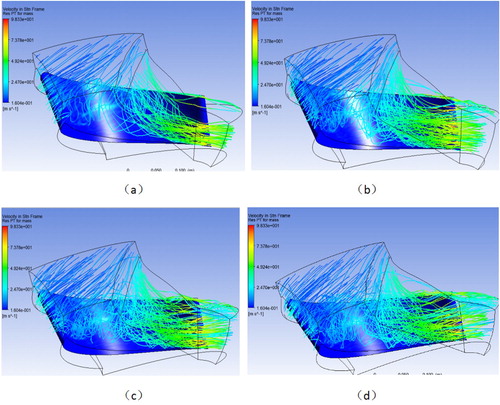
When the exit angle of the vane is 20o and the flow rate of the pump is 432 m3/h, the three-dimensional streamline in the impeller at different speed is shown in Figure . There was serious eddy between adjacent vanes because the fluid is squeezed of the blades at the first stage and sucked of the blades at the latter stage. The squeezing action of the impeller is greater than the suction action with the increase in the rotating speed of motor. The faster the rotating speed, the more obvious the action. The head of lifting motor pump escalates with the increase in motor rotating speed, the head at speed is 1450 r/min is nearly 2.5 times of the head at speed is 950 r/min. Although the increase of the motor rotating speed can increase the head of the pump, it also increases the wear of the pump.
Figure 6. The three-dimensional streamline in the impeller at different motor speeds. (a) the speed of motor is 950 r/min. (b) the speed of motor is 1450 r/min. (c) the speed of motor is 1750 r/min. (d) the speed of motor is 2050 r/min.
4. Manufacture and experiment of the lifting motor pump
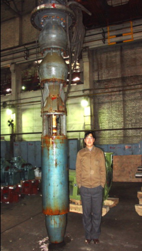
According to the design method of the lifting motor pump mentioned in this paper, a two-stage lifting motor pump for deep-sea mining was manufactured. The two-stage lifting motor pump is shown in Figure . The characteristic curves and relevant data of the two-stage lifting motor pump were obtained by an experiment, and the accuracy of the structure design and hydraulic calculation model for the lifting motor pump were verified.
Figure 7. Two-stage lifting motor pump.
During the experiment, the head, rotating speed, flow, motor power of the lifting motor pump were measured by intelligent instrumentation, such as pressure a transmitter and torque measuring instrument. The experiment was carried out at five different rotating speeds according to the experiment rule of the pump, which is rated speed n = 1450 r/min, and frequency conversion speed n = 950, 1250, 1750, 2050 r/min.
When the motor rotating speed of n = 1450 r/min, the volume concentration of mineral pulp is 10%, and the maximum particle size is 20 mm, the characteristic curves of the two-stage lifting motor pump for deep-sea mining are shown in Figure . The two-stage motor pump head is 82 m when the flow rate is 432 m3/h. It indicated that the head-flow characteristics of the pump meet the design requirements. Besides, the changes in the power-flow characteristic curve of the pump are smooth. It can avoid the risk that the power of motor changes too much or even overloads when the flow changes suddenly and achieves the purpose of equal power design for the lifting motor pump.
Figure 8. Characteristic curves of the two-stage lifting motor pump (n = 1 450 r/min).
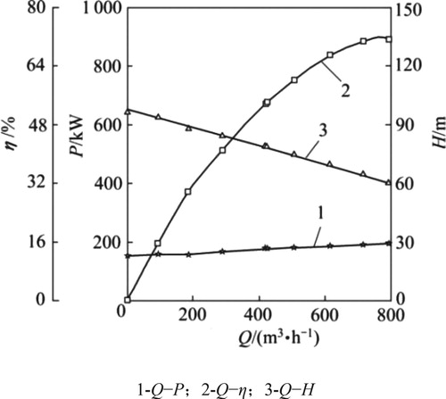
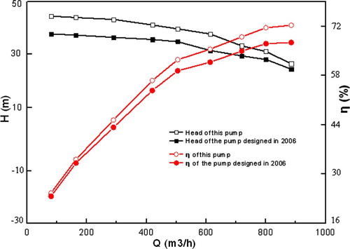
Figure shows the lift motor pump designed in China in 2006. An experiment between the lifting motor pump designed in this paper and the one designed in 2006 was compared.
Figure 9. The lifting motor pump designed in 2006.
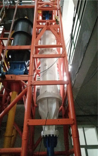
Figure shows the characteristic curves of this lifting motor pump and the one designed in 2006. As can be seen from Figure , in the case of small flow conditions, the flow-efficiency curve deviation between this lifting motor pump and the one designed in 2006 was small, but the flow-head curve deviation between the two pumps was relatively large. In the case of large flow conditions, it was just the opposite. Under all flow conditions, the efficiency of this lifting motor pump is slightly higher than the one designed in 2006.
Figure 10. Characteristic curves of this lifting motor pump and the one designed in 2006.
5. Conclusions
Through the analysis, the new lifting motor pump can meet the requirements of high-head, wear-resistance and efficiency for deep-sea mining. The impeller parameters of the pump used in the final design are as follows: inlet diameter D1 = 235 mm, outside diameter D2 = 397 mm, outlet width b2 = 60 mm, inlet angle β1 = 35° and blade number z = 3. It can greatly reduce the energy consumption of deep-sea mining as the high efficiency of the pump. The simulating computations are done based on this pump model, which can provide the basis for the optimal parameters of the impeller. According to the basis, the optimal parameters of the impeller can be improved, and then the relative optimal solution of the whole pump can be obtained.
Disclosure statement
No potential conflict of interest was reported by the authors.
Additional information
Funding
References
- Gao Y. 2009. Marine mineral resources and their distribution. Mar Environ Prot. 1:13–15.
- Graham LJW, Pullum L, Slatter P, Sery G, Rudman M. 2009. Centrifugal pump performance calculation for homogeneous suspension. Can J Chem Eng. 87:526–533. doi: 10.1002/cjce.20192
- Park J, Yoon C-H, Kang JS. 2009. Numerical Prediction of a lifting pump for deep-seamining. Proceeding of the Eighth ISOPE Ocean Mining Symposium. Chennai India. 9:20–24.
- Roco MC, Nair P. 1986. Casing head loss in centrifugal slurry pumps. Journal of Fluids Engineering. 108:453–453. doi: 10.1115/1.3242603
- Tao Y, Yuan S, Zhang J, Zhang F, Tao J. 2014. Numerical simulation and test on impeller wear of slurry pump. Trans Chin Soc Agric Eng. 30:63–69.
- Zhang D, Shi W, Chen B, Zhang L, Zhang H. 2013. Experiment and impeller and volute matching optimization of high-head submersible sewage pump. Trans Chin Soc Agric Eng. 29:78–85.