
 ?Mathematical formulae have been encoded as MathML and are displayed in this HTML version using MathJax in order to improve their display. Uncheck the box to turn MathJax off. This feature requires Javascript. Click on a formula to zoom.
Abstract
Out-of-plane impregnation and high levels of injection pressure are key strategies for cycle time reduction in Liquid Composite Molding processes. The combination of these two strategies provides a promising approach for large volume production of automotive components. In this context, a novel test system is presented, which allows the textile reaction characterization to saturated out-of-plane fluid flow at injection pressure levels of up to 200 bar. For any given engineering textile, the resulting out-of-plane permeability and total hydrodynamic compaction can be measured for different combinations of initial fiber volume content, number of layers and injection pressure. Initial tests on a conventional non-crimp fabric show a compaction-induced out-of-plane permeability decrease for pressure levels up to 95 bar, while for pressure levels between 95 and 170 bar the permeability remains constant. In other words above 95 bar, a further increase in pressure directly pays off in terms of increased flow rate. The identification of such processing windows can be very valuable for process design.
Graphical Abstract
Introduction
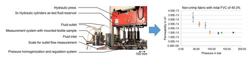
Figure 1. Textile reinforced polymers are ideal lightweight materials that can play a key role in sustainable mobility concepts. Liquid composite molding (LCM) is one of the most promising process groups for serial production, but still requires further cost reductions in order to become more competitive. In this context, the reduction of cycle times via new impregnation strategies provides a promising approach: Many components made of fiber-reinforced polymers (FRPs) are shell-like structures (e.g. automotive roof panels) with a large area-to-thickness ratio. Therefore, out-of-plane impregnation provides a way to dramatically shorten the flow paths compared to in-plane impregnation. Despite the often significantly lower textile permeability in the out-of-plane direction (about one order of magnitude), a major reduction in the impregnation time can be achieved. However, stacks of engineering textiles become significantly more sensitive to textile deformation when resin flows through them in out-of-plane direction (hydrodynamic compaction) compared to the in-plane direction [Citation1]. This effect can strongly increase the fiber volume content (FVC), which again strongly decreases the permeability. This is a challenge not to be underestimated, especially when combining out-of-plane impregnation with another main strategy for achieving shorter cycle times, namely the application of injection pressure levels of 100 bar or more. While the sensitivity to compaction is challenging even for injection pressure levels below 20 bar, it becomes even more relevant at such high pressure levels. Detailed insights into textile reactions to out-of-plane flow can support an effective process design. In this context, a novel system for experimental impregnation tests under high pressure conditions was developed, implemented and tested.
Experimental setup
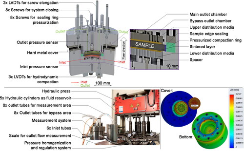
shows a CAD-model (top) and photograph (bottom left) of the novel measurement system, which is an advancement of already existing systems for textile characterization at injection pressure levels below 10 bar [Citation2, Citation3].
Figure 1. Cross-sectional CAD-model of the measurement system in testing position with mounted sample (top), test setup with measurement system and press-mounted arrangement of hydraulic cylinders for high-pressure injection (bottom left), FE-simulation of the deformation at 200 bar internal pressure (bottom right).
In general, the system allows for generation of a purely out-of-plane directed, continuous flow of a test fluid (e.g. an oil) through a textile stack sample. A constant injection pressure is generated, allowing the application of Darcýs law [Citation4], given in EquationEquation (1)(1)
(1) , for the derivation of the resulting out-of-plane permeability
of the fiber structure:
(1)
(1)
Here, is the flow rate,
is the area of the sample the fluid flows through,
is the pressure difference between the inlet and outlet pressure (which corresponds to the injection pressure due to ambient conditions at the outlet),
is the stack thickness, and
is the test fluid’s dynamic viscosity.
The 100 mm diameter circular shaped sample is placed between two distribution media (aluminum discs with a dense arrangement of holes, covered by a highly porous sintered plate), which allows pre-compaction of the specimen to a defined FVC and a uniform transverse impregnation. The fluid for the tests is initially contained within five hydraulic cylinders, mounted to a hydraulic press (max. capacity of 800 kN), which drives the fluid through a system of valves and connectors, when closed at constant speed. Here the fluid from the five cylinders unites and is regulated to the target pressure. From this point, the fluid flows into the actual test system via six tubes (diameter 10 mm) connected to a lower distribution chamber, directly below the lower distribution media, which rests on an arrangement of spacers. After flowing through the sample, the fluid passes through the upper distribution media and finally the upper distribution chamber, before it flows out of the device via 16 tubes (diameter 6 mm) to impede pressure build-up. The upper distribution chamber is divided into an internal area and a surrounding edge area, as suggested by Graupner and Drechsler [Citation5]. By comparing the flow rate in both areas, possible leakages and edge effects can be detected and considered in the calculation.
The measurement starts when the complete system is filled with fluid, which is carried out at low press closing speeds to ensure low pressure levels and avoid unwanted pre-conditioning of the specimen. The target injection pressure is then set by increasing the press closing pressure and using a pressure release valve in the pressure regulation system. A pressure sensor in the lower and the upper distribution chamber measures the respective pressure levels and via an integrated temperature sensor the fluid temperature. The cylinders can hold 12 L of fluid, allowing for a test duration of approximately 100–200 s, which is enough to achieve steady state conditions for one specific inlet pressure level (constant difference between inlet and outlet sensor). By increasing the number of cylinders, this could be further increased, allowing the application of multiple inlet pressure levels during each test.
Three spring-loaded Linear Variable Differential Transformers (LVDTs) are in contact with the lower distribution media. When the specimen stack is hydrodynamically compacted, the distribution media moves, which is then measured by the LVDTs. This allows monitoring of the total compaction and possible tilting effects. The spring-loading keeps the distribution media in contact with the specimen but does not cause any significant compaction itself. To restrict in-plane flow out or into the sample (by race-tracking), the sample edge is completely sealed with a reactive silicone. Additionally, a silicone ring surrounds the sample. A metal ring is placed over the silicone ring, on which a force can be applied via eight circularly arranged screws, allowing the silicone ring to be pressed into place.
The system was developed to allow the accurate setting of test fluid injection pressure levels of up to 200 bar. The complete upper part of the system can be detached to position the sample in place. The upper and lower part of the device are held in place during the tests by an arrangement of eight screws. A finite-element (FE)-based full mechanical simulation of the stainless-steel housing showed that deformations of the cell itself are in the range of 0.01 mm (, bottom right). However, calculations on the closing screws used in the system revealed, that up to 0.2 mm could be expected. There was no space for more or larger screws in order to limit this elongation to a negligible value. For this reason, three additional LVDTs were implemented to measure the displacement of the cover relative to the housing, and therefore, the elongation of the screws under pressure. The total compaction measurement is then corrected by this value.
Test results
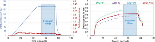
shows an example of the main data output of the system for a test using a glass fiber non-crimp fabric (Saertex X-E-444, biax ± 45°, 444 g/m2) and a rape seed oil (viscosity: 70 mPa.s at 23 °C, density: 916 kg/m³) as the test fluid. The initial FVC of the textile specimen was 49.3%, comprised of 17 layers at a 6 mm cavity height. The left diagram in shows how the pressure slowly increases until the target inlet pressure is reached. Outlet pressure does not exceed 0.05 bar, so there is no significant unwanted pressure build-up. The right diagram in shows how the hydrodynamic compaction increases accordingly, with some variation between the three LVDTs. The evaluation was carried out in the range of 50 − 70 s as highlighted by colored rectangles, when all relevant data had reached steady state conditions. In this range, the respective values were averaged over time to calculate the actual FVC and out-of-plane permeability according to EquationEquation (1)(1)
(1) . The maximum values for Reynolds number (calculated based on the equation given in Ref. [Citation6]) and shear rate (calculated by dividing the flow velocity by the channel size according to [Citation7] and considering the max. measured flow velocity of 7.8 E – 3 m/s and a min. channel size of 5 µm, i.e. roughly half of a fiber diameter) were 1.3 E – 4 and 1550 s−1, respectively. Hence, the flow remained laminar (upper limit at 1 to 10 [Citation8]) and the test fluid Newtonian in behavior [Citation9]. The temperature variation was within a range of ±0.1 °C of the average temperature for all tests reported here.
Figure 2. Output data generated by the novel setup, showing the inlet and outlet pressure development from which the pressure inlet pressure is derived (left), as well as the resulting displacement of the lower distribution media measured by the three LVDTs (corrected by the averaged displacement of the LVDTs monitoring screw elongation) and the average used for FVC calculation (right).
Using the same material and test conditions, a study on the influence of the inlet pressure was performed. The left diagram in shows the results, where each data point represents three independent tests. The error bars show the standard deviation, which is small enough to allow for the statement, that up to 95 bar there is a clear negative correlation. The results reveal an increasing FVC (54.4% at 40 bar and 56.8% at 80 bar) as the main cause, which means that in this region the effects known from low pressure are still valid. However, above this pressure level out-of-plane permeability does not further decrease in the considered range of up to 170 bar. Therefore, there appears to be a pressure range at which the injection pressure increase can be fully exploited for faster flow, as there are no additional losses due to hydrodynamic compaction. Knowing this range for a certain textile allows for optimization of the corresponding industrial processes.
Figure 3. First test results generated with the novel setup, showing how the out-of-plane permeability of a non-crimp fabric stack develops with increasing injection pressure (left) and how the initial fiber volume content affects the resulting compaction and out-of-plane permeability at an injection pressure of 95 bar (right).
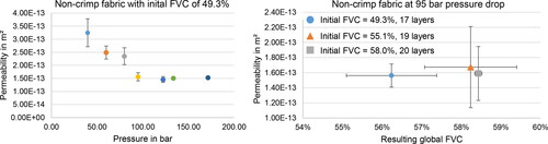
The right diagram shows the results of further tests at 95 bar inlet pressure, where the initial FVC was varied by increasing the number of layers from 17 to 19 and 20, respectively, at an equal cavity height. Again, the resulting out-of-plane permeability was similar, although the tests revealed that the initial FVC influences the resulting global FVC. It seems, that at higher pressure levels the secondary yarn – holding the glass fiber yarns together – keeps the stitching channels open, which are dominant for the overall flow regime. The increased FVC presumably results from an increased compaction of the single yarns, which show lower porosity, and thus, do not contribute much to the overall out-of-plane permeability. Hence, out-of-plane permeability can be equal although FVC is not. Besides this, it must be noted that the compared structures are inherently different, not only in terms of total FVC but also the internal FVC-distribution. It is well-known, that under transverse flow an inhomogeneous FVC distribution will occur due to inhomogeneous fluid pressure distribution [Citation10]. The results indicate, that certain compaction effects – e.g. nesting – produced in a dry state by setting a quite high initial FVC, will not necessarily be achieved via hydrodynamic compaction of an initially less compacted stack, again showing the importance of such studies.
Conclusions
A new high pressure out-of-plane impregnation permeability measurement system is now available allowing deeper investigations of process- and material-related influences on the processing behavior of textiles during high pressure LCM processes. Initial tests have revealed that there is much more to be understood in order to fully exploit the potential of this family of processes. An important field of application of the generated experimental results is to enable validation of corresponding simulation models, incorporating the complex fluid–structure interactions.
Disclosure statement
No potential conflict of interest was reported by the authors.
Data availability statement
Raw data were generated at [facility name]. Derived data supporting the findings of this study are available from the corresponding author [initials] on request.
Additional information
Funding
References
- Kabachi MA, Stettler L, Arreguin S, et al. Concurrent characterization of through-thickness permeability and compaction of fiber reinforcements. Compos A: Appl Sci Manuf. 2021;141:106203.
- Willenbacher B, May D, Mitschang P. Metrological determination of inhomogeneous hydrodynamic compaction during unsaturated out-of-plane permeability measurement of technical textiles. Adv Manuf: Polym Compos Sci. 2019;5:51–54.
- Becker D, Mitschang P. Influence of preforming technology on the out-of-plane impregnation behavior of textiles. Compos A: Appl Sci Manuf. 2015;77:248–256.
- Darcy H. Les fontaines publiques de la ville de dijon. Paris: Libraire des Corps Imperiaux des Ponts et Chausses et des Mines; 1856.
- Graupner R, Drechsler K. Quantitative transversal permeability testing-challenges and enhancements. Proceedings of the 14th International Conference on Flow Processing in Composite Materials; Lulea, Sweden; 2018.
- Shojaei A, Trochu F, Ghaffarian SR, et al. An experimental study of saturated and unsaturated permeabilities in resin transfer molding based on unidirectional flow measurements. J Reinf Plast Compos. 2004;23:1515–1536.
- Lee YM, Castro JM, Tomlinson G, et al. Analysis of flow in the RTM process. SAE Trans Sect 5: J Mater Manuf. 1989;98:65–75.
- Bear J. Dynamics of fluids in porous media. New York: American Elsevier; 1972.
- Diamante LM, Lan T. Absolute viscosities of vegetable oils at different temperatures and shear rate range of 64.5 to 4835 s – 1. J Food Process. 2014;2014:1–6.
- Klunker F, Danzi M, Ermanni P. Fiber deformation as a result of fluid injection: modeling and validation in the case of saturated permeability measurements in through thickness direction. J Compos Mater. 2015;49(9):1091–1105.