
 ?Mathematical formulae have been encoded as MathML and are displayed in this HTML version using MathJax in order to improve their display. Uncheck the box to turn MathJax off. This feature requires Javascript. Click on a formula to zoom.
Abstract
In order to improve the course control accuracy of unmanned surface vehicle (USV), a course control system based on improved active disturbance rejection control (ADRC) is proposed in this paper. The course controller designed in this paper can realize automatic course maintenance and achieve good stability of USV. The extended state observer of ADRC is used to estimate the unknown disturbance in real time and give appropriate compensation. It is difficult to set the ADRC parameters, so firefly algorithm (FA) is introduced into the ADRC algorithm to realize the self-setting of nonlinear feedback control law parameters. The simulation results show that the course control system designed in this paper can achieve precise control of the USV’s course and the system is robust.
1. Introduction
Due to the advantages of high sailing rate, low cost, and ability to replace humans in various activities under severe conditions, USV has become a research hotspot of intelligent marine equipment at home and abroad. The motion control of USV is the core content of its development. Excellent control performance is the prerequisite for the successful implementation of various tasks of USV. At present, USV have become an important platform for tasks such as search and rescue, reconnaissance, monitoring, ship escort, anti-mine and anti-submarine. The under-actuated system refers to the system that the input dimension is less than the spatial dimension, that is, the number of system inputs is less than the number of degrees of freedom of the system. USV is a typical under-actuated system (Kolmanovsky & Mcclamroch, Citation1995). Due to the characteristics of large inertia, nonlinearity and time delay, USV will encounter environmental disturbances such as wind, wave and current during navigation, which will cause USV to deviate from its set course. The course control precision of USV determines its navigation safety. How to make the USV maintain the desired course in case of interference has become the research focus for the motion control of USV.
In Caccia et al. (Citation2005), a theory of PD heading controller and line-of-sight planning algorithm was proposed. In Sukon and Manukid (Citation2006), an online self-tuning precompensation for a Proportional-Integral-Derivative (PID) controller is proposed to control heading direction of a flying robot. The online self-tuning precompensation algorithm is implemented simply by adding the precompensator to the existing conventional PID controller. In Naeem et al. (Citation2006), the course controller is designed by combining classical PID control technology and fuzzy control technology, and it is verified by simulation, and good control effect is obtained. In Kumarawadu and Kumara (Citation2007), the speed control of an unmanned vehicle under the influence of longitudinal, lateral and course coupling has been studied. At the same time, in order to ensure the stability of course motion, a speed controller based on Lyapunov function was designed. In Bibuli et al. (Citation2008), a set of course control method is designed based on Kalman filtering and PID control technology. In Bao et al. (Citation2009), the sliding mode method has been adopted to identify the parameters of the unmanned aerial vehicle motion model, and then designs a course controller using the sliding mode variable structure. In Bao et al. (Citation2009), a motion control system was designed based on sliding mode observer and sliding mode controller, which successfully solved the USV course and lateral control problems, and proved the stability and reliability of the switching control law by using Lyapunov stability theory.
In Sharma et al. (Citation2014), evaluated the design of two kinds of nonlinear autopilot based on nonlinear local control network and nonlinear model predictive control, and establishes its effectiveness in terms of power consumption. In Larrazabal and Penas (Citation2016), the performance of the course controller is improved by using backstepping control, which made the controller more accurate in maintaining the course, and its performance in the line and forward control was satisfactory. In Das and Talole (Citation2016), a design method of ship robust steering autopilot based on generalized extended state observer is proposed. The controller provides satisfactory tracking performance under the uncertainties and disturbances of matching and mismatching. In Larrazabal and Penas (Citation2016), using a genetic algorithm to design gain scheduling PID controller and fuzzy logic controller, optimize the controller parameters, and combine the two controllers for simulation comparison.
In Mu et al. (Citation2017), a non-singular fast terminal sliding mode controller is proposed based on multi-mode control theory. The chattering of the system is weakened by RBF neural network and fuzzy weighting. Finally, simulation and comparative study prove the rapidity and robustness of the proposed control method. In Wang and Han (Citation2017), a new model based on the network is proposed and gives the stability criterion. The experimental results show that the controller design based on active packet loss can effectively reduce the sway of course angle and rudder angle. In Do et al. (Citation2017), a nonlinear model of unmanned craft is established, designs a course controller based on the principle of fuzzy control, and designs an unmanned vehicle motion control system with autonomous planning capability based on the validity of the controller verified by MATLAB simulation. In Wang et al. (Citation2017), the course controller is designed based on improved fuzzy predictive control strategy and the contrast experiment is carried out to demonstrate the superiority of the designed course controller over the traditional PID controller. The simulation results verify that the control effect of the proposed control method is better than that of the conventional control method.
In Zhao et al. (Citation2018), an improved PID control method was proposed for the course control of USV, where the course maintaining effect was satisfactory and the course tracking speed was fast in the case of uncertainty. In Huang et al. (Citation2019), a controller called ADRC was proposed, which inherits the advantage of PID control independent of the specific model of the controlled object, was proposed by Mr. Han from the Chinese academy of sciences. The core idea of ADRC is to estimate the unknown disturbance inside and outside the system in real time by using the extended state observer (ESO) and give the appropriate compensation, so as to realize the reasonable control of the system.
The course control of USV with three degrees of freedom is investigated in this paper. The main contribution of this paper is to introduce FA into the ADRC algorithm to realize the self-setting of nonlinear feedback control law parameters, thereby solving the difficult problem of setting the ADRC parameters and improving the accuracy of USV course control. For this purpose, this paper introduces the mathematical model of USV, and introduces the ADRC and FA algorithms in detail. Finally, by comparing FA-ADRC and ADRC, the simulation results show that the course control system designed in this paper can achieve precise control of the USV’s course and the system is robust.
2. Modelling
2.1. Model of USV
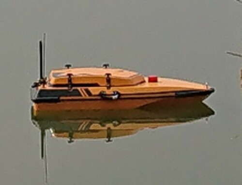
This section will introduce the mathematical model of USV. The actual USV is shown in Figure .
Figure 1. The actual USV.
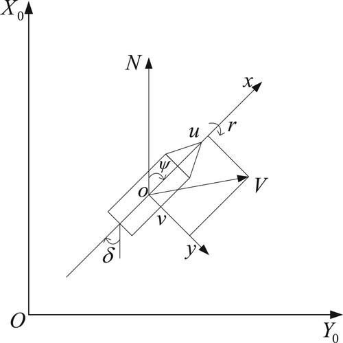
In this paper, Abkowitz’s 3-dof modelling idea is adopted (Abkowitz, Citation1964). The movement of unmanned surface vehicle includes forward movement, lateral drift and bow turning, as shown in Figure .
Figure 2. Plane movement diagram of USV, where ,
and
represent the forward speed, sway speed and yaw speed.
and
denote the course angle and rudder angle.
is resultant velocity of
and
.
is the attachment coordinate system, and
is the centre of gravity of the USV,
is the geodetic coordinate system, and
is the origin, and
represents the due north direction (Fossen, Citation1957).
This paper adopts the second-order Nomoto mathematical model (Nomoto et al., Citation1957), and the formula of the second-order Nomoto mathematical model is as follows:
(1)
(1) where
is index of cyclicity, and
is followability index.
2.2. Model of steering gear
The steering gear has nonlinear characteristics such as dead zone, hysteresis, saturation etc. These characteristics will be more or less affect the performance of the marine USV control system. The steering gear can be represented by the following model (Yang, Citation2010).
(2)
(2) where
is the command rudder Angle, and
is the steering gear time constant (generally 5.4 s for unmanned surface vehicle), and
is the steering gear control gain (usually approximately equal to 1).
Considering the actual situation of the steering gear, the rudder angle and rudder speed should meet the following constraints: ,
.
2.3. Model of external disturbance
USV will encounter wind and wave interference when sailing at sea, so in actual simulation, continuous disturbance is used to replace the current disturbance. Wind and wave interference are represented by second-order oscillation link (Yang et al., Citation2001), the formula is as follows:
(3)
(3) where
is White Gaussian Noise, and the spectral density is 3.
3. Principle of ADRC
3.1. Tracking differentiator
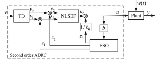
The ADRC consists of three components: the tracking differentiator (TD), the extended state observer (ESO) and the nonlinear state error feedback (NLSEF). The tracking differentiator can arrange the transition process (small error principle), which can not only quickly track the input signal of the system, but also extract the differential signal, which is very effective in solving the contradiction between rapidity and overshoot.
The core idea of the ADRC is to use the extended state observer to put the system internal disturbance and the external disturbance together as the total disturbance, estimate the total disturbance of the system in real time and give appropriate compensation, and finally a nonlinear combination is performed to generate the control quantity required by the system to achieve the control target of the controller. Taking second-order ADRC as an example, it is assumed that a class of uncertain control object is as follows:
(4)
(4) where
is the unknown function of the system, and
is the external disturbance from the system. The principle block diagram of the ADRC system is shown in Figure , where
is the input signal, and
is the control amount generated by the controller and
is the output of the controlled object.
Figure 3. Principle of ADRC.
The input signal of the actual control system is often polluted by noise, so it is difficult to obtain its differential signal. The tracking differentiator can arrange the transition process, which can not only track the input signal of the system quickly, but also extract the differential signal, which is very effective in solving the contradiction between speed and overshoot. The formula of tracking differentiator can be expressed as follows:
(5)
(5) where
is the input signal, and the
denote tracking input signal
, and the
denote tracking differential
, and
is the speed factor, which determines the speed of system tracking.
is the sampling step length, if the
of
is changed to
, the filter effect can be achieved, usually
.
Formula of discrete system time optimum control synthesis function can be expressed as follows:
(6)
(6)
3.2. Extended state observer
The core of ADRC is the extended state observer (ESO). ESO can treat the internal disturbance and external disturbance of the system as a whole. That is the total disturbance. ESO can estimate the total disturbance of the system in real time and calculate the appropriate compensation. The system with unknown disturbance, nonlinearity and uncertainty can be transformed into a standard linear integral series system, thereby reducing the workload of measuring unknown disturbances (internal disturbance and external disturbance) and improving the system efficiency of the control system. ESO formula can be expressed as follows:
(7)
(7)
In order to eliminate vibration, on the basis of a large number of experiments, Professor Han selected a nonlinear power-function with a linear section near the origin. The function is defined as whose form is given as follows:
(8)
(8) where
and
can be taken in general, in which a1 and a2 are empirical values. When the parameter
are selected reasonably, the extended state observer can observe the system and external interference, so it can be known:
.
3.3. Nonlinear state error feedback
In order to reduce the error as much as possible on the premise of system stability, Professor Han extended the PID control algorithm and proposed a nonlinear state error feedback. Assuming a second-order system, the model of NLSEF is as follows:
(9)
(9) where
,
are the state error,
,
are the feedback control gain,
is the extracted signal of nonlinear combination,
is the disturbance compensation quantity, and
is the output of ADRC.
4. Firefly algorithm
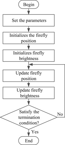
In 2009, the firefly algorithm (FA) proposed by Cambridge University professor Xin-She Yang by studying the behaviour of fireflies in nature. Professor Yang was inspired by the behaviour of the luminescence and flickering, using its flash as a signal to attract other fireflies. Firefly algorithm is a kind of advanced meta-heuristic algorithm. Compared with other intelligent algorithms, the algorithm process is very clear, the principle is simple and easy to understand, the adjustable parameters are less, the implementation difficulty is low, and the actual problem is easy to solve.
The core idea of firefly algorithm is to be attracted by firefly with greater absolute brightness and update its position according to the position update formula. The principle diagram of firefly algorithm is shown in Figure .
Figure 4. Firefly algorithm principle.
Assuming that the absolute brightness of the firefly
at
is the same as the objective function value at the
,
. Assuming that there is firefly
and firefly
, the absolute brightness of firefly
is greater than that of firefly
, then firefly
will move to their positions due to the attraction of firefly
. Since the brightness of firefly
decreases with the increase of distance and air absorption, the relative brightness of firefly
to firefly
is assumed to be:
(10)
(10) where
is the light absorption coefficient, and
a constant can be taken to represent the Cartesian distance between firefly
and firefly
.
(11)
(11)
For solving a two-dimensional problem, equation (11) can be converted to:
(12)
(12) With the light intensity definition known, the next definition of attraction
, the attraction of firefly
to firefly
is:
(13)
(13)
In (13), is the maximum attraction, that is
, the attraction of the light source, normally
is 1. The absorption coefficient
has a great influence on the convergence and optimization of firefly algorithm.
As the firefly moves toward the firefly
, and the firefly
updates its location. The update formula is as follows:
(14)
(14) where
is the set number of iterations,
are the positions of firefly
and the firefly
, and
characterizes the attraction of firefly
to firefly
,
is a constant, if the value of
is too large, it may cause algorithm to oscillate, if the value of
is too small, the algorithm will not be able to efficiently perform local searches,
is a random vector obtained from uniform distribution, Gaussian distribution or other distributions. The second term of equation (14) emphasizes the effect of attraction, and the third term is the random disturbance term.
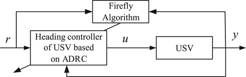
5. FA-ADRC based course controller for USV
For the course control system of USV based on ADRC, the parameters of NLSEF module are adjusted by using FA. The structure diagram of FA optimized ADRC is shown in Figure .
Figure 5. ADRC parameter setting based on FA, where is the system reference input,
is the control quantity, and
is the system output.
The integral absolute error (IAE) can be used as a scale to evaluate the performance of the system. The main feedback signal or the expected output of the system can be expressed in the form of function integral. For the SISO system, a satisfactory transition process can be obtained by using IAE as the objective function to be optimized. The objective function form is as follows:
(15)
(15) where
is the error between the actual output value of the system and its expected value.
6. Simulation experiment
The parameters of USV used in the simulation are shown in Table .
Table 1. USV parameters.
The USV Nomoto model is as follows:
(16)
(16)
The ADRC and FA-ADRC are compared in the performance analyse of the designed course control strategy. The simulation parameters of the course control strategy based on FA-ADRC are set as follows.
FA: ,
,
;
TD: ,
;
ESO: ,
,
,
;
NLSEF: ,
,
,
.
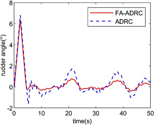
The simulation results without external interference are as follows (Figures and , Table ).
Figure 6. The curve of changing course under FA-ADRC and ADRC.
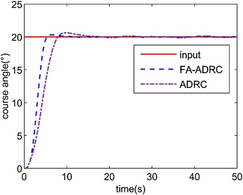
Figure 7. The curve of changing rudder under FA-ADRC and ADRC.
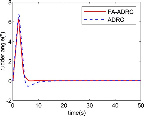
Table 2. Dynamic performance.
Based on the above data, it is not difficult to conclude that the FA-ADRC based USV course controller is more responsive, smaller overshoot and requires less energy to steer than the ADRC based system.
Simulation under parameter perturbation. At this time, ,
while other system parameters remain unchanged, the simulation results are as follows (Figure ).
Figure 8. The curve of changing course under FA-ADRC and ADRC.
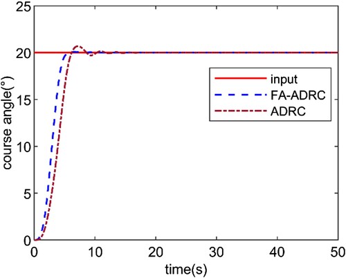
As can be seen from this figure, the ADRC-based USV course control system is sensitive to the variation of K and T parameters, while the FA-ADRC-based USV course control system has strong robustness and better system stability.
Simulation results under wind and wave interference (Figures and ).
Figure 9. The curve of changing course under FA-ADRC and ADRC.
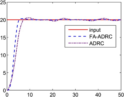
Figure 10. The curve of changing rudder under FA-ADRC and ADRC.
As can be seen from the figure, when encountering external environmental interference, the ADRC-based USV course control system is larger than that based on FA-ADRC, and the system response is slower. The safety and reliability of FA-ADRC method have been further verified. When sailing at sea, the direction control system based on FA-ADRC can meet the requirements of high precision control and safety and stability.
7. Conclusion
In this paper, according to the characters of USV was designed based on FA-ADRC USV course controller. For no one closer to the actual sailing USV environment, increased the real-time disturbance simulation and interference in the simulation. From the simulation results we can know, based on FA-ADRC controller, better stability than ADRC USV course controller and it has strong robustness, good adaptability. It can meet USV course control to the requirement of rapidity and high accuracy. In our future research, the anti-interference ability of the control model will be further enhanced. In addition, the UAV-USV collaborative system will also be considered.
Disclosure statement
No potential conflict of interest was reported by the author(s).
Additional information
Funding
References
- Abkowitz, M. A. (1964). Lectures on ship hydrodynamics-steering and manoeuvrability. Stevens Institute of Technology (Report No. HY-5).
- Bao, X., Nonami, K., & Yu, Z. (2009). Combined yaw and roll control of an autonomous boat. Proceedings of the 2009 IEEE International Conference on Robotics and Automation (pp. 188–193), Kobe, Japan, May 12-17, 2009.
- Bibuli, M., Bruzzone, G., Miskovie, N., Vukic, Z., & Caccia, M. (2008). Self - oscillation based identification and heading control for unmanned surface vehicles. Proceedings of the 17th International Workshop on Robotics in Alpe-Adria-Danube Region (pp. 1–6), Ancona, Italy, April 21-25, 2008.
- Caccia, M., Bono, R., & Bruzzone, G. (2005). Design and exploitation of an autonomous surface vessel for the study of sea-air interactions. Proceedings of the 2005 IEEE International Conference on Robotics and Automation (pp. 3582–3587), Barcelona, Spain, April 18-22, 2005.
- Das, S., & Talole, S. E. (2016). Geso based robust output tracking controller for marine vessels. Ocean Engineering, 121, 156–165. https://doi.org/https://doi.org/10.1016/j.oceaneng.2016.05.027
- Do, N. M., Vo, H. H., & Nguyen, D. A. (2017). Design and implement a fuzzy autopilot for an unmanned surface vessel. Proceedings of the International Conference on Advance Engineering Theory and Applications (pp. 454–459).December 7-9, 2017.
- Fossen, T. I. (1994). Guidance and control of ocean vehicles. John Wiley and Sons LTD.
- Huang, H., Gong, M., Sharma, S., Zhuang, Y., & Xu, D. (2019). A new guidance law for trajectory tracking of an underactuated unmanned surface vehicle with parameter perturbations. Ocean Engineering, 175, 217–222. https://doi.org/https://doi.org/10.1016/j.oceaneng.2019.02.042
- Kolmanovsky, I., & Mcclamroch, N. H. (1995). Developments in nonholonomic control problems. IEEE Control Systems Magazine, 15(6), 20–36. https://doi.org/https://doi.org/10.1109/37.476384
- Kumarawadu, S., & Kumara, K. J. C. (2007). On the speed control for automated surface vessel operation. Proceedings of the 2007 third International Conference on Information and Automation for Sustainability (pp. 135–140), Melbourne, Australia, December 4-6, 2007.
- Larrazabal, J. M., & Penas, M. S. (2016). Intelligent rudder control of an unmanned surface vessel. Expert Systems with Applications, 55, 106–117. https://doi.org/https://doi.org/10.1016/j.eswa.2016.01.057
- Mu, D., Wang, G., Fan, Y., & Zhao, Y. (2017). Modeling and identification of podded propulsion unmanned surface vehicle and its course control research. Mathematical Problems in Engineering, 2017, 1–13. doi:https://doi.org/10.3966/199115992017122806011
- Naeem, W., Sutton, R., & Chudley, J. (2006). Soft computing design of a linear quadratic Gaussian controller or an unmanned surface vehicle. Proceedings of the 14th IEEE Mediterranean Conference on Control and Automation (pp. 1–6), Ancona, Italy, June 28-30, 2006.
- Nomoto, K., Taguchi, T., Honda, K., & Hirano, S. (1957). On the steering qualities ships. International Shipbuilding Progress, 4(35), 354–370. https://doi.org/https://doi.org/10.3233/ISP-1957-43504
- Sharma, S., Sutton, R., & Motwani, A. (2014). Non-linear control algorithms for an unmanned surface vehicle. Proceedings of the Institution of Mechanical Engineers Part M Journal of Engineering for the Maritime Environment, 228(2), 146–155. https://doi.org/https://doi.org/10.1177/1475090213503630
- Sukon, P., & Manukid, P. (2006). Online self-tuning precompensation for a PID heading control of a flying robot. International Journal of Advanced Robotic Systems, 3(4), 323–330. doi:https://doi.org/10.5772/5722
- Wang, Y., & Han, Q. (2017). Network-based heading control and rudder oscillation reduction for unmanned surface vehicles. IEEE Transactions on Control Systems Technology, 25(5), 1609–1620. https://doi.org/https://doi.org/10.1109/TCST.2016.2617321
- Wang, L., Wu, Q., Liu, C., Xie, S., & Chu, X. (2017). Design method of USV course-tracker based on simulation and real vessel experiment. Proceedings of the 4th International Conference on Transportation Information and Safety (pp. 236–245), Banff, Canada, August 8-10, 2017.
- Yang, L. (2010). Study of fuzzy self-tuning steering controller for ship course. Navigation of China, 33(1), 11–15.
- Yang, C., Jia, X., & Bi, Y. (2001). Ship rudder damping and robust control. Dalian Maritime University press.
- Zhao, P., Zhang, H., & Tong, X. (2018). The design of gain scheduling PID controller of the USV course control system. Proceedings of the 2018 Chinese Automation Congress (pp. 1408–1413), Xian, China, November 30 - December 2, 2018.