
 ?Mathematical formulae have been encoded as MathML and are displayed in this HTML version using MathJax in order to improve their display. Uncheck the box to turn MathJax off. This feature requires Javascript. Click on a formula to zoom.
Abstract
Based on our previous contributions about UAV target tracking and recognition, this paper continues to do the synthesis analysis for the ellipsoidal method for the above practical problem. Given a nonlinear system or linear system, corresponding to the motion equation for the considered target, the UAV target tracking and recognition is to identify the unknown but bounded noise, then ellipsoidal method is proposed to achieve this goal. The main step for ellipsoidal method is to compute one intersection operation between one ellipsoid and a strip. Through our own mathematical derivations, this intersection part is also an ellipsoid. The centre of the final ellipsoid is deemed as the accurate state estimation from the generated ellipsoidal sequences. To alleviate the deficiency of our previous contributions, synthesis analysis for ellipsoidal method is also derived to complete the efficiency. Finally, one simulation example confirms our ellipsoidal method for UAV target tracking and recognition.
1. Introduction
Unmanned aerial vehicles (UAVs) also known as aerial robot is an aircraft with some nice properties, such as remote control, automatic, semi-autonomous and fully autonomous flight capabilities. Due to UAV's simple structure, low cost, good operation, strongly adaptive environment and load lots of equipment, research on UAV is becoming vast. Specifically, with the development of intelligent technology, sensor technology, microelectronics and digital communication, etc., some problems, existing for many years have been gradually overcome. For the aspect of military, UAV is often applied to perform tasks such as search and reconnaissance, battlefield situation monitoring and target tracking or detection. Some kinds of products of UAV have been in world war, and the more famous are listed as follows American global hawk, predator, fire scout, etc. So far, 55 countries have been equipped with UAVm it means UAV has nice development prospects in both the military and civilian fields.
About major information, that human obtain from the outside world are received through the vision system. Therefore, the vision system can bring us the ability to obtain more and enough external information. But with the development of society, human vision is unable to meet our urgent requirements on accuracy and efficiency, then human begin to develop the more advanced vision system of machine learning, helping the machine obtain real time information about the surrounding environment. The above idea is named as machine vision or computer vision. Through replying on the computer vision, the target recognition and tracking technology based on computer vision refer to the detection, recognition and tracking of the moving targets in the image sequence. Furthermore, other missions can be completed by using the computer vision for target tracking, for example, obtaining motion parameters, i.e. the position and speed of the target, and then further processing or analysing them to calculate a higher level of task. Due to the low cost of image target recognition and tracking, high accuracy, strong anti-interference ability and good operation, computer vision for UAV is widely used in many fields, which include map matching, aircraft navigation, radar image tracking, and the end of weapon projecting systems. Some characteristics of hovering and low speed cruising for the micro-rotor aircraft are benefit as an ideal carrier for the camera to efficiently expand the camera's view field. More specifically, micro-UAVs equipped with visual sensors, i.e. cameras can conduct aerial surveillance and tracking flight of ground targets, then it effectively completes some tasks, for example, traffic monitoring, anti-terrorism, anti-rot, disaster relief and maritime search or rescue, etc. UAV target tracking system based on the computer vision means one UAV with a low flying height and a camera mounted pan-tilt control system can acquire the target motion information according to the sequence od the captured images, then automatically adjust the rotation and motion of the onboard pan-fit. As a consequence, the pitch angle and the attitude of the considered UAV make the tracked target always appear in the centre of the camera's image, while using the tracking method to estimate the motion state of the target and regarding the estimated state as a feedback signal to control the considered UAV. The above process description is to let the UAV track the target, whatever ground target or flying target. Generally, computer vision is one of the hot research fields of artificial intelligence at present, and it is an emerging discipline that studies how to use the computer system to realize the human visual system and explain the existence of the world. UAV target tracking and recognition based on computer vision has developed rapidly in recent decades, but there are still many problems that need to solved urgently. For example, among them, target tracking and recognition of sequence image is a typical and extremely challenging subject. Consider the civilian aspect, the most important applications of target tracking and recognition are the security monitoring of packing lots, banks and traffic, which satisfy the high security requirements. Specifically, the video images from UAV or other multiple ground platforms provide lots of useful information, such as abnormal behaviour detection, intelligent vehicle identification and pedestrian behaviour judgement, etc. Furthermore, within the field of military, the requirement for video surveillance system is more strict, as the battle field situation is changing rapidly and more complex than the normal civilian environment. Now target tracking and recognition is more widely applied in the military development, for example, in recent years the high resolution cameras and micro TVs are installed in the USA or France.
Based on the above-detailed description about vision tracking system for UAVs target tracking and recognition, each UAV collects lots of observed data to form the image sequence through the computer vision system, then our mission, corresponding to the goal of target tracking and recognition, is to extract the most important information from these observed data or the formed image sequence, as the information for the considered target are embodied in the observed data. Then some statistical methods are applied directly from the probability theory to estimate or identify those useful information, i.e. system identification, statistical analysis, signal processing, etc. For convenience, one example is given to understand well. Assume an UAV is flying in sky, while one car is moving on the ground, the flying UAV wants to attack the moving car. First, the flying UAV needs to get some information for the moving car, so the camera, installed on the head of the flying UAV, will take lots of photos about the moving car, while guaranteeing the moving car in the centre of each photo. Second, the computer control system will deal with these photos to extract some useful information for the moving car, such as its velocity, position, mass, etc. This process corresponds to UAV target tracking and recognition, which depends on some nice estimation algorithms. To the best of our knowledge that before to the next practical engineering process, the approximated model or system is needed to express the considered plant, i.e. the moving car on the ground. Then based on this approximated model, the intrinsic computer controller system starts to use the statistical method to achieve the mission. If the approximated model is one nonlinear model, Bravo et al. (Citation2007) applies it local approximation to describe the considered system, then all existed results about linear system can be used directly. A new correlation method was proposed in Care et al. (Citation2018) to identify the unknown parameters, corresponding to the velocity for the considered target. The efficiency of this new correlation method was verified by the scenario strategy, coming from the data driven decision theory (Campi et al., Citation2021), when considering the external effects, the correlation method is not good at identifying the unknown parameters, as it is an ideal case without any external effects, so reference Care et al. (Citation2021) proposed the sign perturbed sums to achieve the recognition within the case of undermodelling factors. On other extended model, EIV system was designed to form the special target model, whose input and output are all corrupted by the statistical noise (Khoresani & Wayer, Citation2020). The above process about extracting some useful information from the observed data of image sequence is similar to the novel research control community-data driven control (De Peris & Tesi, Citation2020), where the difference is that the observed data is dealt with to get state information or the controller respectively. From the theoretical respective, the number of observed data is derived to guarantee the efficiency of the target tracking result in Xiaojing et al. (Citation2015) and Xiaojing et al. (Citation2017). Finally, our two newly published papers pave the way to deeply study this UAV target tracking and recognition. References Jianhong et al. (Citation2021) and Jianhong et al. (Citation2020) give the detailed analysis process for our continuously considered problem of UAV target tracking and recognition. Everybody, being interested in it, can refer to those two papers.
Based on above mentioned references and our two new contributions about UAV target tracking and recognition, this paper gives the recent result for the same subject, whose all variables are unknown but bounded, i.e. observed noise and observed output are all included in their own sets. Whatever linear or nonlinear form are used to be the system for the target, all useful information are the elements, existing in the system state, so the problem of UAV target tracking and recognition is mainly concerned on estimating or identifying the unknown state, which is also the mission for system identification or adaptive control. For the case of linear form with statistical description on observed or external noise, the classical Kalman filters is nice to estimate the unknown system state. Then some improved Kalman filters are proposed to achieve the state estimation for the case of nonlinear form with statistical description on noise. Here statistical description on noise means its probabilistic density function is known to each other. But you know this statistical description on noise is an ideal case, due to in practice white noise and colour noise does not exist, and they are used in only theoretical research, so to extend the theoretical research and be more practical in engineering, the case of unknown but bounded noise is considered in recent years, i.e. the considered noise is known only in one set, but nothing about its probabilistic density function. Although some sets are proposed included the noise or other physical variable, here in this paper, ellipsoid is introduced. Other existing approaches hold on the condition that external noise is one white noise, but while noise does not exist in practice. So this paper considers more extended case for noise, being unknown but bounded noise.
Generally, the main contributions of this new paper are formulated as follows.
Ellipsoidal method is proposed to estimate the unknown state, existing in the UAV target tracking and recognition. It means for the case of bounded noise, a sequence of ellipsoids are constructed to include the unknown state, then the centre of the final ellipsoid is deemed as the state estimation.
To alleviate the deficiency of our previous result in Jianhong et al. (Citation2021), synthesis analysis for this ellipsoidal method is yielded to complete the systematic analysis on the ellipsoidal method.
2. UAV target tracking system
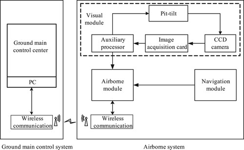
As the UAV vision tracking system ia a basis for the latter control and identification process, so here only some introduction about UAV vision tracking system is described to be the foundation. The whole UAV vision tracking system, plotted in Figure , includes two parts, i.e. the ground main control centre and the airborne navigation system, where the information is transmitted through the wireless communication module. Specifically, the ground main control centre is mainly used to monitor the flight status of UAV and detect whether the flight data is normal of not. It can send commands to control UAV at any time to prevent UAV from being damaged due to equipment abnormalities. Similarly, the airborne navigation system is mainly applied to collect the image information and navigation information and process the collect information to control the actuator, then finally the flight control and tracking task for UAV is realized. Among the whole UAV vision tracking system, the vision module is composed of a CCD camera, an image acquisition card, a pan-tilt and an auxiliary processor. Roughly speaking, the navigation module consists of some sensors such as GPS, IMU inertial devices and ultrasonic ranging modules. Within the indoor environment, GPS always fails, so the three axis accelerometer of the IMU inertial device is applied to replace that GPS. The visual module in the visual tracking system for UAV uses the collected images to process them. The choice and installation scheme for the camera, the image processing algorithm, and the computation speed all determine the performance of UAV visual tracking system. In the vision module, designed in the latter simulation example. A CCD camera is applied for image acquisition, and a single axis tilting pan tilt head is to expand the reconnaissance range of the camera. Then an image acquisition card is used to convert the analog signal into a digital signal that can be processed by the computer. In addition, an auxiliary processor is specially set up for image signal processing and pan-tilt rotation control, which will greatly improves the processing capability of the entire UAV vision tracking system.
Figure 1. UAV vision tracking system.
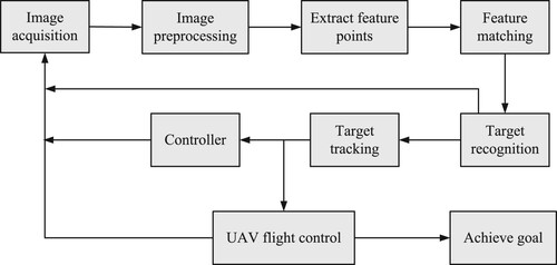
Navigation is to guide the carrier to navigate. The automatic navigation of UAV based on computer vision technology means that the UAV uses the charge-coupled component CCD camera as the sensor to obtain the image during the flight, and then analyses and understands the image, and then obtains the navigation information such as the position and motion status of the moving target. It enables the drone to have the ability to interact with the external environment, and further improves the automation level of flight control. At present, there are two main ways to form a visual navigation system: one is to install an image processor on the aircraft, and the camera collects the image signal and transmits it to the onboard processor for processing. The hardware requirements are high and the implementation is more difficult; the other is to send the image signal to the ground computer through a high-speed wireless video transmitter. After the computer is processed, the required parameter signal is sent to the controller on the carrier. The structure of the visual tracking system is shown in Figure . The specific process mainly includes the following stages:
Video image acquisition: After the aircraft receives the command to identify and track tasks during flight, it starts the onboard CCD camera for image acquisition, and then converts the analog signal into a digital signal that can be processed by the computer through the image acquisition card.
Image preprocessing: Preprocessing the collected image, including image grayscale, histogram equalization, filtering and denoising, and other steps.
Target recognition: Extract feature points from the preprocessed image, and match it with the pre-stored template image. If it can be successfully matched, it means that the target has been recognized, and proceed to the next step. If the matching fails, then Re-acquire images for processing.
Target tracking: Using an improved tracking algorithm, the target can still be tracked in real time even when the background is disturbed or the target is occluded, and the motion state of the target is estimated to predict the position of the target in the next frame of image.
PTZ and flight control: According to the predicted position of the target in the next frame of image, adjust the pitch angle of the PTZ and the yaw angle of the aircraft in time, so that the target is always kept near the centre of the image. The aircraft keeps the flight altitude unchanged and keeps flying directly above the target. When the angle between the optical axis of the camera and the ground reaches about 90, it is considered that the aircraft has reached directly above the target, and the tracking task is completed.
Figure 2. UAV vision module.
3. Ellipsoidal method for UAV target tracking and recognition
UAV vision tracking scans the target to form some image sequences, then it is urgent to extract the most useful information from them. Then combining one statistical method and estimation theory to get one state space form, corresponding to the target, it means one state space equation is proposed to represent the considered target, i.e. consider the following discrete time nonlinear stochastic system as that.
(1)
(1)
where in Equation (Equation1
(1)
(1) )
and
denote the state vector and observed output at instant k, respectively. Two maps
are two unknown nonlinear functions.
As state vector has many elements, and these elements correspond to their own physical variables, so our mission is to estimate or identify this unknown state vector
, then all physical variables are known to us, i.e. the useful information about the target are listed as the elements in that unknown state vector. For convenience, one linearized form of Equation (Equation1
(1)
(1) ) is always studied in the theoretical research field, as the classical Kalman filter is applied to the following state space form:
(2)
(2)
where in Equation (Equation2
(2)
(2) ),
and
are two unknown noises, i.e. their probabilistic density functions are all unknown, so the classical Kalman filter is not well applied. Matrices
are four systematic matrices with approximated dimension. Due to the unknown noises
and
, we use the ellipsoidal method to estimate the unknown state vector
, which is limited to be in one constructed ellipsoidal sequences. Then the final ellipsoid can be regarded as the state estimation.
Observing Equations (Equation1(1)
(1) ) and (Equation2
(2)
(2) ) again, we formulate them together as follows:
(3)
(3)
As noise
is unknown, but we assume it be unknown but bounded, i.e. there exists a scalar value σ such that
(4)
(4)
where
is also named as the upper bound, i.e. noise
is unknown, but it is belonged to the set
.
Comment: All previous works on system identification and controller design are concerned on a zero mean random signal that is statistically independent from the input. This corresponds to the classical probabilistic identification algorithm. To relax this probabilistic description on noise, we investigate the unknown but bounded noise. This bounded noise is considered in set membership identification field widely, and it is a new deterministic identification algorithm.
For clarity of presentation about applying the ellipsoidal method for state estimation, corresponding to UAV target tracking and recognition, the definition of one feasible state set for the unknown state is deemed as the set of state that are consistent with the observed output and the given bound of the noise at time instant k. As a consequence, two definitions are given as follows.
Definition 3.1
Feasible state set
Suppose at time instant k, the state estimation is known in one ellipsoidal set or ellipsoid, i.e.
(5)
(5)
where two forms correspond to the same ellipsoid,
is one matrix, and u is a virtual variable.
Definition 3.2
Information state set
Given the observed output at time instant k, information state set
is a set of all feasible states, being consistent with the observed equation in Equation (Equation3
(3)
(3) ) and that upper bound at time instant k, i.e.
(6)
(6)
observing that feasible state set
and information state set
simultaneously, we find that the state estimation must be satisfied that.
(7)
(7)
i.e. the state estimation
is in the intersection of feasible state set
and information state set
, so the next feasible state set
at time instant k + 1 can be defined as the following intersection set, i.e.
(8)
(8)
Observing the feasible state set
and information state set
, we see that feasible state set
is an ellipsoid, and the information state set
is one strip at time instant k. Then the intersection operation
is needed to compute, i.e. the intersection between an ellipsoid and a strip. Through our later mathematical derivations, the result about that intersection between an ellipsoid and a strip is also one ellipsoid, is formulated as the following Theorem 3.1.
Theorem 3.1
Given an ellipsoid and a strip
at time instant k, its intersection set is also represented as an other ellipsoid, being regarded as the next feasible state set
at time instant k + 1, i.e.
(9)
(9)
where
Proof.
If , then
, i.e.
(10)
(10)
As
too, there exists
, such that
(11)
(11)
substituting Equation (Equation11
(11)
(11) ) into (Equation10
(10)
(10) ) to get
(12)
(12)
i.e.
(13)
(13)
Then
(14)
(14)
Expanding Equation (Equation14
(14)
(14) ), we have
(15)
(15)
i.e.
(16)
(16)
so it holds that
(17)
(17)
Equation (Equation17
(17)
(17) ) is also an ellipsoid too, which is deemed as the next feasible state set
at time instant k + 1.
This completes the proof.
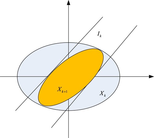
Finally, the detailed ellipsoidal method for the unknown state estimation, corresponding to UAV target tracking and recognition, is listed as follows, and its geometric form is seen in Figure .
| Step 1: | Collect the observed output data point | ||||
| Step 2: | Construct a strip that bounds the consistent state, i.e. information state set.
| ||||
| Step 3: | Set the initial ellipsoidal state set | ||||
| Step 4: | Calculate the first intersection | ||||
| Step 5: | Iteratively calculate the following intersection operations to get a sequence of ellipsoids, i.e. | ||||
Figure 3. Ellipsoidal method.
4. Synthesis analysis for ellipsoidal method
To give a synthesis analysis for our considered ellipsoidal method, that state space form (Equation2(2)
(2) ) is considered in this section again, i.e.
(18)
(18)
Noise
satisfying the following norm bound, i.e.
Ellipsoidal method is to build the ellipsoidal approximation of the state estimation recursively. Let
be the set of all states, where the system can be driven in instant
and assume that we build inner and outer ellipsoidal approximations
and
of the set
.
(19)
(19)
According to the problem of how to construct the inner and outer ellipsoidal approximations
and
, the reader can refer to our previous paper (Jianhong et al., Citation2020). This section gives some synthesis analysis about constructing the inner and outer ellipsoidal approximations.
First for convenience, the following Theorem 4.1 is given as follows.
Theorem 4.1
Let be nonsingular, and
be positive definite
matrices,
, then for every collection
of vectors from
, one has
(20)
(20)
Proof.
Construct the following symmetric matrix as
(21)
(21)
Applying Schur Complement Lemma on matrix C, then we have
(22)
(22)
Using the property about
, and the necessary and sufficient condition or the positive semidefinite, it is obvious that
(23)
(23)
where the assumptions
be nonsingular and
be positive definite matrices are used to guarantee that
(24)
(24)
Then applying Schur Complement Lemma on positive semidefinite matrix C again, it holds that
(25)
(25)
by the multiplication of the above inequality on the right by
and on the left by
, the following inequality is obtained:
(26)
(26)
substituting Equation (Equation26
(26)
(26) ) into inequality (Equation25
(25)
(25) ), which completes the proof of Theorem 4.1.
Based on Theorem 4.1, a parametric family of ellipsoids containing the arithmetic sum of m given ellipsoids are generated as other new alternative way. This new alternative form is formulated as the following Theorem 4.2.
Theorem 4.2
Given m full dimensional ellipsoids centred at the origin.
(27)
(27)
For every collection Λ of positive definite
matrices
such that
(28)
(28)
the ellipsoid
(29)
(29)
contains the sum
of the ellipsoids
.
Proof.
Set , then
(30)
(30)
where in above derivation process, the inequality from Theorem 4.1 is used.
Let us start with the observation that an ellipsoid contains
if and only if the following implication holds:
(31)
(31)
Then we choose
to guarantee
contains the sum
of the ellipsoids
, and every collection Λ of positive definite
matrices
such that
.
Which completes the proof of the Theorem 4.2.
After these parametric family of ellipsoids (Equation29(29)
(29) ) are obtained to contain the sum
of the ellipsoids
, then the smallest volume ellipsoid within this parametric family can be also reduced to one semidefinite program, which is seed as Theorem 4.3.
Theorem 4.3
To find the smallest volume ellipsoid in the family defined in Equation (Equation29
(29)
(29) ), it suffices to solve the following semidefinite program.
(32)
(32)
whose decision variables are
.
Proof.
For every collection Λ of positive definite matrices
such that
, and
.
Given m positive reals with unit sum, one defines the ellipsoid
This ellipsoid contains the arithmetic sum W of the ellipsoids
, and to approximate the smallest volume ellipsoid containing W. We only minimize
over λ varying in the standard simplex
.
Comment: As here this paper considered the case of bounded noise, the final result is to derive one ellipsoidal sequence, which include the accurate state estimation. Figure shows the ellipsoidal method, and the obtained ellipsoids are three-dimension shape. The always used method to measure the size of this three-dimension shape-ellipsoid is dependent of the volume. By the way, other specifications are used, for example, P-radius or robust radius. Due to the equivalent property among the volume, P-radius or robust radius, so we apply the volume to measure the size of the obtained ellipsoids.
The above Theorem 4.1–4.3 are three related results on outer ellipsoidal approximation, similarly the further result about inner ellipsoidal approximation is easily obtained as the following Theorem 4.4.
Theorem 4.4
Let be nonsingular
matrices,
, and let
be the associated ellipsoids in
. Let
, then
| (1) | Whenever | ||||
| (2) | Whenever A is such that
| ||||
Proof.
(1) As the associated ellipsoids
i.e.
Similarly the ellipsoid satisfies that
As
Similarly
and
where
is used in above mathematical derivation.
Then we have
which completes the proof.
The above new results give some improvements for our previous results, which will be applied in our latter research on multi-UAVs formation flight control.
(2) Represent the given centred at the original ellipsoids as
. Due to the fact that an ellipsoid
is contained in the sum
of the ellipsoids
if and only if one has
. Then we obtain that
. For the ellipsoid contained in the sum, we still have
(35)
(35)
Furthermore, we have
(36)
(36)
It means that
(37)
(37)
Rewriting Equation (Equation37
(37)
(37) ) as that
(38)
(38)
It equals to
(39)
(39)
Which completes the proof of the Theorem 4.4.
The above analysed results can not only be further alternative forms for outer ellipsoidal approximation and inner ellipsoidal approximation but also be used as the auxiliary steps for Section 3, where the number of ellipsoids is m = 2, so this further analysis process extends the results in Section 3.
5. Simulation
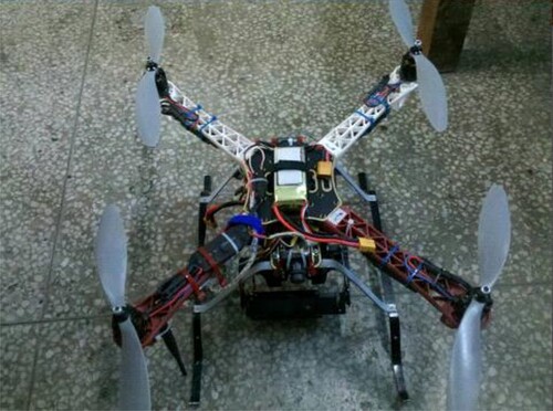
In this simulation example, a quadratic UAV is used, as it can take off and land vertically. It has strong air control capability, good static flight and low speed flight characteristics, which is shown in Figure to achieve various of flight attitudes. This quadratic UAV adopts the basic axis-symmetric layout, the four crisscrossed robots are evenly distributed, and the structure is simple. Furthermore, the quadratic UAV is mainly composed of rotor, body, flight control equipment, motor, power supply and landing gear, etc. The quadrotor UAV has four controllable basic motion states during flight, namely vertical flight, longitudinal flight, lateral flight and horizontal rotation. Its four flight module is plotted in Figure , whose vertical flight is the easiest to control among the four states. At the same time, the output power of the four motors is increased, so that the rotor speed increases and the total pulling force increases. When the total pulling force is greater than the gravity, the quadrotor flies vertically upward. The output power of the small four motors slows down the rotor speed, reduces the total pulling force, and the quadrotor flies vertically downward.
Figure 4. UAV model.
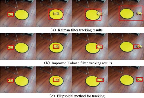
To compare the tracking results of applying our proposed ellipsoidal method and classical Kalman filter, we let the quadratic UAV track one moving car, whose average velocity of set to be 0.2–5 m/s. Figure shows the image sequences for three methods, i.e. classical Kalman filter, improved Kalman filter and ellipsoidal method, then only frames (1, 30, 46, 53) are extracted from the first image sequence. In this image sequence, there is a large yellow circle with a colour very similar to the four-wheel drive car as a background noise, and the car starts to move slowly and almost uniformly, and suddenly accelerates at frame 52. After observing Figure for the above Kalman filter, when at the 17th frame, the car enters near the centre of the yellow circle. Due to the interference of similar colours, the target cannot be tracked correctly. The tracking window is enlarged to include the entire yellow circle. In the 46th frame, part of the car leaves the yellow circle, and the tracking window continues to enlarge. But for the tracking results from our ellipsoidal method, through image matching, the tracking target is firstly identified and the window position and size are automatically determined. Ellipsoidal method combines the advantages of the two methods to enhance the real-time and robustness of tracking. No matter the target object is disturbed by similar colours or the speed is suddenly accelerated, that quadratic UAV can track the target very accurately and effectively.
Figure 5. Four flight modules.
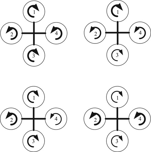
Figure 6. Comparisons with Kalman filter method.
6. Conclusion
In this paper, ellipsoidal method is proposed in UAV target tracking and recognition, and its synthesis analysis is also given too. The problem about why the ellipsoidal method is applied is that the noise, existing in the nonlinear system or linear system, is unknown but bounded, i.e. its probabilistic density function of the considered noise is unknown, so the classical Kalman filter can not work well. Within the synthesis analysis for the ellipsoidal method, the intersection operation between an ellipsoid and a strip is represented as another ellipsoid. Through the generated ellipsoid sequences, the centre of the final ellipsoid is chosen as the nice state estimation. Then other applications of our considered ellipsoidal method is the interesting direction of future work.
Disclosure statement
The authors declare that there is no conflict of interests regarding the publication of this paper.
Data availability
The data used to support the findings of this study are available from the corresponding author upon request.
Additional information
Funding
References
- Bravo, J. M., Alamo, T., & Vasallo, M. (2007). A general framework for predictions based on bounding techniques and local approximations. IEEE Transactions on Automatic Control, 62(7), 3430–3435. https://doi.org/10.1109/TAC.2016.2612538
- Campi, M. C., Care, A., & Garatti, S. (2021). The scenario approach: A tool at the service of data driven decision making. Annual Reviews in Control, 52(2), 1–17. https://doi.org/10.1016/j.arcontrol.2021.10.004
- Care, A., Campi, M. C., & Csayi, B. C. (2021). Facing undermodelling in sign perturbed sums system identification. Systems Control Letters, 153(7), Article 104936. https://doi.org/10.1016/j.sysconle.2021.104936
- Care, A., Csorji, B., & Campi, M. C. (2018). FInite sample system identification: an overview and a new correlation method. IEEE Control Systrems Letters, 2(1), 61–66. https://doi.org/10.1109/LCSYS.2017.2720969
- De Peris, C., & Tesi, P. (2020). Formulas for data driven control: stabilization optimality and robustness. IEEE Transactions on Automatic Control, 65(3), 909–924. https://doi.org/10.1109/TAC.9
- Jianhong, W., He, M., & Ramirez-Mendoza, R. A. (2020). Application of ellipsoidal approximation into target tracking for multi UAVs formation cooperation detection. International Journal of Modelling, Identification and Control, 35(2), 108–119. https://doi.org/10.1504/IJMIC.2020.113712
- Jianhong, W., Ramirez-Mendoza, R. A., & Xiaojun, T. (2021). Target tracking algorithm for multi UAVs formation cooperation detection. Systems Science Control Engineering, 9(1), 417–429. https://doi.org/10.1080/21642583.2021.1916789
- Khoresani, M. M., & Wayer, E. (2020). Non-asymptotic confidences regions for the parameters of EIV systems. Automatica, 115(5), Article 108873. https://doi.org/10.1016/j.automatica.2020.108873
- Xiaojing, Z., Grammatico, S., & Schildback, G. (2015). On the sample size of random convex programs with structural dependences on the uncertainty. Automatica, 60(10), 182–188. https://doi.org/10.1016/j.automatica.2015.07.013
- Xiaojing, Z., Kamgarpour, M., & Georghial, A. (2017). Robust optimal control with adjustable uncertailty sets. Automatica, 75(1), 249–259. https://doi.org/10.1016/j.automatica.2016.09.016