
 ?Mathematical formulae have been encoded as MathML and are displayed in this HTML version using MathJax in order to improve their display. Uncheck the box to turn MathJax off. This feature requires Javascript. Click on a formula to zoom.
Abstract
This paper proposes a Nash bargaining cooperative game model for a microgrid cluster system with double re-energy-load delay considering electricity, heat and gas multi-energy synergies. With the minimization of the operating cost of each microgrid as the objective function, a low-carbon operation model of a multi-energy complementary integrated energy microgrid considering fuzzy opportunity constraints is developed, an optimal operation mechanism including carbon quota and carbon trading is assessed, and a carbon capture system and an electricity-gas conversion device are added to the improved cogeneration unit model. Source-load uncertainty in microgrids is described in terms of new fuzzy parameters of new energy and undefined parameters of load demand. Each microgrid plays a second game with the marginal contribution rate and carbon trading cost rate as the bargaining power. The model is solved in a distributed manner using the ADMM-RGE algorithm. Finally, the simulation results show that the proposed multi-microgrid power-sharing way maximizes the benefits of microgrid alliances; the cooperative help of microgrid alliances is pretty distributed according to the size of each microgrid's energy contribution; carbon capture joint power-gas systems and energy sharing methods between microgrids can effectively reduce carbon emissions during microgrid operation.
1. Introduction
With the rapid development of the economy, energy consumption continues to grow, carbon emissions are increasing daily, and environmental pollution and climate change problems are becoming increasingly severe (Alaboudy et al., Citation2012). For this reason, China has committed to achieving the goal of carbon peaking and carbon neutrality by 2030 and developing carbon trading and other related policies. The integrated energy system is based on traditional electric energy. It adds other energy supply methods such as natural gas, heat and cold, which effectively improves the efficiency of the energy supply, empowers the concept of low carbon and better realizes the consumption of renewable energy (Ambia et al., Citation2021).
Research on energy trading among distributed microgrids mainly includes (1) promoting rated commercial energy trading among producers and consumers through blockchain technology (Astriani et al., Citation2018) and (2) maximizing the revenue of electricity trading among microgrids using game theory methods. Energy trading between multiple entities can generally be done in cooperative and non-cooperative games (Basak et al., Citation2012).
In the first category, the energy surplus or deficiency of the producer-consumer is always into two classes of opposing buyers and sellers, often through the Stackelberg game to optimize their respective individual costs to compete with each. They often compete to achieve the minimum energy cost based on Nash equilibrium through the Stackelberg game to optimize their costs (Che et al., Citation2015). The literature (Che & Chen, Citation2012) divides multiple community microgrids into buyer and seller. Mutual master-slave competition. Another method based on a bidding auction game (Dawoud et al., Citation2017; Pang et al., Citation2022) has the advantage that it is easy to write intelligently. The advantage of this approach is that it is easy to write intelligent contracts. In a non-cooperative game, each subject is considered selfish. In a non-cooperative game, each issue is considered selfish and antagonistic and thus lacks consideration of the overall interest.
In the second category, multi-subject P2P energy transactions are modelled as the coalition alliance game model or Nash bargaining (NB) model. Model. In the literature (Debouza et al., Citation2022), based on the coalition game optimization approach, the mutual benefits are distributed among the coalition members based on the Shapley value. The coalition game model is computationally complex and can only ensure the maximization of uses within a stable coalition and maximize benefits within the stable alliance but not the global benefits (Debouza et al., Citation2022). In this regard, the Nashnegotiation model overcomes the limitations of coalition games (Dawoud et al., Citation2017; Pang et al., Citation2022). In this paper, the optimization method belongs to the research area of Nash negotiation.
The main work of this paper differs from the existing work as follows: In terms of modelling, unlike the conventional combined heat and power (CHP) model, this paper considers the low-carbon operation requirements and constructs a new CHP unit model that couples a carbon capture system (CCS) with a power to gas (P2G) unit. This paper develops a new CHP unit model that connects a carbon capture system (CCS) and a power-to-gas (P2G) unit into a CHP unit. In terms of optimization methods, we first propose a multi-microgrid energy-sharing architecture based on microgrid cluster power trading considering source-load uncertainty and apply Nash negotiation theory to construct a multi-microgrid power-sharing cooperative optimization model, and then divide it into two stages: Stage 1: minimum coalition operation cost and Stage 2: maximum microgrid cluster revenue distribution, to investigate the impact of source-load uncertainty on microgrid operation cost. Finally, the proposed model is solved using the ADMM-RGE algorithm in the solution algorithm. The simulation results verify that the proposed optimal scheduling strategy not only reduces the operating cost of each microgrid but also does not require too much information interaction between microgrids during the calculation. In addition, the impact of confidence level on the operating cost and carbon emission of microgrid clusters is also investigated.
2. Integrated energy microgrid cluster structure and mathematical model
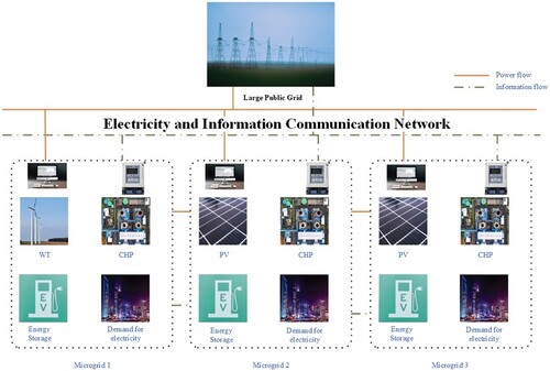
The architecture of a microgrid cluster system consisting of three microgrids connected to the public grid is shown in Figure . Each microgrid in the system is mainly composed of wind turbines, PV turbines, micro gas turbines, CHP units with CCS and P2G technologies, batteries, and electric heating loads. Multiple MGs have different and complementary energy production and sales. A 2-step priority consumption and dispatch strategy for new energy is implemented to achieve efficient consumption of new energy in microgrid clusters. (1) to minimize the operating cost of each microgrid to meet the electricity and heat demand of users within the microgrid; (2) to solve the revenue distribution problem after trading within the microgrid cluster. The energy trading market described in this paper consists of a sizeable public grid, a microgrid cluster trading centre and each microgrid. In the microgrid cluster power trading, microgrids can interact with the large public grid for power and participate in energy trading among microgrids. When the net force in the microgrid is greater than 0, the microgrid needs to purchase power from the public grid or the rest of the microgrid, which is a power-purchasing microgrid; when the net force in the microgrid is less than 0, the microgrid needs to sell power to the public grid or other microgrids, which is a powerful selling microgrid; when the net force in the microgrid is equal to 0, the microgrid does not need to participate in energy trading, which is a balancing microgrid. The microgrid is a balance microgrid at this time.
Figure 1. Microgrid cluster architecture.
3. Integrated energy microgrid foundation model
This paper studies an integrated energy microgrid with complementary electricity, heat and gas. To reduce the carbon emissions generated by the operation of CHP units, this paper proposes to integrate carbon capture and P2G technologies into the CHP unit model to operate synergistically as a whole in response to the national development strategy of green and low-carbon energy transformation.
3.1. System model
Gas unit model
The kth (k = 1, 2, 3) microgrid whose gas units burn natural gas to produce electricity has the following relationship between power generation and natural gas consumption.
(1)
(1) where
is the natural gas consumption;
is the generation efficiency of the gas-fired unit;
is the calorific value of natural gas combustion; considering that the cogeneration power of the gas-fired unit has the constraint of ‘heat for electricity’, the thermal capacity of the gas unit at time T can be described by Equation (2).
(2)
(2) where
is the heating power of the CHP unit at time t; and
are the electrical and thermal conversion coefficients of the HP unit corresponding to the minimum and maximum output power, respectively;
is the linear supply slope of the electrical energy produced by the CHP unit;
and is the thermal power corresponding to the minimum power generated by the CHP unit.
The heat production power of the gas boiler is.
(3)
(3) where
is the natural gas consumption of the gas boiler in the kth microgrid in period t;
is the efficiency of the gas boiler.
CHP model with CCS and P2G technology
In the CHP model with P2G and CCS technologies, the CHP generates power as.
(4)
(4) where
does the CHP unit demand the electricity to supply electricity;
is the conversion factor of the electricity consumed to capture CO2;
is the amount of CO2 produced per unit of electricity produced by the CHP unit;
Is the electricity consumed to supply P2G.
P2G power consumption of electrical energy to produce natural gas.
(5)
(5) The electrical power of CCS, P2G and CHP are all within their corresponding upper and lower power limits, respectively.
(6)
(6) where
and
are the lower and upper limits of CCS power consumption;
and
are the lower and upper limits of P2G power consumption;
and
are the lower and upper limits of CHP power generation, respectively.
Electrothermal coupling characteristics power with P2G and CCS and CHP systems:
(7)
(7) Bringing the upper and lower bound constraints of Equation (6) into Equation (7), the coupling characteristics of the new CHP electrothermal power with P2G and CCS are obtained as follows.
(8)
(8)
The coupling relationship between the power supply, thermal power and gas production power of CHP is obtained as shown in Equation (9).
(9)
(9)
Battery Energy storage system model
The charge state of the battery storage system at time t during the charging and discharging process is shown in Equation 10.
(10)
(10) where energy loss coefficient
≈ 0; charging and discharging efficiency
< 1<
;
Electrical and thermal load model
The electrical load in the microgrid at the time consists of three parts: fixed load
and level able electrical load
, and curtailable electrical load
, which can be expressed as:
(11)
(11)
(12)
(12)
(13)
(13)
The actual thermal load in the microgrid is divided into two parts: fixed thermal load
and reduced thermal load
.
(14)
(14) The reduced thermal load
can meet the following constraints.
(15)
(15) where
indicates the upper limit of the heat load that can be reduced.
Carbon emission model
The CO2 emissions from the microgrid are expressed as.
(16)
(16) where a, b and c are the CO2 emission factors of the CHP unit and gas boiler, respectively,
is the reduction of system CO2 emission after the addition of CCS and P2G.
3.2. Cost model
Based on the microgrid system model established in Section 3.1, a cost optimization model for the cooperative sharing of electricity from multiple microgrids was developed.
(17)
(17) where
is the overall operating cost of the kth microgrid participating in inter-microgrid power trading.
The operating costs of CHP units with CCS and P2G technologies are
(18)
External interaction costs
Microgrid external interaction costs include the purchase cost of natural gas and the purchase and sale cost of electricity interacting with the grid.
(19)
(19) where
is the unit price per unit of natural gas purchased;
is the amount of gas purchased when the CHP system is in operation; and
is the unit price of electricity bought and sold, respectively.
Energy storage system operating costs
The operating cost of ESS is.
(20)
(20) where
is the cost factor of energy storage system operation.
Carbon quota and carbon trading costs
The carbon quota for microgrids is.
(21)
(21) where
is the carbon emission allowance per unit of electricity produced by the CHP microgrid;
is the new energy generation power.
Cost of carbon trading Derived as follows.
(22)
(22) where
is the carbon trading cost factor.
Demand response costs
Transferring or disconnecting the load requires compensation from the customer.
(23)
(23) where
is the demand response cost;
,
,
and are the compensation costs for load shifting and load shedding, respectively.
Electricity transmission cost
The transmission of electricity between microgrids requires the payment of a cross-grid fee to the distribution network operator, and the cost of the cross-grid price is.
(24)
(24) where
is the cost per unit of electrical energy over the grid.
Electricity sharing costs
Let denote the amount of electric energy traded between microgrid i and other microgrid j at time t. If
> 0, microgrid I obtain electric power from microgrid j, and vice versa, it supplies electric energy to microgrid j. Let
denote the price of electric energy that the microgrid I need to pay for the interacted electricity
, and the electric energy sharing cost
is:
(25)
(25)
3.3. Consider source-load fuzzy chance constraint power balance constraint
Usually, the new energy generating unit output and load demand are described as deterministic values; however, the fluctuating and intermittent nature of the new energy unit output and the uncertainty of the load demand will have an impact on the microgrid operation, therefore, for the effects of the microgrid scenery output and load uncertainty, this chapter constructs a microgrid robust optimization operation model with strict power balance constraints as.
where is the forecast value of renewable units at moment T;
is the forecast error of wind turbines or PV units at moment T;
is the amount of abandoned wind or light in the day-ahead dispatch plan at moment T;
is the forecast value of the electric load at moment T;
is the forecast error of electric load at the moment T.
Since the system power balance contains uncertain variables, the power balance under deterministic conditions will no longer be applicable; therefore, the influence of system uncertainty factors should be considered in inter-microgrid power trading. In this paper, a fuzzy processing method is used to introduce wind power undefined parameters and load fuzzy parameters to relax Equation (29) into a power constraint balance under a specific confidence level condition so that the possibility of this balance constraint is not less than the power constraint balance under. The chance of this balance constraint holding is not less than, so the set of uncertainties is constructed as follows.
(26)
(26)
(27)
(27) where
indicates the credibility of the event.
In this paper, in solving the microgrid day-ahead dispatching model with fuzzy opportunity constraint planning, the conversion method is used to transform the fuzzy opportunity constraint planning problem into a deterministic constraint planning problem. In the microgrid system operation with high-security requirements, the confidence level is therefore not easily too low, and when >1/2, the apparent equivalence
of the opportunity constraint is.
(28)
(28) where
,
is the assumed two functions;
is a part of the function
, which can be referred to in the literature (18);
-
(k = 1,2 … .t) is the affiliation parameter.
The expression of the trapezoidal fuzzy parameter is.
(29)
(29) where is
the fuzzy parameter in the system;
is the predicted value;
,
,
and
is the affiliation parameter of wind power and load in time T;
,
,
and
is the proportional parameter, which is generally determined by the historical data of the fuzzy parameter.
Equation (29) is transformed into the corresponding precise equivalence class according to the transformation method of trapezoidal parameters. The particular equivalence class under triangular fuzzy parameters is used in this paper.
The power balance precise equivalence class is.
(30)
(30) where
is the affiliation parameter of wind power;
is the affiliation parameter of electric load.
3.4. Other constraints
Thermal power balance constraint
Gas balance constraint
The addition of P2G can reduce the need for gas purchases.
Constraints on power trading within microgrid clusters
Within the power transmission limits of the electrical energy transmission line between microgrids at each period t output or received.
(33)
(33) Let
denote the total amount of electricity traded by microgrid I participating in energy sharing in time t and the corresponding payment to be paid
. The microgrid participating in power trading must satisfy the energy sharing balance and transaction payment balance constraints.
(34)
(34)
(35)
(35)
4. Microgrid cluster power sharing mechanism based on asymmetric Nash negotiation game
4.1. ADMM-RGS algorithm
ADMM can decompose a complex problem into multiple sub-problems and is suitable for solving multi-subject optimization problems. The model proposed in this paper, the standard ADMM with two operators, is not applicable and needs to be extended to the three-operator form. Still, the extended form cannot ensure the convergence of the solution results. Therefore, it is necessary to add the correction link of variables, i.e. ADMM-RGS, to the 3-operator basis to ensure the algorithm's convergence. The direct extension form of the 3-operator ADMM can be expressed as.
(36)
(36)
(37)
(37)
(38)
(38) where
,
and
are the three operators; A, B, C and d are the coupling coefficient matrices; x, y and z are the coupling variables of the three subproblems;
is the augmented Lagrangian function;
is the Lagrangian multiplier;
is the penalty factor.
4.2. Stage 1: minimizing microgrid operating costs
First, it is necessary to establish a microgrid cluster operation cost minimization model, where the total cost is the sum of the energy cost of each microgrid, and construct the power trading model of the microgrid cluster based on the Nash game model as follows.
(39)
(39) Since the microgrid cluster power trading balance constraint is multi-coupled among all microgrids, the auxiliary variables are introduced to transform the microgrid cluster operating cost minimization model into a dual-coupling model as shown in Equation (41) to equate the multi-coupling constraint.
(40)
(40) where
denotes the electricity I plan to trade with microgrid j; then
denotes the electricity that microgrid j intends to change with microgrid I; when
it indicates that the electricity transaction between microgrid i and microgrid j is completed. The steps for solving the microgrid cluster operation cost minimization model based on the ADMM-RGE algorithm are as follows.
Step 1: Establish the incremental Lagrangian function for minimizing the cost of microgrid cluster operation.
(41)
(41) where
is the Lagrangian multiplier; set penalty parameter
= 10−3.
Step 2: To ensure an orderly microgrid cluster market, only electricity information is exchanged between microgrids and the microgrid trading strategy is updated by local calculation. Let u denote the number of iterations. In each iteration, the following steps are executed.
The update strategy for Microgrid i is as follows.
(42)
(42) The update strategy for microgrid j
is as follows.
(43)
(43)
Until each microgrid updates its trading power strategy in the current iteration.
Step 3: After one round of iterations, the formula updates the Lagrange multiplier.
(44)
(44) Step 4: update the number of iterations u = u + 1.
Step 5: Determine whether the algorithm converges.
(45)
(45) where
is the electric power residual value of the mth microgrid;
for convergence accuracy, this paper takes 10-3.
4.3. Stage 2: cost allocation within the microgrid cluster
This paper uses marginal contribution rate and carbon transaction cost to quantify the weights of different microgrids in the internal trading of micro electricity clusters. Then, the microgrids negotiate with each subject's electric energy contribution among themselves twice to determine the internal trading tariff between each subject. The process of revenue allocation after internal trading is as follows.
Firstly, the contribution of each microgrid to the cooperation is reflected by comparing the cost changes before and after joining the collaboration in the process of power trading. The marginal contribution rate is given by.
(46)
(46) where
is the cost of each microgrid before cooperation,
is the cost of each microgrid before cooperation, i.e.
The carbon cost ratio is
(47)
(47) where
denotes the carbon cost of each microgrid;
indicates the operating cost of each microgrid.
The marginal contribution rate and the carbon trading cost ratio
yield a total bargaining value
of.
(48)
(48) where
and
are the marginal contribution rate
and the carbon cost ratio
, respectively, as weights in the bargaining power
.
Finally, normalizing the above equation, the bargaining factor for each microgrid is.
(49)
(49) Finally, according to the established quantitative model of bargaining power, the microgrid cluster optimal interaction power is substituted into the microgrid cluster revenue allocation model, which is constructed based on the model of Nash negotiation as shown in Equation (51).
(50)
(50)
The microgrid cluster internal transaction allocation model is similar to the microgrid cluster operation cost minimization model solving process, which is not repeated in this paper.
5. Case simulation analysis
5.1. Basic data
The power-sharing mechanism among the three microgrids is studied in the asymmetric Nash negotiation-based microgrid cluster power-sharing model constructed in this paper (Table ). Microgrids a and c are conventional CHP units. At the same time, Microgrid b is modified into a new CHP unit model with a carbon capture system and electric-to-gas converter to verify its effectiveness in carbon reduction. The unit output and electric and thermal load forecast data of each microgrid are shown in Figure . The interactive electricity price between each microgrid and the public main network is shown in Table .
Figure 2. (a) MGa Forecast values of pre-day electrical load, thermal load and wind turbine output. (b) MGb day-ahead electric load, thermal load and wind turbine output forecast. (c) MGc day-ahead electric load, thermal load and wind turbine output forecast.
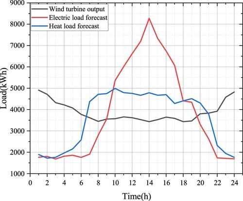
Figure 2b. Continued.
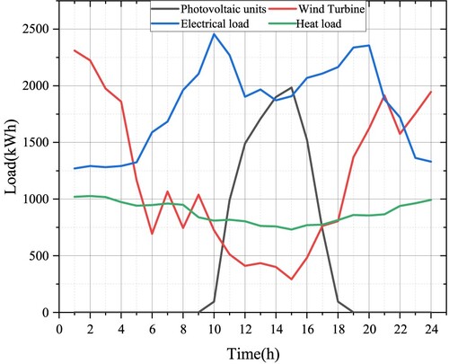
Figure 2c. Continued.
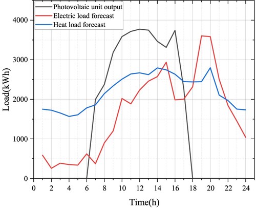
Table 1. Parameters of integrated energy microgrid dispatching model.
Table 2. Electricity purchasing price and selling price of Microgrid.
5.2. Analysis of algorithm convergence
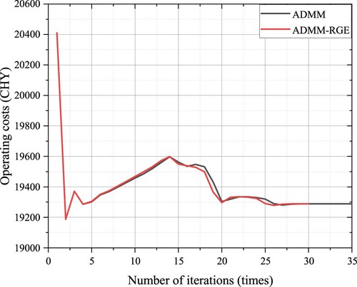
In this chapter, The ADMM-RGE algorithm is used to solve the distributed problem. Figure shows the convergence result of micro-grid cluster operation cost considering the uncertainty of source load. The ADMM algorithm converges to 19288.26 CHY after 35 iterations, and the calculation time is 203 s, while the ADMM-RGE algorithm only needs 30 iterations and takes 167 s. Therefore, the algorithm adopted in this chapter has good convergence and computational speed.
Figure 3. Microgrid cluster total operating cost convergence curve.
5.3. Analysis of power-sharing results of microgrid cluster
Figure shows the power-sharing results of microgrid clusters with source load uncertainties taken into account. As can be seen from Figure , during the period of 06:00–18:00, the photovoltaic power generation of MGc is in excess, and the energy demand of MGb is large. MGc supplies energy to MGb to reduce the operation cost of the microgrid cluster. During 00:00–06:00 and 18:00–24:00, due to natural factors, the MGc photovoltaic generating set can hardly supply power. In this case, power needs to be purchased from MGa and MGb to meet the needs of users in the microgrid. To reduce the risk caused by the uncertainty of source load, the MGb needs to ensure sufficient standby scheduling capacity, which is in the situation of ‘supply is less than demand’ in the whole period. During 00:00–08:00 and 18:00–24:00, the wind power unit has excess capacity and supplies energy to other microgrids. During 08:00–18:00, the wind power unit has insufficient capacity and needs to purchase power from MGc to meet its demand.
Figure 4. Electricity trading results of each subject in the microgrid cluster.
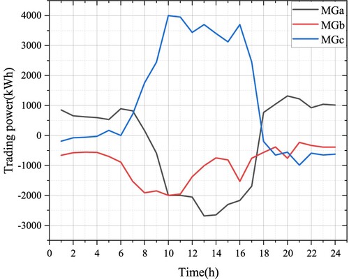
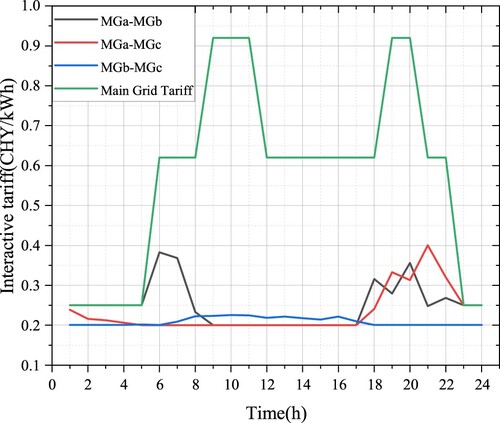
Figure shows the transaction price result of each microgrid subject after mutual negotiation in the microgrid cluster. As shown in Figure , the internal transaction price of the micro-grid cluster is between the electricity selling price and the electricity purchasing price of the superior main network. Therefore, the electric energy trading of the micro-grid cluster can sell the electric energy at a price higher than the electricity purchasing price of the main network, and purchase the renewable energy electricity at a price lower than the electricity selling price of the main network, thus effectively reducing the operation cost of each main body of the micro-grid cluster.
Figure 5. Electricity trading tariff results within the microgrid cluster.
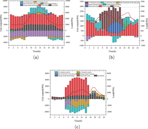
The power optimization of each main body of the microgrid cluster is shown in Figure . It can be seen that each main body of the microgrid cluster preferentially consumes renewable energy on the premise of realizing the optimization of its power scheduling. For the shortage or surplus power, the cost optimization of the microgrid cluster can be realized using power-sharing of the microgrid cluster. For CHP units in MGb, almost no power is output to the demand side, but all the power is used for P2G and CCS equipment, which improves the operating income of the microgrid and reduces the carbon emission of the system.
Figure 6. Power balance results for each subject within the microgrid cluster. (a) MGa; (b) MGb; (c) MGc.
5.4. Carbon emission analysis of microgrid cluster
Table shows the carbon emission before and after power transactions of various comprehensive energy microgrids, taking source load uncertainty into account. As can be seen from Table , the carbon emissions of each microgrid after participating in the internal transaction of the microgrid cluster are reduced by 327.38, 862.59 and 267.03 kg, respectively. It can be seen that after participating in the internal transaction of the microgrid cluster, each microgrid reduces the carbon emission of the microgrid cluster by giving priority to the use of clean energy such as landscape.
Table 3. Carbon emissions before and after microgrid cluster sharing with source-load uncertainty.
5.5. Analysis of benefits and costs of microgrid sets
Table shows the operating cost results before and after microgrid cluster sharing, taking source load uncertainty into account. Table shows that the negotiation coefficients of each microgrid are 1.17, 0.85 and 1.23 respectively, and the cost of each microgrid is reduced by −100.31, 3578.25 and −3481.95 CHY. It can be seen that the benefit distribution method based on negotiation power proposed in this paper can reduce the operating cost of each main body of the microgrid cluster (Table ).
Table 4. Benefit and cost studies before and after microgrid cluster sharing under source-load uncertainty.
Table 5. Comparison of benefit distribution of standard Nash models.
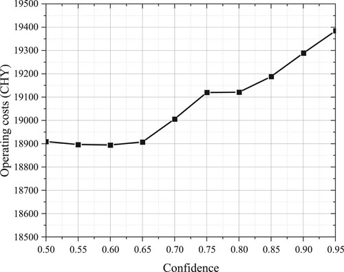
The operating costs of microgrid clusters under different confidence levels are shown in Figure As can be seen from Figure , with the improvement of confidence, the operating cost of microgrid clusters is constantly increasing. This is because to reduce the operation risk caused by the uncertainty of source load, the system needs to increase the reserve capacity, which leads to a decrease in system benefits. In the actual operation of the microgrid, the appropriate confidence level should be selected according to the actual demand of the microgrid cluster, considering the security and economy comprehensively.
Figure 7. Relationship between confidence and operating costs.
6. Conclusion
With the increasing proportion of renewable energy supply in the power system, a multi-microgrid inter-energy trading model based on a cooperative game framework is proposed in this paper in response to the requirement for low-carbon operation of the power system. The main findings are as follows.
Based on the optimization model of multi-microgrid power-sharing solved by the ADMM-RGE algorithm, each microgrid only exchanges a limited amount of transacted power and transacted tariff information during the cooperation process. Thus the privacy of each participating subject can be effectively protected, and the proposed algorithm has good convergence.
Compared with independently operated microgrids, the operating cost of each microgrid is effectively reduced, and the local consumption rate of new energy can be significantly improved.
Microgrid quantifies bargaining power according to marginal contribution rate and carbon cost rate in the microgrid cluster. Electric energy trading takes bargaining power as an essential indicator of revenue distribution and achieves fair revenue distribution. Each microgrid gets more benefits in the distribution by improving bargaining power, thus effectively stimulating each microgrid to participate in energy cooperation and motivating distributed subjects to increase new energy generation construction.
Improving CHP units by adding carbon capture electrical co-conversion systems and sharing power among microgrids can reduce carbon emissions during microgrid operation and promote low-carbon processes. In future research, we will further study the low-carbon process in the context of carbon trading and review the advanced modelling and capacity optimization allocation of carbon capture systems and electrical co-conversion units in microgrids to minimize carbon emissions in cogeneration-type microgrid operation.
Disclosure statement
No potential conflict of interest was reported by the author(s).
References
- Alaboudy, A. H. K., Zeineldin, H. H., & Kirtley, J. L. Jr (2012). Microgrid stability characterization after fault-triggered islanding incidents. Ieee Transactions on Power Delivery, 27(2), 658–669. https://doi.org/10.1109/toward.2012.2183150
- Ambia, M. N., Meng, K., Xiao, W., & Dong, Z. Y. (2021). Nested formation approach for networked microgrid self-healing in islanded mode. Ieee Transactions on Power Delivery, 36(1), 452–464. https://doi.org/10.1109/toward.2020.2977769
- Astriani, Y., Shafiullah, G. M., Anda, M., & Hilal, H. (2018). Techno-economic Evaluation of Utilizing a Small-Scale Microgrid (F. E. C. E. Appl Energy Innovation Inst; Malardalen Univ, C. J. P. Solar Energy Soc Hong Kong & U. Energy Syst, Trans.) 10th International Conference on Applied Energy (ICAE) (Vol. 158, pp. 3131–3137). Hong Kong, Hong Kong.
- Basak, P., Chowdhury, S., Dey, S. H. N., & Chowdhury, S. P. (2012). A literature review on integration of distributed energy resources from the perspective of control, protection, and stability of microgrid. Renewable & Sustainable Energy Reviews, 16(8), 5545–5556. https://doi.org/10.1016/j.rser.2012.05.043
- Che, L., Shahidehpour, M., Alabdulwahab, A., & Al-Turki, Y. (2015). Hierarchical coordination of a community microgrid With AC and DC microgrids. Ieee Transactions on Smart Grid, 6(6), 3042–3051. https://doi.org/10.1109/tsg.2015.2398853
- Che, Y., & Chen, J. (2012). Research on design and control of microgrid system. Przeglad Elektrotechniczny, 88(5B), 83–86.
- Dawoud, S. M., Lin, X., & Okba, M. I. (2017). Optimal placement of different types of RDGs based on the maximization of microgrid loadability. Journal of Cleaner Production, 168, 63–73. https://doi.org/10.1016/j.jclepro.2017.08.003
- Debouza, M., Al-Durra, A., El-Fouly, T. H. M., & Zeineldin, H. (2022). Establishing and operating experiential benchmark setups of dc microgrids: A guideline. Ieee Industry Applications Magazine, 28(5), 16–31. https://doi.org/10.1109/mias.2022.3160980
- Pang, K., Zhou, J., Tsianikas, S., & Ma, Y. (2022, Special Issue). Deep reinforcement learning for resilient microgrid expansion planning with multiple energy resources. Quality and Reliability Engineering International. https://doi.org/10.1002/qre.3203