
ABSTRACT
We use analytical aberration-corrected high-resolution scanning transmission electron microscopy to image the atomic structure of the layered ternary transition metal (M) borides, Cr2AlB2, Fe2AlB2, and MoAlB. In these ternaries, MB layers and Al single or double atomic layers are interleaved. The atomic positions of the M elements and Al are clearly resolved by Z-contrast images. The following structural defects are also found and described herein: a 90° twist boundary along [010] in Cr2AlB2, a tilt boundary in Fe2AlB2, and Mo2AlB2-like stacking faults in MoAlB, where some of the MB-based structures are intercalated by one (instead of two) Al layer(s).
GRAPHICAL ABSTRACT
IMPACT STATEMENT
Atomic structures of ternary transition metal borides Cr2AlB2, Fe2AlB2, and MoAlB are observed for the first time by HRSTEM. Some structural defects are also found in those borides.
Transition metal borides are among the hardest and highest melting point compounds known [Citation1] and are therefore used as wear resistant coatings [Citation2–4]. They are also used in permanent magnets [Citation5], primary battery electrodes [Citation6,Citation7], and high-temperature structural applications [Citation8,Citation9]. For high-temperature applications in air, however, the binary transition metal borides are limited because of their well-established poor oxidation resistance [Citation10,Citation11]. Quite recently, we reported on a ternary Al-containing boride—MoAlB—that forms a quite protective and adherent alumina layer when heated in air at temperatures up to 1400°C. In that respect, this compound behaves like some of the Mn+1AXn, or MAX, phases in which M is early transition metal, A is a Group IIIA–IVA element, and X is C or N and n = 1, 2, or 3. The MAX phases (space group of P63/mmc) are composed of a ‘Mn+1Xn’ sublattice interleaved with monolayers of the ‘A’ element, like Al [Citation12]. It is fairly well established at this time that some Al-containing MAX phases, notably Ti2AlC, are quite oxidation-resistant because Al diffuses out of the structure and forms a dense protective surface aluminum oxide layer [Citation13–15].
Our recent work was spurred by the work of Ade and Hillebrecht, who synthesized single crystals of many previously reported MAlB (M = Mo, W) and M2AlB2 (M = Cr, Mn, Fe) compounds, and discussed their structural relationship to other transition metal borides and their similarity to the MAX phases [Citation16]. Isostructural M-site solid solutions, namely (Mox, Me1−x)AlB, where Me = Cr, W and (Fex, Me2−x)AlB2, where Me = Cr, Mn, have also been reported [Citation17,Citation18]. These ternary borides crystallize in a number of structures including Cr3AlB4 and Cr4AlB6, but the most common ones are of the M2AlB2-type [Citation19,Citation20] and the MAlB-type [Citation21–23]. In this work, we focus on the latter two. In the M2AlB2 structure—space group Cmmm—the transition metal boride sublattice is interleaved by one Al layer (Figure (a)). In the MAlB structure—space group Cmcm—two Al layers interleave the MB sublattice, as shown in Figure (b). These crystal structures were determined by means of X-ray diffraction (XRD).
Figure 1. Atomic models of (a) M2AlB2, (b) MAlB in [100] and [001] zone axes. (c) Schematic of A-HRSTEM instrument together with an example of EDX mapping performed on Mo2Ga2C [Citation24].
![Figure 1. Atomic models of (a) M2AlB2, (b) MAlB in [100] and [001] zone axes. (c) Schematic of A-HRSTEM instrument together with an example of EDX mapping performed on Mo2Ga2C [Citation24].](/cms/asset/9a9ee972-f19b-4dd5-917a-274a3c188d98/tmrl_a_1245682_f0001_c.jpg)
High-resolution scanning transmission electron microscopy (HRSTEM) is an effective intuitive technique for structural characterization of such complex nanolaminated transition metal borides. By using high-angle annular dark-field detector, heavy elements such as Mo scatter electrons at high angles and appear as bright regions, whereas less heavy elements (e.g. Al) scatter less electrons and thus appear as gray, or even out of contrast. To see light elements, such as B, an annular bright field (ABF) detector can be utilized, which collects electrons scattered at low scattering angles by the light elements. Thus, Z-contrast scanning transmission electron microscopy (STEM) images not only indicate the atomic arrangements, but also carry chemical information [Citation25]. In case of elements with close atomic numbers displaying similar contrast in the Z-contrast image (e.g. Ti and Cr), energy-dispersive X-ray (EDX) or electron energy loss spectroscopy (EELS) can be simultaneously performed with different detectors and all information is correlated. Thus, EDX and EELS mappings at the atomic level can be achieved, which provide composition information at atomic spatial resolution and consequently atomic arrangements [Citation26]. Figure (c) is a schematic diagram of A-HRSTEM instrument together with an example of Mo2Ga2C imaged by EDX spectroscopy mapping. This figure shows how those techniques work in an analytical high-resolution scanning transmission electron microscopy (A-HRSTEM) instrument. Except for our recent work, where we showed a few HRSTEM micrographs of MoAlB [Citation27] as far as we are aware, the atomic structures of these nanolaminated borides have to date never been directly observed. Herein, we use a combination of A-HRSTEM techniques available on a monochromated double-spherical-aberration-corrected instrument, to reveal the atomic structures of Cr2AlB2, Fe2AlB2, and MoAlB for the first time. During the work, some structural defects were also imaged and characterized.
The starting powders used were CrB (MP Biomedicals, <20 µm), FeB (98%, <20 µm, Alfa Aesar), and MoB (>99%, <38 µm, Alfa Aesar, Ward Hill, MA, USA) mixed separately with aluminum, and Al (99.5%, <44 µm Alfa Aesar, Ward Hill, MA, USA) in a molar ratio of 2:1.5 for Cr2AlB2 and Fe2AlB2, and 1:1.3 for MoAlB. In other word, the starting composition is rich in Al. After weighing, the mixed powders were ball milled in a plastic container for 24 h. Lightly sintered pucks of Cr2AlB2, Fe2AlB2, and MoAlB were synthesized by cold-pressing the respective mixtures to a load corresponding to 300 MPa. To produce loosely sintered compacts of Cr2AlB2, the puck was heated to 900°C for 15 h in a tube furnace through which Ar gas is flowing. To produce loosely sintered compacts of Fe2AlB2 and MoAlB, their respective pucks were heated to 1000°C for 15 h in the same tube furnace, again with flowing Ar. The as-synthesized pucks of Cr2AlB2 and MoAlB were drilled into powders for structural analysis. The Fe2AlB2 drilled powders were stirred in 6 M HCl for 0.5 h to dissolve the Fe–Al intermetallic impurities, and air-dried before further analysis. These powders were used for XRD, transmission electron microscopy (TEM), and HRSTEM. XRD was carried out on a powder diffractometer (SmartLab, Rigaku Corp., Tokyo, Japan) using Cu Kα radiation using a step size of 0.02° and dwell time of 3.3–4.5 s/step. The FullProf Software suite was used to perform Rietveld refinement [Citation28]. The TEM work was carried out on a FEI Tecnai G2 TF20 UT equipped with a field emission gun operated at a voltage of 200 kV. The HRSTEM work was carried out on the Linköping monochromated double-spherical-aberration-corrected FEI Titan3 60–300 operated at 300 kV, equipped with the SuperX EDX system.
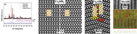
XRD of the Cr2AlB2 (Figure (a)) shows it to be predominantly single phase (93 wt%). The calculated diffraction pattern obtained from Rietveld refinement based on 24 fitting parameters showed a low χ2 value of 3.59. The calculated a, b, and c, lattice parameters for Cr2AlB2 were 2.9370(1), 11.0465(4), and 2.9683(3) Å, respectively. The major impurity phases were CrB (5.7 wt%) and Al2O3 (1.1 wt%). Figure (b) exhibits the selected area electron diffraction (SAED) patterns of Cr2AlB2 along the [110], [100], and [001] zone axes, respectively. Cr2AlB2 has an orthorhombic structure, and from the SAED patterns along [001] and [100], its a, b, and c lattice parameters were calculated to be 2.95, 11.07, and 2.97 Å, respectively. These results agree with the above XRD result. Figure (c) demonstrates Z-contrast images in the [100], [001], and [101] directions. Corresponding 2D structural models along the same zone axes—shown as colored insets in Figure (c)—are compared to the Z-contrast images and yield good agreement. The double layers of bright dots correspond to the Cr atoms; the gray dots in between correspond to the Al layers. The Z-contrast images clearly show a CrCrAlCrCrAl … sequence. The B atoms are too light to be seen in this scattering condition.
Figure 2. (a) Rietveld refinement of Cr2AlB2, the observed pattern (black), Rietveld calculated pattern (red), and difference in observed and calculated intensities (blue) are shown. Pink vertical dashes show the calculated Bragg 2θ positions for various phases considered for Rietveld refinement; (b) SAED patterns along [110], [100], and [001] projections, (c) Z-contrast images along [100], [001], and [101] projections, with unit cells shown by insets with Cr (pink), Al (blue), and B (small gray spheres), and (d) HRSTEM image showing domains along [100] and [001], marked with green and yellow arrows, respectively.
![Figure 2. (a) Rietveld refinement of Cr2AlB2, the observed pattern (black), Rietveld calculated pattern (red), and difference in observed and calculated intensities (blue) are shown. Pink vertical dashes show the calculated Bragg 2θ positions for various phases considered for Rietveld refinement; (b) SAED patterns along [110], [100], and [001] projections, (c) Z-contrast images along [100], [001], and [101] projections, with unit cells shown by insets with Cr (pink), Al (blue), and B (small gray spheres), and (d) HRSTEM image showing domains along [100] and [001], marked with green and yellow arrows, respectively.](/cms/asset/684bf1ed-c7a2-4ea6-adab-a7f751ed12f0/tmrl_a_1245682_f0002_c.jpg)
Deviations from a perfect crystal structure are evidenced by stacking fault (SF)-like defects in some Cr2AlB2 grains. The HRSTEM image in Figure (d) reveals that these SFs consist of layered domains: one is along [100] zone axis, and the other is along [001]. Both domains have the same [010] direction, but with a 90° rotation around the b axis. Thus, the domain boundaries in this case are twist boundaries with [010] as the rotation axis and (010) as the boundary plane. The thinnest domain can be as thin as 0.6 nm (half of b). Figure (d) clearly exhibits that both domains share the same Al layer. Given that a = 2.95 Å and c = 2.97 Å, the twist boundary energy should be quite low because the difference of the distance between Al atoms in [100] and [001] is <1%. Said otherwise, the (010) plane (see insert of Figure (d)) has pseudo-tetragonal metrics, which is why the existence of this 90° rotation domain boundary is not too surprising.
Figure (a) shows XRD diffractogram of the Fe2AlB2 sample. The calculated diffraction pattern from Rietveld refinement based on 18 fitting parameters again yielded a good fit to the experimental data with a χ2 = 3.09. The calculated a, b, and c lattice parameters were 2.9286(3), 11.032(1) and 2.8696(3), respectively. In this case, the major impurity phase was Al2O3 (∼12 wt%). Figure (b,c) illustrate the Z-contrast images of Fe2AlB2 in the [100] and [001] directions, respectively. From the SAED images (that are similar to the SAED patterns of Cr2AlB2, and are thus not shown here), the a, b, and c lattice parameters were calculated to be 2.92, 11.01, and 2.88 Å. These values are again consistent with the values obtained from XRD and those of Ade and Hillebrecht [Citation16]. Like for Cr2AlB2, here again, the FeB layers are interleaved by single Al layers resulting in a FeFeAlFeFeAl … stacking sequence. Since both Figures (c) and (b,c) were acquired with the high-angle annular detector, the B atoms are either out of contrast or have quite a faint contrast. To resolve the B atoms, an ABF detector was utilized to acquire HRSTEM image of Fe2AlB2 along the [100] zone axis. Figure (d) is the ABF image, exhibiting the positions of B atoms, which agree with the structure model.
Figure 3. (a) Rietveld refinement of M2AlB2, (b and c) Z-contrast images along [100] and [001], (d) ABF image in the [001] projection resolving the B atoms, and (e) a [001] tilt boundary.
![Figure 3. (a) Rietveld refinement of M2AlB2, (b and c) Z-contrast images along [100] and [001], (d) ABF image in the [001] projection resolving the B atoms, and (e) a [001] tilt boundary.](/cms/asset/7154af24-84bc-4e61-bca1-1c1aef546731/tmrl_a_1245682_f0003_c.jpg)
In contrast to Cr2AlB2, no twist boundaries were found in the Fe2AlB2 regions imaged. Instead, a tilt boundary (Figure (e)) was observed. The boundary plane is (110) and the tilt axis is [001]. Specifically, the Fe atoms closest to the boundary plane are marked with yellow dots on the left and red dots on right side of the boundary. The tilt angle is approximately 29.78°, which can be calculated from the following equation:
Thus, it is a high-angle grain boundary (HAGB). Although the HAGB is almost void-free with good coincidence of atoms at adjacent sides, it is not a coincident site lattice boundary since Fe2AlB2 is a ceramic with a complicated orthorhombic structure. In this case, the two sides of the tilt boundary shifted relative to each other by ≈0.25 nm along the [110] direction, which results in much less voids in the boundary plane. Thus, this tilt boundary does not have mirror symmetry, but most likely has quite a low interfacial energy. In spite of the similarity between the structures of Fe2AlB2 and FeB, Fe2AlB2 has a mirror symmetry in Al plane, which is different from FeB. Based on this structural character, we can recognize that both sides of the tilt boundary are Fe2AlB2, not FeB.
The SAED patterns of MoAlB are displayed in Figure (a). The a, b, and c lattice parameters measured from these patterns are 3.20, 13.96, and 3.10 Å, respectively. These results, again, are in good agreement with ours [Citation27] and those of Ade and Hillebrecht [Citation16]. Figure (b) shows the nanolaminated MoAlB structure along the [001] and [100] zone axes, respectively, imaged with an A-HRSTEM. In these images, the bright dots correlate to Mo, while the faint dots to Al. B is too light to be resolved with contrast at this condition. Both the Z-contrast images and the SAED patterns confirm the orthorhombic structure. The Z-contrast images are consistent with the MoAlB structural model (see insets in Figure (b)). The nanolaminated structure is further confirmed by EDX maps shown in Figure (c). In the Mo-Al-B system, the only thermodynamically stable phase, reported to date, is MoAlB. However, we repeatedly observe weak diffraction streaks along [010] in the SAED pattern (see Figure (d)), indicating 2D defects in the (010) plane. The Z-contrast images (Figure (e)) reveal that the SFs are not twist boundaries but SFs. These weak diffraction streaks are thus caused by SFs, which contain only one Al layer in between the MoB sublattice. Different from the MoMoAlAlMoMo … sequence in MoAlB, the SF has a MoMoAlMoMo sequence, which is the same as the sequence in M2AlB2. If synthesized it would constitute a novel Mo-Al-B phase structure, not previously reported [Citation16].
Figure 4. (a) SAED patterns of MoAlB along [110], [100], and [001] zone axes, (b) Z-contrast images of MoAlB along [100] and [001] zone axes, (c) EDX map with a line scan profile at the bottom, and (d and e) SAED and HRSTEM showing a stacking fault.
![Figure 4. (a) SAED patterns of MoAlB along [110], [100], and [001] zone axes, (b) Z-contrast images of MoAlB along [100] and [001] zone axes, (c) EDX map with a line scan profile at the bottom, and (d and e) SAED and HRSTEM showing a stacking fault.](/cms/asset/fb385ae6-1b0f-46dd-817f-0f9e77e896f8/tmrl_a_1245682_f0004_c.jpg)
Given that the arrangement of the Cr and B atoms in the Cr–B sublattice of Cr2AlB2 is similar to that of CrB (space group Cmcm) used during synthesis, it is interesting to consider a possible formation mechanism of the former. Referring to Figure (a–c), edge-sharing BCr6 trigonal prisms are found in both compounds, with the B atoms forming single zigzag chains. Thus, at high temperatures, Al may simply diffuse/intercalate into the CrB structure and cause the Cr plane to shift by 0.5 <a + c> along the [101] direction in order to form Cr2AlB2. In such a topotactic process, the lattice parameters in the a–c plane change by <±1%, but the b lattice parameter expands by 40% to accommodate the intercalated Al layers. There is no reason to believe that the same mechanism is not operative in the FeB–Fe2AlB2 case as well. In this case the unit cell parameter variations are <3% in a–c plane and 45% expansion in b direction.
Figure 5. Schematic diagrams of transformation of binary (top) to ternary (bottom) borides (a) CrB structure, note the shift half c and half a in a–c plane of top sublattice, (b) extended CrB along b axis with diffusing Al between the layers, (c) Cr2AlB2 structure; (d) MoB structure, (e) extended MoB along b axis with in-diffusing Al, and (f) MoAlB structure.
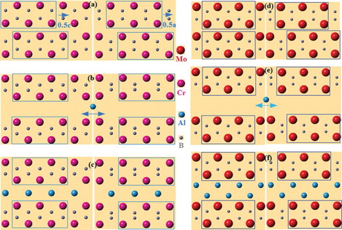
In the MoAlB compounds, the MoB (space group Cmcm) precursor and the Mo–B sublattice of the former are both composed of edge-sharing BMo6 octahedra, with single zigzag chains of B atoms (Figure (d)). Therefore, the formation of MoAlB may simply require the intercalation of two Al layers; the Mo planes need not move (see Figure (e,f)). Again, a and c lattice parameters of MoB and MoAlB differ by <2.1%, but the b lattice parameter expands by ∼65% to accommodate two Al layers in MoAlB. Another possibility is that one layer of Al atoms first diffuses into MoB to form the intermediate phase, Mo2AlB2, which is then followed by a second Al layer. In this way, the topotactic chemical reaction would be similar to the M2AlB2 case, but with a–c plane of MoB shifting 0.5 <a + c> and back. The observation of some SFs in MoAlB in which only one Al layer separates the MoB block layers is consistent with this conjecture.
These comments notwithstanding, it is acknowledged that much more work is needed to confirm these proposed mechanisms. In situ neutron diffraction during the reaction is indicated and should be carried out in the same way that, for example, Riley et al. studied how Ti3SiC2 forms from TiC [Citation30].
In summary, the atomic structures of the ternary transition metal borides Cr2AlB2, Fe2AlB2, and MoAlB were characterized using analytical aberration-corrected HRSTEM. Z-contrast images easily distinguish the Al from the transition metal atoms. By means of the ABF technique, the location of the light element B in Fe2AlB2 was also resolved, together with Fe and Al. In addition to confirming their crystal structures by direct atomic observation, compound-specific structural defects are found. These are a 90° twist boundary along [010] in Cr2AlB2, a tilt boundary in Fe2AlB2, and Mo2AlB2-like SFs in MoAlB. In the latter, the MB layers are intercalated by one (instead of two) Al layer(s).
Acknowledgements
We thank Andrew Lang of Drexel University for helpful comments on the manuscript and the staff of the Core Facilities at Drexel University.
Disclosure statement
No potential conflict of interest was reported by the authors.
Additional information
Funding
References
- Matkovich VI. Boron and refractory borides. Berlin: Springer Verlag; 1977.
- Martini C, Palombarini G, Poli G, et al. Sliding and abrasive wear behaviour of boride coatings. Wear. 2004;256:608–613. doi: 10.1016/j.wear.2003.10.003
- Okamoto NL, Kusakari M, Tanaka K, et al. Anisotropic elastic constants and thermal expansivities in monocrystal CrB2, TiB2, and ZrB2. Acta Mater. 2010;58:76–84. doi: 10.1016/j.actamat.2009.08.058
- Panda KB, Chandran KSR. First principles determination of elastic constants and chemical bonding of titanium boride (TiB) on the basis of density functional theory. Acta Mater. 2006;54:1641–1657. doi: 10.1016/j.actamat.2005.12.003
- Herbst JF, Fuerst CD, Mishira RK, et al. Coercivity enhancement of melt-spun Nd–Fe–B ribbons using low-level Cu additions. J Appl Phys. 1991;69:5823–5825. doi: 10.1063/1.347861
- Yu XW, Licht S. A novel high capacity, environmentally benign energy storage system: super-iron boride battery. J Power Sources. 2008;179:407–411. doi: 10.1016/j.jpowsour.2007.12.060
- Licht S, Yu XW, Qu DY. A novel alkaline redox couple: chemistry of the Fe6+/B2? Super-iron boride battery. Chem Commun. 2007;26:2753–2755. doi: 10.1039/b701629h
- Zapata-Solvas E, Jayaseelan DD, Brown PM, et al. Thermal properties of La2O3-doped ZrB2- and HfB2-based ultra-high temperature ceramics. J Eur Ceram Soc. 2013;33:3467–3472. doi: 10.1016/j.jeurceramsoc.2013.06.009
- Opeka MM, Talmy IG, Wuchina EJ, et al. Mechanical, thermal, and oxidation properties of refractory hafnium and zirconium compounds. J Eur Ceram Soc. 1999;19:2405–2414. doi: 10.1016/S0955-2219(99)00129-6
- Parthasarathy TA, Rapp RA, Opeka M, et al. A model for the oxidation of ZrB2, HfB2 and TiB2. Acta Mater. 2007;55:5999–6010. doi: 10.1016/j.actamat.2007.07.027
- Campbell IE, Sherwood EM. High temperature materials and technology. 1st ed. Hoboken, NJ: Wiley; 1967. Ch. 13, p. 360–363.
- Barsoum MW. The M(n+1)AXn phases: a new class of solid; thermodynamically stable nanolaminates. Prog Solid State Chem. 2000;28:201–281. doi: 10.1016/S0079-6786(00)00006-6
- Barsoum MW, El-Raghy T. Synthesis and characterization of a remarkable ceramic: Ti3SiC2. J Am Ceram Soc. 1996;79:1953–1956. doi: 10.1111/j.1151-2916.1996.tb08018.x
- Barsoum MW, Radovic M. Elastic and mechanical properties of the MAX phases. Annu Rev Mater Res. 2011;41:195–227. doi: 10.1146/annurev-matsci-062910-100448
- Barsoum MW, El-Raghy T, Ali M. Processing and characterization of Ti2AlC, Ti2AlN, and Ti2AlC0.5N0.5. Metall Mater Trans A. 2000;31:1857–1865. doi: 10.1007/s11661-006-0243-3
- Ade M, Hillebrecht H. Ternary borides Cr2AlB2, Cr3AlB4, and Cr4AlB6: the first members of the series (CrB2)nCrAl with n = 1, 2, 3 and a unifying concept for ternary borides as MAB-phases. Inorg Chem. 2015;54:6122–6135. doi: 10.1021/acs.inorgchem.5b00049
- Chai P, Stoian SA, Tan XT, et al. Investigation of magnetic properties and electronic structure of layered-structure borides AlT2B2 (T = Fe, Mn, Cr) and AlFe2−xMnxB2. J Solid State Chem. 2015;224:52–61. doi: 10.1016/j.jssc.2014.04.027
- Okada S, Iizumi K, Kudaka K, et al. Single crystal growth of (MoXCr1−X)AlB and (MoXW1−X)AlB by metal Al solutions and properties of the crystals. J Solid State Chem. 1997;133:36–43. doi: 10.1006/jssc.1997.7313
- Jeitschko W. The crystal structure of Fe2AlB2. Acta Crystallogr Sect B Struct Crystallogr Cryst Chem. 1969;25:163–165. doi: 10.1107/S0567740869001944
- Jung W, Petry K. Ternary borides of Ru with Al and Zn. Z Kristallogr. 1988;18:153–154.
- Jeitschko W. Die Kristallstruktur von MoAlB. Monatsh Chem. 1966;97:1472–1476. doi: 10.1007/BF00902599
- Okada S. Synthesis, crystal structure and characterizations of the ternary borides TMAlB (TM = Mo,W) with UBC type structure. Trans Kokushikan Univ Fac Eng. 1998;31:7–12.
- Yu Y, Lundström T. Crystal-growth and structural investigation of the new quaternary compound Mo1−xCrxAlB with x = 0.39. J Alloys Compd. 1995;226:5–9. doi: 10.1016/0925-8388(95)01598-1
- Hu C, Lai CC, Tao Q, et al. Chem Commun. 2015;51:6560–6563. doi: 10.1039/C5CC00980D
- Krivanek OL, Dellby N, Lupini AR. Towards sub-angstrom electron beams. Ultramicroscopy. 1999;78:1–11. doi: 10.1016/S0304-3991(99)00013-3
- Muller DA. Structure and bonding at the atomic scale by scanning transmission electron microscopy. Nat Mater. 2009;8:263–270. doi: 10.1038/nmat2380
- Kota S, Zapata-Solvas E, Ly A, et al. Synthesis and characterization of an alumina forming nanolaminated boride:MoAlB. Sci Rep. 2016;6:26475–26483.
- Rodriguez-Carvajal J. FULLPROF: a program for Rietveld refinement and pattern matching analysis. Powder diffraction, satellite meeting of the XV congress. Toulouse, France: IUCr; 1990.
- Riley DP, Kisi EH, Hansen TC. Self-propagating high-temperature synthesis of Ti3SiC2: II. Kinetics of ultra-high-speed reactions from in situ neutron diffraction. J Amer Ceram Soc. 2008;91:3207–3210. doi: 10.1111/j.1551-2916.2008.02637.x