
ABSTRACT
Micro-pillars with diameters varying from 0.5 to 3.5 µm were fabricated from bulk nanolaminated graphene (in the form of reduced grapheme oxide, RGO)–Al composite. Upon uniaxial compression, the pillar strengths exhibited no obvious size effect, and the pillars of larger diameters possessed smoother stress–strain response, as opposed to the jerky deformation of their smaller counterparts. A corresponding transition in the deformation mode from Al layer extrusion to shear fracture over decreasing pillar diameter was observed. These observations were explained by the competing effect of dislocation accumulation and annihilation, and a grain boundary-assisted deformation mechanism.
GRAPHICAL ABSTRACT
IMPACT STATEMENT
The transition in the deformation mode of graphene–Al composite micro-pillars from localized shear facture to Al layer extrusion over increasing pillar diameter is attributed to a grain boundary-assisted deformation mechanism.
The nanolaminated structure is widely adopted by hard biological materials [Citation1–3], which, by taking advantage of the high strength of nano-scaled constituent phases and the various toughening mechanisms provided by the laminated structure [Citation3–5], is found to be both strong and damage-tolerant. The excellent mechanical properties and exquisite microstructure of hard biological materials have inspired extensive studies on developing advanced composites (particularly polymer-based composites [Citation6,Citation7]) with a nanolaminated structure. In the case of metal matrix composites, however, because of the restriction rendered by available processing routes, such efforts have been mostly limited to proof-of-concept-typed and/or thin film-typed specimens. For example, carbon nanotube–metal composites with sandwiched structure were fabricated, where improvements in mechanical strength and toughness were reported [Citation8–10]. By employing a molecular-level mixing process, Hwang et al. [Citation11] fabricated millimetre-sized graphene–Cu composite samples and explained the good strengthening effect of graphene by the strong adhesion between graphene and Cu. However, the as-fabricated composite still suffered from a random distribution of graphene in the Cu matrix, and experimental evidence and associated analysis on possible deformation mechanism were lacking. By alternately evaporating metal thin films and transferring monolayer or bilayer graphene onto the metal-deposited substrate, Kim et al. [Citation12] fabricated graphene–Cu and graphene–Ni nanolaminated composite films and demonstrated a significant strengthening effect of graphene in nanolayered composites by a dislocation obstruction mechanism.
Using a modified powder metallurgy fabrication technique, our research group developed bulk graphene (in the form of reduced graphene oxide, RGO)–Al composites with a bioinspired nanolaminated structure, and macroscopic tensile test revealed that these composites are both stronger and tougher than the pure Al matrix fabricated by the same approach [Citation13,Citation14]. Feng et al. [Citation15] further extended this study by carrying out uniaxial compression tests on micro-pillars fabricated from the bulk RGO–Al composites with different RGO concentrations and laminate orientations. It was found that the strengthening effect and efficiency of RGO can be enhanced by either orienting the RGO layers parallel with the loading direction or raising the RGO concentration, and the robust RGO/Al interfaces provide a crack deflection mechanism that toughens the composites.
As demonstrated in Feng et al. [Citation15], when combined with site-specific microstructural analysis, micro-/nano-scaled mechanical characterization on small volume materials is a powerful tool in probing their deformation mechanism, owing to its capability in capturing the deformation characteristics across the entire gauge length [Citation15], and its flexibility in studying the mechanical behaviour of materials with various crystallographic orientations [Citation16]. Nevertheless, caution has to be exercised when one attempts to interpret bulk materials properties using the micro-/nano-mechanical data, as both mechanical strength and flow behaviour may show notable size effect when the dimension of the material is reduced to small scales [Citation17–19]. In order to correctly extrapolate bulk behaviour from micro-/nano-mechanical test results, careful design on the specimen dimension is a necessity, because the micro-/nano-scaled sample should be large enough to still properly reflect macroscopic materials properties, while it also has to be small enough so that it can be fabricated and processed within reasonable timeframe and experimental effort. Under this context, in the present paper, we used the bulk nanolaminated RGO–Al composite as a model material, and studied the size-dependent mechanical behaviour of micro-/nano-pillars with varying pillar diameters, fabricated from the bulk composite. It was found that the strength of the composite micro-pillars exhibited no obvious size effect. While, with increasing pillar diameter, the stress–strain curves got smoother, and there was a transition in the deformation mode from brittle to ductile behaviour. These observations were explained by the competing effect of dislocation accumulation and annihilation, and a grain boundary-assisted deformation mechanism.
Bulk 0.5 vol.% RGO–Al composites were fabricated via the modified powder metallurgy fabrication route [Citation13,Citation14]. Reduced graphene oxide (RGO, 99% purity, Nanjing XFNano Material Tech Co. Ltd., China) was added to an effective non-ionic surfactant TNWDIS (Chengdu Organic Chemical Co. Ltd., China) solution, and subsequently sonicated by an ultrasonic homogenizer in ice base, leading to the formation of RGO suspension. Spherical Al powders (99.99% purity, 10 µm average particle size, Henan Yuanyang Co. Ltd., China) were ball milled at a speed of 352 rpm in ethanol for 4 h to obtain flake Al powders. The as-obtained Al flakes were stirred with the RGO suspension in ethanol at a speed of 400 rpm for 30 min and then vacuum-dried at 333 K for 24 h to obtain RGO–Al composite powders with uniformly absorbed RGO nanosheets (Supporting Information, Figure S1). The RGO–Al composite powders were compacted under 500 MPa at room temperature and then hot pressed under 600 MPa at 500°C for 1 h to obtain bulk RGO–Al composites. Finally, hot rolling at 350°C by 50% reduction in thickness were employed to obtain fully densified RGO–Al composites with a nanolaminated structure. Raman spectroscopic characterization showed that the intensity ratio between D and G peaks (ID/IG) of RGO was reduced from ∼0.80 in its raw powder form to ∼0.72 in the as-fabricated composite, indicating that the various composite processing steps did not damage the quality of RGO but resulted in its further reduction (Supporting Information, Figure S2).
Cylindrical pillars with diameters ranging from 0.5 to 3.5 µm with an aspect ratios of ∼4:1 were fabricated from the polished rolling surface of the bulk sample using a dual beam focused ion beam system (FIB, FEI Scios), which also allows scanning electron microscopy (SEM) imaging. The nanolaminates were oriented perpendicular to the pillar axis (‘90° pillars’, Figure (a) inset). The vertical taper of all pillars was controlled within 2° to ensure reliable interpretation of the mechanical test data [Citation20]. Uniaxial compression tests on the pillars were conducted using an Agilent G200 Nanoindenter equipped with a 15 µm-diameter flat punch diamond tip at room temperature, and at a nominally constant strain rate of 0.005 s−1. Continuous stiffness measurement with 75 Hz in harmonic vibration frequency and 2 nm in amplitude was applied to monitor the variation of contact stiffness during compression, and the initial diameter at half height of the pillar (D0) and the initial height (L0) were measured from SEM images of as-fabricated pillars. True stress–strain curves were employed to characterize the deformation behaviour following the methodology developed by Greer et al [Citation17]. At least 10 pillars were tested to get the statistics. The morphology of the pre- and post-compression pillars was examined by SEM, and their microstructural features were characterized by site-specific TEM analysis where the TEM specimens were prepared by the lift-out method using FIB [Citation21].
Representative TEM image of the as-fabricated 0.5 vol.% RGO–Al composite is shown in Figure (a). The sample was shown to have a nanolaminated structure, where each lamella contained predominantly a single Al grain through its thickness in the normal direction (ND), and elongated grains were shown to align along the rolling direction (RD). The grain size of the Al matrix in parallel with and perpendicular to the rolling direction were found to be around ∼800 nm (dL) and ∼200 nm (dT), respectively [Citation14]. High-resolution TEM (HRTEM) characterization performed at the RGO/Al interface (Figure (b)) shows that the lamella interface was comprised of a few RGO layers (<15 layers, about ∼5 nm thick) sandwiched between ∼5 nm thick amorphous alumina layers on the surface of two adjacent Al lamellas. These amorphous alumina layers were likely to have formed during the fabrication process as a result of the easy oxidation of Al surface in air [Citation14].
Figure 1. (a) Representative TEM image of the as-fabricated 0.5 vol.% RGO–Al nanolaminated composite, where the discontinuous RGO was marked out; (b) HRTEM image taken at the RGO/Al interface, where the various constituents were marked out and indicated by arrows.
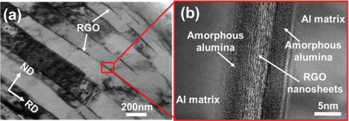
Figure (a) shows the representative true stress–strain curves for nanolaminated RGO–Al composite micro-pillars with diameters ranging from 0.5 to 3.5 µm. The yield strengths of 0.5-, 1.5-, 2.5- and 3.5 µm-diameter pillars were 254±25, 250±12, 253±8 and 250±10 MPa, respectively, indicating that the variation in extrinsic size had no obvious effect on the mechanical strength of RGO–Al composite pillars. The yield strength (σy, as arrowed in Figure (a)), was defined as the stress value at the first discrete displacement burst that occurred post-1% strain in each curve, and a threshold of Δε ≥ 0.002 was used to identify the burst events [Citation22]. On comparison, different observations were made in Mayer et al. [Citation23], where higher compressive strengths were observed in smaller metal-ceramic nanolaminated composites micro-pillars, as justified by a lower probability of flaws using Weibull statistics. This discrepancy may be the result of the different fabrication process in these two studies, where no obvious flaws were observed in our RGO–Al nanolaminated composite micro-pillars, regardless of smaller or larger micro-pillars, due to the improvement of the interfacial adhesion between the RGO layers and the Al matrix through the rigorous control of the densification process in the fabrication of bulk RGO–Al composites. The observation that the pillar diameter did not affect its strength may indicate that when both internal and external length scales are present, the smaller of the two (in this case the lamella thickness of ∼200 nm) would determine the sample strength, a proposal in agreement with previously reported results from multi-layered [Citation24,Citation25] and nanocrystalline [Citation26] micro-pillars.
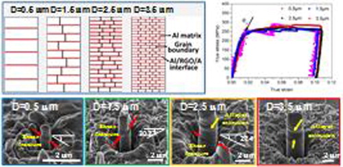
Figure 2. (a) Representative compressive true stress–strain curves for RGO–Al composite micro-pillars with varying diameters. The inset schematically demonstrates the microstructures of the composite pillars with different diameters, where the Al lamella shows a gradual transition from single crystal to polycrystalline when the pillar diameter increases from 0.5 to 3.5 µm. (b) Variation of average stress burst increment and strain hardening rate as a function of pillar diameter.
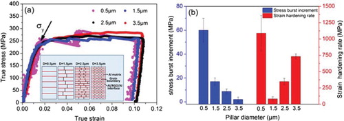
It is also manifested in Figure (a) that the composite pillars of larger diameters possessed smoother stress–strain response, as opposed to the jerky deformation characteristic of their smaller counterparts. Previous studies on the mechanical behaviour of micro-/nano-pillars suggest that such intermittent plastic flow is correlated with the avalanche of dislocations in small-scale crystals and their annihilation at the internal interfaces and/or free sample surfaces [Citation16–18]. A quantitative evaluation was done by measuring the size of the discrete bursts on the stress–strain response as a function of pillar diameter, and the result is summarized in Figure (b). Since the stress burst increment in the ascending section of each burst measures the load needed to trigger new dislocation sources and subsequent dislocation motion to sustain further plastic deformation, it was used here as a more reliable gauge for the magnitude of the preceding dislocation annihilation event [Citation15]. The observation that the burst size increased considerably with decreasing pillar diameter may indicate that both dislocation accumulation and annihilation were operating simultaneously in the composites, and their overall deformation behaviour was governed by the competition of the two processes. Particularly, the RGO–Al nanolaminated composite pillars with larger diameters contain free pillar surfaces, heterogeneous inter-lamella interfaces and grain boundaries. Free pillar surfaces are widely reported to serve as effective dislocation sinks during the deformation of micro-/nano-scaled pillars [Citation27]. In the case of heterogeneous RGO/Al inter-lamella interfaces, our previous study on the bulk RGO–Al composite indicates that the plastic deformation of the composite is governed by a competition between dislocation accumulation in the Al grains and dislocation annihilation at the RGO/Al interface [Citation14]. On comparison, the interaction between grain boundaries and dislocations is complex and highly depends on the grain size, and specific type and configuration of the grain boundaries. It was reported that grain boundaries may act as dislocation sinks [Citation16] and dislocation nucleation sites [Citation28] during deformation, similar to the role played by free pillar surfaces [Citation27,Citation28]. However, these mechanisms were likely to only dominate in nanocrystalline [Citation29,Citation30] and bi-crystal/polycrystalline pillars containing grains of a few tens of nanometres [Citation28,Citation31], and shouldn't be the governing mechanism in the RGO–Al composites reported in this work. Specifically, the grain size of the Al matrix in parallel with the Al layer direction was found to be around ∼800 nm, so grain boundaries were likely to serve as the hindrance of dislocation motion, causing the accumulation of dislocations near the grain boundaries [Citation32]. Therefore, for smaller pillars (such as the 0.5 µm-diameter ones), the large surface area and abundant inter-lamella interfaces were likely to make dislocation annihilation/absorption the governing mechanism, leading to relatively large burst sizes. With increasing pillar diameter, dislocation generation and accumulation at grain interior and grain boundaries gradually overtook its annihilation at RGO/Al interfaces and free pillar surfaces, causing a diminishing trend in burst sizes. This proposal can be further appreciated by the evolution of strain hardening rate over varying pillar diameters, which was obtained by linearly fitting the peak stresses during each burst [Citation16]. Figure (b) demonstrates that, as expected, when the pillar diameter increased from 1.5 to 3.5 µm, the strain hardening rate was enhanced from 83 ± 30 to 732 ± 40 MPa, indicating progressively more pronounced dislocation build-ups in the Al grains. An exceptional case is the 0.5 µm-diameter pillars which showed the highest strain hardening rate of 1088 ± 274 MPa among all samples studied. These smallest pillars only went through one burst event after yielding (Figure (a)), and the strain hardening rate was calculated based on two stress values (σy and the peak stress at the burst) for each pillar. At this length scale, the plastic deformation was likely to be dislocation source-controlled and the 0.5 µm-diameter pillars suffered from a more dislocation ‘starved’ state than the larger ones due to higher probability of mobile dislocations getting annihilated at the internal-lamella interfaces and free pillar surfaces [Citation17,Citation33]. As the as-fabricated composite had a considerable initial dislocation density [Citation14,Citation15], the first yielding event occurred at a relatively low stress value (σy), and upon further deformation the Al grains quickly became depleted of mobile dislocations. This gave rise to an elevated peak stress at the ensuing stress (strain) burst to activate subsequent dislocation nucleation and motion, rendering a high strain hardening rate for the 0.5 µm-diameter pillars.
Figure (a–d) and their insets show the representative SEM images of pre- and post-compression RGO–Al composite pillars of different diameters. It is clearly manifested that localized shear fracture occurred in the composite pillars with the diameter of 0.5 and 1.5 µm (Figure (a,b)). In stark contrast, fairly uniform lateral bulge/layer extrusion across the pillar gauge length was evident in the 3.5 µm-diameter pillar, indicating that these pillars experienced a lot of plastic deformation upon compression (Figure (d)). At the intermediate diameter of 2.5 µm, both lateral bulge/layer extrusion and localized shear fracture were observed (Figure (c)), suggesting that there was a gradual transition in the deformation mode with varying pillar diameter. These results are corroborated by post-mortem TEM analysis, where Figure (a) and (b) exhibit the representative images of deformed 0.5- and 3.5 µm-diameter composite pillars, respectively, two sizes that corresponded to the distinctly different deformation modes. Consistent with the observations made in Figure , the morphology of the 3.5 µm-diameter pillars was characterized by uniform deformation and extrusion of the Al layers (Figure (b)), while the 0.5 µm-diameter pillar was subject to localized shear fracture (Figure (a)).
Figure 3. Typical SEM images of post-compression RGO–Al composite pillars with four different diameters (a) 0.5 µm, (b) 1.5 µm, (c) 2.5 µm and (d) 3.5 µm. The localized shear fracture is indicated by red arrows in (a), (b) and (c), while the extrusion of Al layer is indicated by yellow arrows in (c) and (d). Illustrative shear angle (the angle between the shear fracture plane and the pillar cross-section) estimates of post-compression pillar with local shear deformation are provided in (a)–(c). Insets show the corresponding SEM images of the RGO–Al composite pillars before compression.
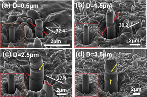
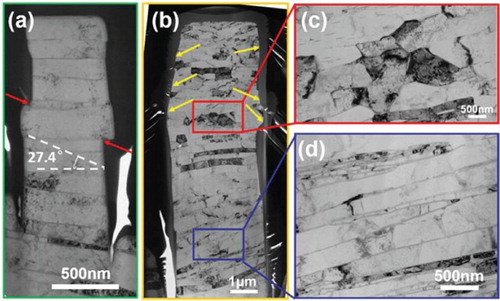
Figure 4. Representative TEM images of post-compression RGO–Al composite pillars. (a) and (b) show the morphologies of the entire pillars with diameters of 0.5 and 3.5 µm, respectively. (c) and (d) are magnified renditions of the regions boxed in (b). The localized shear fracture was indicated by red arrows in (a), while the extrusion of Al layer was indicated by yellow arrows in (b).
Interestingly, drastically different observations were made in nanolaminated Cu/Zr pillars [Citation25] and Al/SiC micro-pillars [Citation34,Citation35], where the pillar diameter was found to have a negligible effect on the deformation mode. Such a discrepancy may be rationalized by the different roles that grain boundaries played in these two studies. Unlike the Al/SiC micro-pillars [Citation34,Citation35] where a single lamella contains multiple equiaxed nano-grains (for the 1 µm-diameter pillar, there was about 16 nano-grains in the direction parallel with the laminates), the nanolaminated RGO–Al composite pillars fabricated in this work had elongated Al grains, with grain sizes of ∼800 and ∼200 nm in parallel with and perpendicular to the laminate, respectively. As a result, the decrease in pillar diameter from 3.5 to 0.5 µm was associated with a corresponding reduction in the average number of grains across each lamella, where the larger (1.5-, 2.5- and 3.5 µm-diameter) pillars contained multiple (2–5) grains in each Al layer while the 0.5 µm-diameter ones generally had a single Al grain in an individual layer (Figure (a) inset). For the smallest pillars (0.5 µm-diameter), each layer was single grain and had the smallest aspect ratio of the individual Al layers [(pillar diameter: repeat layer spacing) = (∼500 nm: ∼200 nm) ≈ 2.5]. It was then easier to find a slip system in which the dislocations could escape through the free surface or sidewall of the pillar, resulting in non-uniform shear fracture of the pillars. On comparison, with increasing pillar diameter, the aspect ratio of the individual Al layers increased and correspondingly more grains were needed to coordinate the deformation in one lamella. This was likely to make deformation progressively more difficult and thus the activation of multiple complex slip systems was required, causing shear across the interface and the lateral bulging of the pillars (Figure (c,d)).
More specifically, dislocations accumulated in the Al layers tended to pile-up at the internal boundaries (inter-lamella interfaces and/or Al–Al grain boundaries), because those boundaries were characterized by certain activation energies and limited capacity for dislocation absorption/storage [Citation36,Citation37]. Such dislocation pile-ups inevitably caused local stress concentration, which had to be accommodated by the emission of dislocations from grain boundary [Citation38], grain fragmentation [Citation39] and/or the formation of localized shear bands [Citation40]. Therefore, the multi-grains contained in each Al layer of the relatively large pillars helped relieve stress concentration and favoured uniform deformation. Figure (c) demonstrates a magnified rendition of the severely deformed region in the post-compression 3.5 µm-diameter (Figure (b)). Compared to the relatively straight grain boundaries and inter-lamella interfaces observed in the almost intact, deformation-free zone at the bottom of the pillar (Figure (d)), the deformed microstructure (Figure (c)) showed nearly equiaxed grains in a markedly distorted arrangement, a clear evidence for grain fragmentation and a grain boundary-assisted deformation mechanism (Figure (c)). With decreasing pillar diameter, however, each Al lamella transitioned from polycrystalline to a single crystal, so that the plastic deformation and subsequent stress concentration could only be mediated in the grain interior and by the interaction between dislocations and the RGO/Al interfaces. This was likely to have resulted in the shear fracture behaviour of the smaller pillars. In particular, in the deformed 0.5 µm-diameter pillar shown in Figure (a), it can be clearly observed that the shear facture path was confined in the single crystalline Al lamella, forming a shear angle (the angle between the shear fracture plane and the pillar cross-section) of about 27.4°, which significantly deviated from the 45° orientation as predicted by the maximum resolved shear stress criterion [Citation15]. Although it was difficult to identify the exact crack growth paths because of the Pt filling and/or material re-deposition in the crack during TEM sample preparation using FIB, shear fracture of the composite pillars was likely to occur through crack propagation across the Al layer in a transcrystalline mode. In this way, by studying the post-compression morphology of more than 10 pillars from each size group (Figure (a–c)), the shear angles of the 0.5-, 1.5- and 2.5 µm-diameter composite pillars were found to be 31.6 ± 5.8°, 28.3 ± 4.6° and 25.8 ± 3.2°, respectively, showing a slight (if any) decrease with increasing pillar diameter. These observations appear to suggest that, the Al/Al grain boundaries in an individual Al lamella had an increasingly more significant crack deflection effect due to the larger aspect ratios of the individual Al layers [pillar diameter: repeat layer spacing] and the complex slip systems activated in larger pillars. However, the crack deflection effect of Al/Al grain boundaries was likely to be weaker than that of RGO/Al interfaces [Citation15].
In summary, micro-pillars with diameters varying from 0.5 to 3.5 µm were fabricated from bulk nanolaminated RGO–Al composite. Upon uniaxial compression, the pillar strengths exhibited no obvious size effect, and were 254 ± 25, 250 ± 12, 253 ± 8 and 250 ± 10 MPa for 0.5-, 1.5-, 2.5- and 3.5 µm-diameter pillars, respectively. The composite pillars of larger diameters possessed smoother stress–strain response, as opposed to the jerky deformation characteristic of their smaller counterparts. Considering the evolution of burst increment and strain hardening rate as a function of pillar size, we proposed that dislocation accumulation (most likely in the interior of elongated Al grains and Al/Al grain boundaries) and annihilation (at the RGO/Al internal-lamella interfaces and free pillar surfaces) were operating simultaneously in the pillars, and their overall deformation behaviour was governed by the competition of the two processes. A corresponding transition in the deformation mode from shear fracture of the smaller pillars, to uniform lateral bulge/layer extrusion of the larger ones was observed, which was likely to indicate a grain boundary-assisted deformation mechanism.
Supplementary_Material
Download MS Word (866.8 KB)Acknowledgements
The authors would like to thank Tao Liu (Shanghai Jiao Tong University, China) for assistance in sample preparation.
Disclosure statement
No potential conflict of interest was reported by the authors.
Additional information
Funding
Related Research Data
References
- Dunlop JWC, Fratzl P. Biological composites. Annu Rev Mater Res. 2010;40:1–24.
- Mayer G. Rigid biological systems as models for synthetic composites. Science. 2005;310:1144–1147.
- Ritchie RO. The conflicts between strength and toughness. Nat Mater. 2011;10:817–822.
- Ji BH, Gao HJ. Mechanical properties of nanostructure of biological materials. J Mech Phys Solids. 2004;52:1963–1990.
- Espinosa HD, Juster AL, Latourte FJ, et al. Tablet-level origin of toughening in abalone shells and translation to synthetic composite materials. Nat Commun. 2011;2:173.
- Bonderer LJ, Studart AR, Gauckler LJ. Bioinspired design and assembly of platelet reinforced polymer films. Science. 2008;319:1069–1073.
- Cheng QF, Duan JL, Zhang Q, et al. Learning from nature: constructing integrated graphene-based artificial nacre. ACS Nano. 2015;9:2231–2234.
- Li YH, Housten W, Zhao YM, et al. Cu/single-walled carbon nanotube laminate composites fabricated by cold rolling and annealing. Nanotechnology. 2007;18:205607.
- Kang TJ, Yoon JW, Kim DI, et al. Sandwich-type laminated nanocomposites developed by selective dip-coating of carbon nanotubes. Adv Mater. 2007;19:427–432.
- Jiang L, Li ZQ, Fan GL, et al. Strong and ductile carbon nanotube/aluminum bulk nanolaminated composites with two-dimensional alignment of carbon nanotubes. Scr Mater. 2012;66:331–334.
- Hwang J, Yoon T, Jin SH, et al. Enhanced mechanical properties of graphene/copper nanocomposites using a molecular-level mixing process. Adv Mater. 2013;25:6724–6729.
- Kim Y, Lee J, Yeom MS, et al. Strengthening effect of single-atomic-layer graphene in metal-graphene nanolayered composites. Nat Commun. 2013;4:2114.
- Li Z, Fan GL, Tan ZQ, et al. Uniform dispersion of graphene oxide in aluminum powder by direct electrostatic adsorption for fabrication of graphene/aluminum composites. Nanotechnology. 2014;25:325601.
- Li Z, Guo Q, Li ZQ, et al. Enhanced mechanical properties of graphene (reduced graphene oxide)/aluminum composites with a bioinspired nanolaminated structure. Nano Lett. 2015;15:8077–8083.
- Feng SW, Guo Q, Li Z, et al. Strengthening and toughening mechanisms in graphene-Al nanolaminated composite micro-pillars. Acta Mater. 2017;125:98–108.
- Kunz A, Pathak S, Greer JR. Size effects in Al nanopillars: single crystalline vs. bicrystalline. Acta Mater. 2011;59:4416–4424.
- Greer JR, Oliver WC, Nix WD. Size dependence of mechanical properties of gold at the micron scale in the absence of strain gradients. Acta Mater. 2005;53:1821–1830.
- Nix WD, Greer JR, Feng G, et al. Deformation at the nanometer and micrometer length scales: effects of strain gradients and dislocation starvation. Thin Solid Films. 2007;515:3152–3157.
- Uchic MD, Dimiduk DM, Florando JN, et al. Sample dimensions influence strength and crystal plasticity. Science. 2004;305:986–989.
- Zhang H, Schuster BE, Wei Q, et al. The design of accurate micro-compression experiments. Scr Mater. 2006;54:181–186.
- Guo XL, Guo Q, Li ZQ, et al. Interfacial strength and deformation mechanism of SiC–Al composite micro-pillars. Scr Mater. 2016;114:56–59.
- Guo Q, Landau P, Hosemann P, et al. Helium implantation effects on the compressive response of Cu nanopillars. Small. 2013;9:691–696.
- Mayer CR, Yang LW, Singh SS, et al. Anisotropy, size, and aspect ratio effects on micropillar compression of Al/SiC nanolaminate composites. Acta Mater. 2016;114:25–32.
- Guo W, Jägle E, Yao JH, et al. Intrinsic and extrinsic size effects in the deformation of amorphous CuZr/nanocrystalline Cu nanolaminates. Acta Mater. 2014;80:94–106.
- Zhang JY, Lei S, Niu J, et al. Intrinsic and extrinsic size effects on deformation in nanolayered Cu/Zr micropillars: from bulk-like to small-volume materials behavior. Acta Mater. 2012;60:4054–4064.
- Gu XW, Loynachan CN, Wu ZX, et al. Size-dependent deformation of nanocrystalline Pt nanopillars. Nano Lett. 2012;12:6385–6392.
- Greer JR, De Hosson JTM. Plasticity in small-sized metallic systems: intrinsic versus extrinsic size effect. Prog Mater Sci. 2011;56:654–724.
- Kim Y, Lee S, Jeon JB, et al. Effect of a high angle grain boundary on deformation behaviour of Al nanopillars. Scr Mater. 2015;107:5–9.
- Ungár T, Li L, Tichy G, et al. Work softening in nanocrystalline materials induced by dislocation annihilation. Scr Mater. 2011;64:876–879.
- Tschoppa MA, McDowell DL. Grain boundary dislocation sources in nanocrystalline copper. Scr Mater. 2008;58:299–302.
- Zhang JY, Liu G, Sun J. Strain rate effects on the mechanical response in multi- and single-crystalline Cu micropillars: grain boundary effects. Int J Plasticity. 2013;50:1–17.
- Ng KS, Ngan AHW. Deformation of micron-sized aluminium bi-crystal pillars. Philos Mag. 2009;89:3013–3026.
- Lei S, Zhang JY, Niu JJ, et al. Intrinsic size-controlled strain hardening behavior of nanolayered Cu/Zr micropillars. Scr Mater. 2012;66:706–709.
- Lotfian S, Rodríguez M, Yazzie KE, et al. High temperature micropillar compression of Al/SiC nanolaminates. Acta Mater. 2013;61:4439–4451.
- Singh DRP, Chawla N, Tang G, et al. Micropillar compression of Al/SiC nanolaminates. Acta Mater. 2010;58:6628–6636.
- Jennings AT, Gross C, Greer F, et al. Higher compressive strengths and the Bauschinger effect in conformally passivated copper nanopillars. Acta Mater. 2012;60:3444–3455.
- Carlton CE, Ferreira PJ. What is behind the inverse Hall–Petch effect in nanocrystalline materials? Acta Mater. 2007;55:3749–3756.
- Wang YM, Hamza AV, Ma E. Temperature-dependent strain rate sensitivity and activation volume of nanocrystalline Ni. Acta Mater. 2006;54:2715–2726.
- Qin EW, Lu L, Tao NR, et al. Enhanced fracture toughness and strength in bulk nanocrystalline Cu with nanoscale twin bundles. Acta Mater. 2009;57:6215–6225.
- Packard CE, Schuh CA. Initiation of shear bands near a stress concentration in metallic glass. Acta Mater. 2007;55:5348–5358.