
ABSTRACT
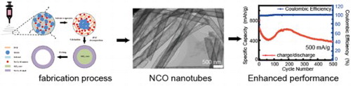
Nickel–Cobalt oxide nanotubes are prepared by a simple electrospinning technique based on a phase-separation mechanism. Extra tetraethyl orthosilicate (Si(OC2H5)4) is introduced and removed by design to obtain nanotube structure. The prepared nanotubes deliver remarkable electrochemical performance as the lithium-ion batteries anode materials. It possesses a capacity of 924 mAh/g after 95 cycles at 100 mA/g. At 2000 mA/g, it has a high capacity of 770 mAh/g, and still has 255 mAh/g at 1000 mA/g after 500 cycles. The outstanding electrochemical performance is attributed to the unique hierarchical tubular nanostructures design. This simple method opens new opportunities for fabricating practical nanostructured anode materials.
GRAPHICAL ABSTRACT
IMPACT STATEMENT
This paper gives a simple phase separation method to fabricate polycrystalline nanotube structures and the nanotubes are suitable as lithium battery anode materials with remarkably enhanced lithium storage.
1. Introduction
Lithium-ion batteries (LIBs) have attracted increasing attention due to high capacity density, lightweight, wide voltage window [Citation1,Citation2]. However, the limited capacity of commercial graphite anode materials impedes the further development of LIBs with higher capacity density [Citation3]. Great efforts have been dedicated to developing and exploring novel high capacity anode materials. High capacity anode materials, for instance, silicon, lithium metal and transition metal oxide (TMO) have been considered prospective novel anode materials in terms of their high capacities and high energy density [Citation4–7].
TMO anode materials own the merits of high theoretical capacities and easy manufacture. Among TMO materials, Nickel–Cobalt oxide (NCO) based anode materials usually have high theoretical capacities. Like other TMO anode materials, NCO materials also suffer from low ionic/electronic conductivity, large volume expansion during cycling and fast capacity decay, which lead to worse electrochemical performance ultimately [Citation8,Citation9]. Hence, practical applications of NCO materials have been hindered apparently. To settle the problems mentioned above, extensive studies have been focused on the high performance TMO anode materials research, including NCO materials. Nanostructure design is regarded as an effective route to improve the electrochemical performance of TMO anode materials. The major benefits of nanostructures design are as follows: (1) The ionic/electronic transportation path has been reduced in nanostructures, such as nanowire, nanofiber, nanotube, nanoarray, nanosphere, etc. (2) The volume expansion stress could be released by nanostructures with void or with rigid/flexible coating materials, such as hollow nanospheres, hollow nanotube, core–shell nanostructure with coating, nanowire, composite with carbon materials, etc. (3) More electrolyte could be stored in the voids in nanostructures, which ensures smoother ionic conductivity pathways [Citation10,Citation11]. Specially, tubular nanostructured materials have attracted increasing attention as LIBs anode materials due to their unique structure configuration with large open ends that can facilitate Li+-carrying electrolyte penetration. This structural design could provide very large electrolyte/electrode contacting area to promote fast Li+ flux, thus beneficial for making full use of whole electrode and improve the rate capability.
In recent years, electrospinning has been widely used as a simple, versatile and cost-effective technology to produce one-dimensional (1D) hollow nanomaterials and their composites with controllable morphology and properties [Citation12]. Generally, the strategy for fabricating 1D hollow nanomaterials by electrospinning technique can be classified into two major methods: tubes by fibers templates (TUFT) process [Citation13,Citation14], and coaxial electrospinning [Citation15–17]. However, these two methods currently still face some challenges. For example, different coating procedures used in TUFT process demand for strict apparatus and need a time-consuming multistep coating process [Citation13]. Coaxial electrospinning requires special design for complicated spinneret, suitable multiple fluids, and precise control of core and shell solutions flow rate to form core–shell structure composite fibers, which highly restricts its applications and extension. Based on these drawbacks, it seems to be an ideal solution to avoid the mentioned disadvantages by using simple and easy-control single-spinneret electrospinning method to synthesize 1D hollow nanomaterials. This process only needs to choose two immiscible solutions that can cause phase separation during electrospinning, thus yielding core–shell composite nanofibers or hollow nanofibers after suitable core removal by using different post-treatments [Citation18]. Compared with other synthesized methods, neither a complex coating procedure nor a special spinner is required in this phase-separation-combined electrospinning method. Till now, many types of 1D hollow single-component oxides such as SnO2 [Citation19] and TiO2 [Citation20], etc. have been extensively fabricated by this simple method. However, a detailed study on the synthesis of 1D hollow binary metal oxides such as NCOs using this simple method and their potential lithium-storage properties has been rarely reported.
Here, we report a simple method to prepare hollow nanofibers by combining the electrospinning process with etching process using the KOH. Firstly, we obtain Ni–Co–Si–O nanofibers by electrospinning with adding tetraethyl orthosilicate (Si(OC2H5)4, TEOS). The TEOS would gather in the core area of the whole nanofiber owing to the phase separation while the Ni and Co precursors prefer to disperse in the shell area. After calcining process, the nanofibers are etched by potassium hydroxide (KOH) solutions to remove the SiOx in the core. Finally, the Ni–Co oxide nanotubes (NCO-NT) are fabricated. The NCO-NT exhibits outstanding electrochemical performance. At 100 mA/g, the specific capacity maintains 924 mAh/g after 95 cycles. At a high current density of 1000 mA/g, the NCO-NT cell exhibits stable cycling for 500 cycles. Besides, the NCO-NT cells show excellent rate performance, with an average capacity of 870, 773, 621, 431, 323 and 770 mAh/g at the current density of 100, 200, 500, 1000, 2000 and back to 100 mA/g separately. The characterization results verify the hollow structure and compositions, and indicate the mechanism behind the excellent performance. The microstructure maintains well after cycling, suggesting the effectiveness of hollow structure. This simple and universal method could also be explored for other nanotubes fabrication.
2. Experimental section
All the chemicals are used as received without further purification. Ni(CH3COO)2·4H2O, Co(NO3)2·6H2O, polyvinyl pyrrolidone (PVP), N,N-dimethylformamide (DMF), ethanol, and N-methyl pyrrolidone (NMP) are bought from Sinopharm Chemical Reagent Co., Ltd. Super P, PVDF are bought from Heifei Kejing Materials Technology Co, Ltd. Carbonate electrolyte (1 M LiPF6 in 1/1 v/v EC (ethylene carbonate)/DEC (diethyl carbonate)) is bought from Shanshan Advanced Materials Co, Ltd.
Sample preparation: Firstly, ethanol and DMF are mixed in a solution with a volume ratio of 9. Then the Ni(CH3COO)2·4H2O, Co(NO3)2·6H2O are dissolved at a molar ration of 1:2 into the mixed solution with a Ni2+ concentration of 0.067 mol/l. After stirring for 1 h, PVP is added into the solution with a concentration of 0.08 g/ml stirred for another 2 h. Finally, the TEOS is added into the solution with a molar ratio of 4 versus Ni2+ for another 2 h. The precursor solutions are transferred into a syringe for electrospinning. The electrospinning parameters are as follows: the roll speed of 300 rpm, the applied voltage of 1 kV/cm, the solution injection speed of 1 ml/h. The as-spun nanofiber mat is calcined at 300°C and keeps for 0.5 h at 300°C, then calcined at 500°C for 2 h. The as-calcined nanofiber mat is etched in the 1 M KOH solution. Finally, the nanofiber mat is washed by DI water and ethanol alternately for 3 times and dried in oven. The microstructure is tuned by changing different molar ratio of TEOS/Ni2+, which is further explained in the supporting information (Figure S2).
Materials characterization: The morphology and mic-rostructure of samples are characterized by Scanning Electron Microscopy (SEM, MERLIN VP Compact, ZEISS, Germany). The phase structure is analyzed by the X-ray Diffraction (XRD, Cu Kα, D/max-V2500, Rigaku, Japan). X-ray Photoelectron Spectroscopy (XPS) is employed to analyze the elements composition of samples (ESCALAB 250Xi, Thermo Fisher Scientific, USA). Transmission Electron Microscopy (TEM) and EDS mapping are used for nanostructure analysis (Tecnai F20(FEI)).
Electrochemical performance tests: The electrochemical performance is tested with coin cells. The coin cells are assembled in a glovebox with H2O and O2 less than 0.1 ppm. Firstly, samples, super P and PVDF are mixed at a weight ratio of 7:2:1 in NMP stirred for 12 h. Then, the slurry is cast onto Cu foil. The Cu foil with slurry is dried in a vacuum oven for 12 h at 110°C. The mass loading is around 1 mg/cm2. Galvanostatical cycling is tested by Land testers, with a voltage window between 3 and 0.05 V. The impedance is tested by IM6 (Zahner Messtechnik), with the frequency range of 100 kHz to 0.01 Hz.
3. Results and discussion
3.1. Microstructure of NCO-NTs
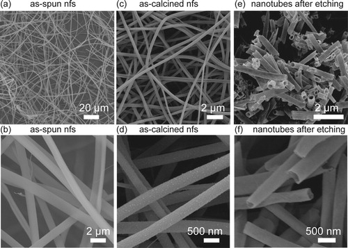
The microstructure of nanofibers after different treatments characterized by SEM are displayed in Figure . Firstly, the nanofibers after electrospinning are solid, and the surface is quite smooth. The nanofibers have a diameter of around 1 μm and a length of several hundreds of microns. The microstructure of as-spun nanofibers is influenced by TEOS. With the addition of TEOS, the electrospinning precursors are mixed better. The as-spun nanofibers have an intact and uniform morphology (Figure (a)). After calcination, the nanofibers still present a smooth morphology and a quite continuous structure. The diameter distribution of as-calcined nanofibers is around 300–400 nm. Different from the as-calcined nanofibers with TEOS addition, the pure NiCo2O4 nanofibers (NiCo2O4-NF) after calcining process tend to shrink severely (Figure S1). The pure NiCo2O4 nanofibers have an irregular morphology, and the particles connection is weak. The integrity of as-calcined pure NiCo2O4 nanofibers is more inferior than as-calcined nanofibers with TEOS addition. The weak connectivity in pure NiCo2O4 nanofibers could be attributed to the organic compounds evaporation and decomposition in the electrospinning precursors during calcination. The nanofibers microstructure remains the same after introducing the TEOS (Figure (b)). After etching with KOH, the NCO-NTs are obtained. It seems that the nanotubes (Figure (e)) hold the 1D structure but the core area is etched thoroughly, meanwhile, the surface is still smooth and continuous. The hollow structure verifies that the TEOS in the precursor prefers to accumulate in the core area in the nanofibers. So it could be inferred that TEOS is in the core and Ni–Co source is in the shell in the electrospun nanofibers.
Figure 1. Microstructure of NCO-NTs after different treatments and NiCo2O4 nanofibers (NiCo2O4-NF) characterizaed by SEM. (a, b) SEM images of as-spun nanofibers. (c, d) SEM images of as-calcined nanofibers. (e, f) SEM images of nanotubes after etching.
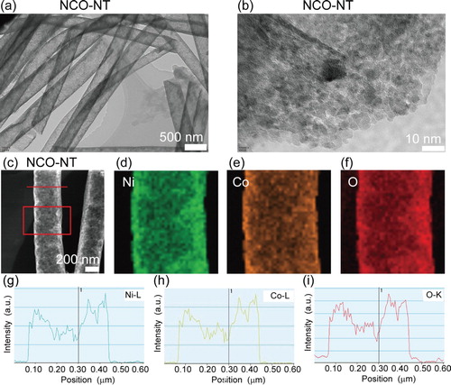
To further characterize the crystalline microstructure in the nanotubes (NCO-NT), high-resolution transmission electron microscopy (HRTEM) technique is employed. In the HRTEM images (Figure (a)), we could see the nanotubes with a uniform size. The nanotubes are assembled with many nanocrystals, and there are many nano pores in the nanotubes favorable for electrolytes absorption. Energy Dispersive X-Ray Spectroscopy (EDX) is used to identify the elements components (Figure (c–i)). The Ni, Co and O constitute the whole nanotubes (Figure (c–f)). The hollow structure of NCO-NT is proved with the signals decreasing in the middle area through line scan results in Figure (g–i). The Ni–Co–O is in the shell part in the nanofibers to resemble a nanotube structure. The HRTEM and EDX results confirm the hollow structure in the as-etched NCO-NT, in consistency with the SEM results in Figure .
Figure 2. HRTEM and EDX mapping/line scan of nanotubes. (a, b) HRTEM images of NCO-NT. (c–f) EDX mapping of NCO-NT , Ni (d), Co (e) and O (f). (g–i) Line scan of NCO-NT, Ni (g), Co (h) and O (i).
3.2. Preparation process of NCO-NT by phase separation method
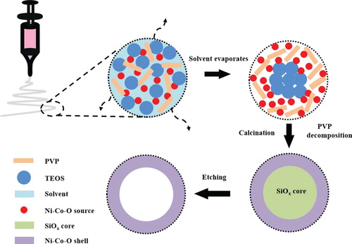
To elucidate the nanotubes formation process, we propose a simple phase-separation mechanism (Figure ). Firstly, the TEOS is added into the electrospinning precursors and mixed together with the Ni, Co precursors. But the TEOS tend to accumulate in the core area and separate with the Ni–Co source in the whole nanofibers after electrospinning due to the phase separation. Then the TEOS convert into SiOX in the core part after calcination. After etching by KOH, the core SiOX is depleted but the Ni–Co–O shell could be retained completely. So the NCO-NTs are obtained finally.
Figure 3. Schematic diagram of NCO-NTs preparation process.
3.3. Electrochemical performance of NCO-NT
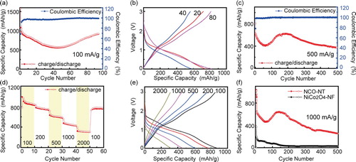
The electrochemical performance is tested with galvanostatical cycling. Firstly, the NCO-NTs are tested at a low current density of 100 mA/g (Figure (a)). The NCO-NT cell exhibits a high specific capacity of 1573 mAh/g in the first discharge process in the first cycle. The higher capacity could be attributed to the polycrystalline compositions of NCO-NT observed in the HRTEM results. Interestingly, the specific capacity drops to 577 mAh/g after 50 cycles, but it rises slowly back to 924 mAh/g after 95 cycles. The ‘decline first and rise afterwards’ trend could be caused by the activation process in the porous anode [Citation5,Citation21]. The nanotubes might be activated after several cycles at low current density, then the capacity returns back to the original capacity slowly. Besides, the average Coulombic efficiency (CE) is about 97.6%. The voltage-specific capacity profiles after different cycles in Figure (b) prove that the capacity experiences a ‘decline first and rise afterwards’ trend. When the current density is elevated to 500 mA/g, the NCO-NT also displays a high specific capacity in the initial stage. The NCO-NT cell delivers a high discharge capacity of 807 mAh/g in the first cycle. Then the NCO-NT cell recovers to 625 mAh/g after 185 cycles. It also shows the tendency of ‘decline first and rise afterwards’ due to the activation process. After the activation, the cell capacity drops slowly but it still has a capacity of 376 mAh/g after 500 cycles. The average CE is 99.4% for 500 cycles. Rate tests are employed to evaluate the electrochemical performance at different current densities. The NCO-NT delivers an average capacity of 870, 773, 621, 431, 323 and 770 mAh/g at the current density of 100, 200, 500, 1000, 2000 and back to 100 mA/g separately. The voltage-specific capacity profiles at various current densities verify a continuous electrochemical reaction and polarization with increasing current densities. The NCO-NT cell also presents remarkable long cycling stability at a high current density of 1000 mA/g. The cell is first cycled at 100 mA/g for 3 cycles and then go to 1000 mA/g later. it shows a discharge capacity of 1011 mAh/g in cycle 1 at 100 mA/g. It delivers 849 mAh/g when the current density increases to 1000 mA/g. The capacity rises and drops down slowly. The cell still has 255 mAh/g after 500 cycles. In contrast, the cell assembled with pure NiCo2O4 nanofibers (NiCo2O4-NF) displays inferior performance. Its capacity declines quickly under 100 mAh/g within only 58 cycles. The poor electrochemical performance is due to the volume expansion during cycling and the structure collapse afterwards [Citation22]. Hence, all the remarkable electrochemical performance could be contributed to the enhanced electronic conductivity, and the hollow nanostructure, which induces short ion diffusion length and releases the tensile strength change from volume change.
Figure 4. Electrochemical performance of NCO-NTs. (a) Cycling performance and CE of NCO-NT at 100 mA/g. (b) Voltage-specific capacity profiles after 20, 40 and 80th cycles in Figure (a). (c) Cycling performance and CE of NCO-NT at 500 mA/g. (d) Rate performance of NCO-NT at 100, 200, 500, 1000, 2000 and 100 mA/g separately, each current density corresponding to 10 cycles. (e) Voltage-specific capacity profiles of NCO-NT at various current densities in Figure (d). (f) Long cycling performance comparison of NCO-NT and pure NiCo2O4-NF at 1000 mA/g.
3.4. Characterization of NCO-NT
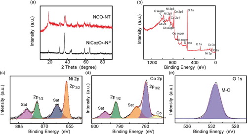
To understand the origins behind the excellent electrochemical performance of NCO-NT. Some characterization techniques are adopted to investigate NCO-NT (Figure ). In the X-ray diffraction (XRD) patterns, the NCO-NT sample has low crystallinity when compared with NiCo2O4-NF sample. It suggests that the unique NCO-NT is composed of many nanocrystals, in consistency with TEM results (Figure ). The XPS survey shows evident signals of Ni, Co and O elements in the sample. To further identify the XPS results, multiple peaks are fitted and assigned accordingly. As for the Ni–2p signal (Figure (c)), the fitting peaks could be assigned to mixed valence of 2+ and 3+. Similarly, the Co-2p signal peak could also been fitted to mixed valence of 2+ and 3+. Interestingly, Co metal signal is found in the results. The Co substance could enhance the electronic conductivity [Citation23]. It could be further verified by the EIS comparison (Figure S4). The resistance charge transfer (Rct) is reduced from 442 (pure NiCo2O4 nanofibers) to 298 (NCO-NT) ohm obviously. The remarkable rate performance especially at high current densities could be attributed to the enhanced electronic conductivity, and the hollow nanostructure inducing short ion diffusion length. This result explains the excellent rate performance in the cell assembled with NCO-NT. The O–1s signal refers to the metal–oxygen bond, indicating the co-existence of Co–O and Ni–O [Citation24,Citation25].
Figure 5. Characterization of NCO-NTs. (a) X-ray diffraction (XRD) patterns of NCO-NT and pure NiCo2O4 nfs (NiCo2O4-NF). (b) XPS survey of NCO-NT. (c–e) XPS multiple peak results of elements Ni–2p signal (c), Co-2p signal (d) and O–1s signal (e).
3.5. Microstructure of NCO-NT after cycling
The microstructure of NCO-NT after cycling is further observed by SEM. The cell after 500 cycles at 1000 mA/g is disassembled and washed by diethyl carbonate (DEC) for three times to remove the residual electrolytes. The microstructure remains well after long cycling process. In Figure S2, we could see the 1D morphology after cycling. The structure endurance during long cycling explains the excellent electrochemical performance, especially at high current densities. But the nanotubes seem to be crushed to be flat, which maybe cause the capacity decay in the long term.
4. Conclusion
In conclusion, we fabricate a NCO based nanotubes assembled with nanocrystals by a simple and reproductive phase separation method. Beneficial from the simple and special preparation method, the nanotubes are endowed with diverse physical and chemical properties. The NCO-NT displays remarkable electrochemical performance, especially for long cycling at high current density. At the current density of 100 mA/g, the specific capacity maintains 924 mAh/g after 95 cycles. At a high current density of 1000 mA/g, the NCO-NT cell exhibits stable cycling for 500 cycles. The simple and universal method opens new opportunities for fabricating hollow nanomaterials. The oxide materials synthesis could also be extended to sulfides, which is promising in Li–S and Li–O2 battery systems.
Disclosure statement
No potential conflict of interest was reported by the authors.
ORCID
Yijie Xu http://orcid.org/0000-0002-0807-8262
Additional information
Funding
References
- Whittingham MS. Lithium batteries and cathode materials. Chem Rev. 2004;104:4271–4302. doi: 10.1021/cr020731c
- Xu K. Nonaqueous liquid electrolytes for lithium-based rechargeable batteries. Chem Rev. 2004;104:4303–4418. doi: 10.1021/cr030203g
- Guo YG, Hu JS, Wan LJ. Nanostructured materials for electrochemical energy conversion and storage devices. Adv Mater. 2008;20:2878–2887. doi: 10.1002/adma.200800627
- Lin D, Liu Y, Cui Y. Reviving the lithium metal anode for high-energy batteries. Nat Nanotechnol. 2017;12:194. doi: 10.1038/nnano.2017.16
- Szczech JR, Jin S. Nanostructured silicon for high capacity lithium battery anodes. Energy Environ Sci 2011;4:56–72. doi: 10.1039/C0EE00281J
- Chan CK, Zhang XF, Cui Y. High capacity li ion battery anodes using Ge nanowires. Nano Lett. 2008;8:307–309. doi: 10.1021/nl0727157
- Chen D, Huang S, Huang R, et al. Highlights on advances in SnO2 quantum dots: Insights into synthesis strategies, modifications and applications. Mater Res Lett. 2018;6:462–488. doi: 10.1080/21663831.2018.1482837
- Poizot P, Laruelle S, Grugeon S, et al. Nano-sized transition-metal oxides as negative-electrode materials for lithium-ion batteries. Nature. 2000;407:496. doi: 10.1038/35035045
- Reddy MV, Subba Rao GV, Chowdari BVR. Metal oxides and oxysalts as anode materials for Li ion batteries. Chem Rev. 2013;113:5364–5457. doi: 10.1021/cr3001884
- Liu D, Cao G. Engineering nanostructured electrodes and fabrication of film electrodes for efficient lithium ion intercalation. Energy Environ Sci. 2010;3:1218–1237. doi: 10.1039/b922656g
- Wang Z, Zhou L, Lou XW. Metal oxide hollow nanostructures for lithium-ion batteries. Adv Mater. 2012;24:1903–1911. doi: 10.1002/adma.201200469
- Wang H-G, Yuan S, Ma D-L, et al. Electrospun materials for lithium and sodium rechargeable batteries: from structure evolution to electrochemical performance. Energy Environ Sci. 2015;8:1660–1681. doi: 10.1039/C4EE03912B
- Yan C, Chen G, Zhou X, et al. Template-based engineering of carbon-doped Co3O4 hollow nanofibers as anode materials for lithium-ion batteries. Adv Funct Mater. 2016;26:1428–1436. doi: 10.1002/adfm.201504695
- Miao Y-E, Fan W, Chen D, et al. High-performance supercapacitors based on hollow polyaniline nanofibers by electrospinning. ACS Appl Mater Interfaces. 2013;5:4423–4428. doi: 10.1021/am4008352
- Chen Y, Lu Z, Zhou L, et al. Triple-coaxial electrospun amorphous carbon nanotubes with hollow graphitic carbon nanospheres for high-performance li ion batteries. Energy Environ Sci. 2012;5:7898–7902. doi: 10.1039/c2ee22085g
- Zhang X, Aravindan V, Kumar PS, et al. Synthesis of TiO2 hollow nanofibers by co-axial electrospinning and its superior lithium storage capability in full-cell assembly with olivine phosphate. Nanoscale. 2013;5:5973–5980. doi: 10.1039/c3nr01128c
- Wang X, Li Y, Jin T, et al. Electrospun thin-walled CuCo2O4@C nanotubes as bifunctional oxygen electrocatalysts for rechargeable Zn–air batteries. Nano Lett. 2017;17:7989–7994. doi: 10.1021/acs.nanolett.7b04502
- Liu Y, Yan X, Yu Y, et al. Eco-friendly fabricated porous carbon nanofibers decorated with nanosized SnOx as high-performance lithium-ion battery anodes. ACS Sustain Chem Eng. 2016;4:2951–2959. doi: 10.1021/acssuschemeng.5b01236
- Bulemo PM, Cho H-J, Kim N-H, et al. Mesoporous SnO2 nanotubes via electrospinning–etching route: highly sensitive and selective detection of H2S molecule. ACS Appl Mater Interfaces. 2017;9:26304–26313. doi: 10.1021/acsami.7b05241
- Tang K, Yu Y, Mu X, et al. Multichannel hollow TiO2 nanofibers fabricated by single-nozzle electrospinning and their application for fast lithium storage. Electrochem Commun. 2013;28:54–57. doi: 10.1016/j.elecom.2012.12.005
- Qie L, Chen WM, Wang ZH, et al. Nitrogen-doped porous carbon nanofiber webs as anodes for lithium ion batteries with a superhigh capacity and rate capability. Adv Mater. 2012;24:2047–2050. doi: 10.1002/adma.201104634
- Chen Y, Zhu J, Qu B, et al. Graphene improving lithium-ion battery performance by construction of NiCo2O4/graphene hybrid nanosheet arrays. Nano Energy. 2014;3:88–94. doi: 10.1016/j.nanoen.2013.10.008
- Abouali S, Akbari Garakani M, Zhang B, et al. Co3O4/porous electrospun carbon nanofibers as anodes for high performance li-ion batteries. J Mater Chem A. 2014;2:16939–16944. doi: 10.1039/C4TA03206C
- Liu L, Wang J, Hou Y, et al. Self-assembled 3D foam-like NiCo2O4 as efficient catalyst for lithium oxygen batteries. Small. 2016;12:602–611. doi: 10.1002/smll.201502924
- Shen L, Che Q, Li H, et al. Mesoporous NiCo2O4 nanowire arrays grown on carbon textiles as binder-free flexible electrodes for energy storage. Adv Funct Mater. 2014;24:2630–2637. doi: 10.1002/adfm.201303138