
 ?Mathematical formulae have been encoded as MathML and are displayed in this HTML version using MathJax in order to improve their display. Uncheck the box to turn MathJax off. This feature requires Javascript. Click on a formula to zoom.
Abstract
We report on integrating ultrathin monolithic nanoporous gold (npAu) catalyst coatings for CO2 reduction in a large electrode area (25 cm2) electrochemical membrane reactor with gas diffusion electrodes at 100 mA/cm2. The CO Faraday efficiency increases with increasing thickness, from 65% to 75% and 80% for 1, 5, and 10 layers of npAu leaves where each npAu leaf layer is 100 nm thick. For the one npAu leaf layer configuration, this corresponds to an extremely high CO current density of 955 A/g gold thus demonstrating the potential for commercial applications.
GRAPHICAL ABSTRACT
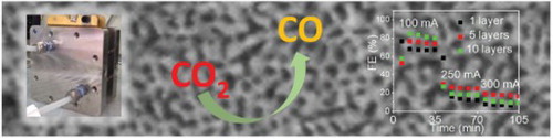
IMPACT STATEMENT
By device level optimization of catalyst integration we significantly improved the utilization of gold catalysts for electrochemical CO2 reduction to syngas at industrial relevant current densities of 100 mA/cm2.
Introduction
With rapidly decreasing prices for renewable electrical energy, electrochemical CO2 reduction (CO2R) is becoming a promising technology for generating carbon neutral fuels and chemicals [Citation1]. For example, syngas, a mixture of CO, H2, and CO2 that is used as feedstock for the Fischer–Tropsch process, can be generated by CO2R [Citation2]. CO2R also provides a pathway for high-volume seasonal energy storage by transforming the electrical energy produced by intermittent renewable energy sources, such as wind and solar, into chemical energy. However, the development and integration of scalable, low-cost, reactive, and selective electrocatalysts for these transformations remains a challenge. For the electrochemical CO2 to CO reduction, noble metal catalysts such as Au have shown good catalytic reactivity with almost 100% selectivity but require further optimization in catalysts utilization to offset the high costs of noble metal catalysts.
Nanoporous gold (npAu) has been shown to exhibit high selectivity for the CO2 to CO conversion [Citation3,Citation4]. The material is prepared by a process called dealloying, that is, selective corrosion of the less noble components of an alloy which in the case of npAu typically is Ag from a Ag-Au alloy. The low solubility (34 mM) and slow diffusion kinetics of CO2 in aqueous electrolytes [Citation5] leads to depletion of the reactant CO2 while simultaneously changing the pH value at the catalyst surface [Citation6] which together limit the achievable current density. Pushing the technology towards industrial applications requires the use of large area state-of-the-art electrochemical membrane reactors (ECMRs) with gas diffusion electrodes like those used in fuel cells. Even though the concentration of CO2 in the humidified gaseous phase is similar to that of a CO2 saturated aqueous electrolyte, the four orders of magnitude higher diffusivity of CO2 gas (16 mm2/s) compared to CO2 in aqueous solution (0.0016 mm2/s) [Citation5] effectively eliminates CO2 depletion at the catalyst surface thus opening the door to the realization of industry-relevant high current densities. For example, Jhong et al. [Citation7] demonstrated CO2R current densities of close to 100 mA/cm2 and Faradaic efficiencies (FEs) up to 95% at ∼3 V cell potential using a membraneless electrolyzer design with one square centimeter gas diffusion electrodes and a Ag catalyst loading of 0.75 mg/cm2. Not surprisingly, more and more CO2R studies are performed in gas diffusion ECMRs [Citation5,Citation8].
In the present work, we use a one-step dealloying method to integrate 100-nm-thick npAu leaf catalysts into 25 cm2 gas diffusion electrodes of a state-of-the-art zero-gap electrochemical membrane reactor (ECMR) and studied the effect of catalyst loading and integration on the CO2R performance. The zero-gap ECMR is an ideal candidate for combining high current densities with high energy efficiency as the absence of liquid electrolytes minimizes cell resistance [Citation9]. We demonstrate that the monolithic nanoporous morphology of npAu leaf catalyst enables industry-relevant current densities of 100 mA/cm2 at cell potentials as low as 2.2 V by facilitating mass and electronic transport.
Experimental
Preparation and integration of the npAu leaf catalyst
Monolithic 100-nm-thick npAu leaves (3–3/8″ × 3–3/8″) were prepared from 12 K (Au0.35Ag0.65) white gold leaf (Gold Leaf Company) by floating them on concentrated HNO3 (10 ml) in a petri dish. For 100 nm thick gold leaf, complete leaching of the Ag content (65 vol%) takes only 1 h at room temperature, leaving behind nanoporous gold with its characteristic bicontinuous ligament-pore structure with 65% porosity [Citation10]. After the dealloying process, the acid was completely but slowly exchanged against DI water. The resulting monolithic npAu leaf, still floating on top of the DI water, was rinsed for at least three more times with DI water. Next, a 25 cm2 carbon paper gas diffusion layer (GDL) (Sigracet, BC 39) was carefully inserted underneath the floating npAu leaf which was then transferred to the GDL by slowly removing the residual DI water. For higher npAu catalyst loadings multiple npAu leaves (5 or 10) were stacked on top of each other before the dealloying process. For spray coating, the npAu leaves were collected in a glass vial (20 ml) filled with DI water and broken up into a few micron wide and 100 nm thick flakes using a Sonic Dismembrator. The GDL carbon paper was then spray coated with a mixture of the resulting npAu leaf flakes with isopropyl alcohol (IPA) and ionomer.
Materials characterizations
SEM images were collected using a field-emission SEM (Jeol 7410) with lower secondary electron detector, an accelerating voltage of 5 keV and a working distance of 8 mm. The STEM images were taken with the same SEM but a different sample holder with an accelerating voltage of 30 keV.
Electrochemical CO2 reduction testing
The npAu leaf-GDL cathode assemblies were integrated into a 25 cm2 Opus 12 Inc zero-gap gas diffusion ECMR using an Orion Polymer BN2™ alkaline exchange membrane (AEM) to separate the npAu cathode-GDL assembly from the IrOx-coated porous Ti anode. The cathode-AEM-anode assembly was compressed between two flow fields against the respective cell current collectors. CO2 gas was directly fed into the cathode side of the electrolyzer at a flow rate of 250 sccm maintaining a cell pressure of 10 psi, while 0.5 M KOH was circulated via a peristaltic pump on the anode side at a rate of 60 mL/min. Electrolysis was run in constant current mode with 35-minute holds at 100, 250, and 300 mA/cm2. The as-generated gas products were detected by GC with FID and TCD detectors measuring CO and H2 yields, respectively.
Results and discussion
The npAu ligament/pore size is about 10 nm (Figure a,b) as dealloying of the ∼100-nm-thick white gold leaf takes only one hour which greatly reduces the coarsening of the structure during dealloying. As reported in previous work, the surface area of npAu with 10 nm features is ∼6 m2/g (as measured by BET and electrochemical active surface area analysis) [Citation11]. STEM micrographs were obtained by transferring the npAu leaf onto a TEM grid. The optical image of npAu leaf (Figure b, inset) demonstrates the monolithic nature of this material. The bicontinuous ligament/pore morphology of npAu is ideally suited for gas diffusion electrodes as it allows for the formation of triple phase boundaries where liquid, gas, and solid meet.
Figure 1. Microstructure of nanoporous gold leaf: (a) scanning electron microscopy (SEM) micrograph; (b) STEM image; and inset showing optical image of 100 nm thick nanoporous gold leaf showing its structural integrity. (c) Schematic diagram showing the catholyteless configuration used for electrochemical CO2 to CO reduction in the present study and photo of a 25 cm2 electrolyzer (inset).
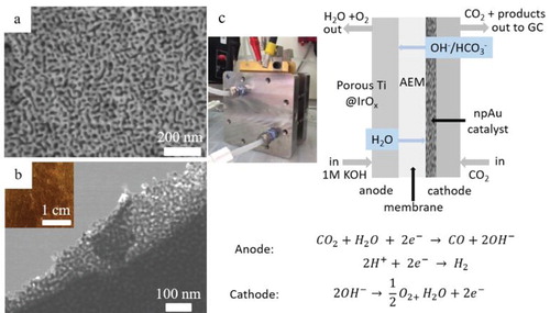
After spraying with anion ionomers, the npAu leaf-GDL assembly was tested in a commercial scale electrolyzer (Figure c inset) with a 25 cm2 electrode using a catholyteless configuration. In this work we used an anion exchange membrane as our previous CO2R catalyst performance tests with a proton exchange membrane showed an increase of the competing hydrogen evolution reaction which we attribute to the lower pH environment in this configuration [Citation9]. The same anion exchange chemistry was used for both the anion exchange membrane and the ionomer coating. In the gas-phase electrolyzer setup used in this work, gaseous CO2 diffuses through the GDL and reacts on the deposited catalyst layer with water that is brought to the cathode via diffusion through the AEM from the anolyte, thus locally forming a triple phase (gas, solid, liquid) boundary at the catalyst surface. It should be noted that the cell design (Figure c) used in this work is optimized for gas phase products and does not allow the use of a reference electrode to measure the potential of the working electrode. Instead, the overall cell voltages are reported here.
Our experiments show that the npAu leaf catalyst exhibits a good performance towards syngas production at industry-relevant current levels of 100 mA/cm2. For all current densities, the overall cell voltage increases with increasing thickness of the monolithic npAu leaf catalyst (Figure a), for example from 2.2 V for 1-layer npAu leaf to 2.8 V for 10-layer npAu leaf @ 100 mA/cm2, but remains for all thicknesses stable over the testing period (each data point corresponds to 7 min). We belief that the electrical resistance increases with increasing thickness of the monolithic npAu leaf catalyst because the likelihood of having a higher electrical contact resistance between two neighboring npAu leaf layers can be expected to increase with increasing number of layers. We believe that electron beam deposited AgAu alloy films will allow better integration of thicker npAu coatings into GDLs thus enabling a further increase in .
Figure 2. (a) The overall cell voltage. (b) Faraday efficiency for CO of three different layers of nanoporous gold. (c) CO, H2, and total FE of 1 layer of nanoporous gold leaf.
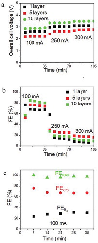
The Faradaic efficiency (FE) of the npAu leaf catalyst for CO2 to CO conversion is shown in Figure b. At 100 mA/cm2 current density, FECO increases with the increasing number of npAu leaves loaded on the GDL support, reaching 65%, 75%, and 80% for 1, 5, and 10 layers of the npAu leaf catalyst, respectively. The 10-layer npAu sample yielded the highest CO partial current density of 80 mA/cm2 and a cell potential of 2.8 V. Under these conditions, the rate of CO formation is 0.037 mol/h which corresponds to a CO2 single pass conversion efficiency of 5.2%. Accounting for hydrogen evolution, the total FE is around 100% demonstrating accurate GC calibration. At higher current densities (250 and 300 mA/cm2), the FECO decreases rapidly to less than 30% due to increased hydrogen evolution. Interestingly, the trend of increasing FECO with the increasing number of npAu leaves reverses for higher current densities, and the five-layer-thick assembly starts to outperform the 10-layer assembly.
The energy efficiency ηEE of the different npAu leaf catalysts was analyzed by comparing the energy of reactions to the input of electrical energy:
(1)
(1) where Ecell is the cell potential, z is the charge transfer number, FE are the Faradaic efficiencies, and F is the Faraday constant. Using the appropriate values for
(283 kJ/mol) and
(286 kJ/mol) for CO and H2 formation with oxygen evolution as the anode reaction, the measured Faradaic efficiencies and cell voltages reveals that the 1-layer npAu leaf catalyst has a total energy efficiency of 66% (considering CO formation only the efficiency is still 43%). While using 5- and 10-layer gold leaf catalyst coatings improves
, the energy efficiency stays constant at ∼42% (for CO only) as the gain in
(from 65% for 1-layer npAu leaf to 80% for 10-layer npAu leaf @ 100 mA/cm2) is completely compensated by the accompanying increase in cell potential (from 2.2 V for 1-layer npAu leaf to 2.8 V for 10-layer npAu leaf @ 100 mA/cm2). Considering the total energy efficiency (CO + H2), 1-layer npAu clearly outperforms 10-layer npAu leaf with 66% vs. 52%, respectively.
The 100-nm-thick npAu leaf, derived from 12 carat Ag0.65 Au0.35 alloy leaf, has a porosity of 65% resulting in a density of ∼6.8 g/cc. For a 100-nm-thick npAu film the resulting catalyst loading is thus less than 0.06 mg/cm2 resulting in a cost of ∼0.4 cts/cm2 @ a gold price of $62/g. At a current density of 100 mA/cm2 and a FE for CO2-to-CO reduction of 65%, the gravimetric current density is 955 A/g. For 10-layer npAu leaf, the FE increases by 15% while the energy efficiency stays constant due to the increase in cell potential. But the increase in materials costs with increasing catalyst layer thickness may still make economic sense if it improves catalyst stability which will be the subject of future work. For one-layer of npAu leaf, the 65% FE for CO is right in the composition range of syngas making the present study attractive to future industrial applications generating synthetic natural gas from renewable electricity and the waste product CO2. For comparison, the multi wall nanotube (MWNT)/pyridine-containing polybenzimidazole (poly[2,2′-(pyridine-2,6-diyl)bibenzimidazole-5,5′-diyl]) (PyPBI)/Au catalyst, which is currently the best Au catalyst for CO2 reduction in a gas diffusion configuration [Citation12], achieves a current density for CO of 550 A/g for the same current density. Thus, our catalyst provides a 73% improvement in gravimetric current density relative to the MWNT/PyPBI/Au catalyst. The mechanism of CO2R on Au is well documented in the literatures, [Citation3,Citation13] and we attribute the excellent performance of npAu in the current electrolyzer test configuration to its morphology and ease of integration rather than a change in the reaction mechanism. While previous tests of npAu catalysts [Citation3,Citation4,Citation14] in H-cells demonstrated high FEs for CO at low overpotentials but low current densities (30 mA/cm2 or below), the integration of npAu leaf catalysts in high current density gas diffusion electrolyzer designs is a critical step towards industrial applications. As stated above, previous work on Au catalysts reported FEs as high as 100%, but these experiments were performed in H-cells which limits the current density to a few mA/cm2 [Citation15,Citation16]. It should also be noted that the testing conditions in H- and gas diffusion cells are not identical. Therefore, the performances of catalysts can be totally different because the conditions at the solid/liquid interfaces are different during the CO2R process, for instance, pH, concentration of CO2 at catalyst surfaces, etc.
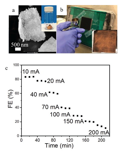
The integration of the catalyst into the electrolyzer environment is vital to its CO2R performance. As shown above, the monolithic bi-continuous Au ligament/pore morphology of npAu seems to enable high FECO at low cell potentials. As an alternative method, we tried spray coating of a GDL with a npAu leaf flake-based ink (Figure ). The spray coating process generally provides good reproducibility and uniformity [Citation7] and can easily be applied to large scale electrodes. However, this approach works best with uniform suspensions which require nanoparticles. Sonification of npAu leaf generates small, but still micron-sized npAu leaf sheets which continue to exhibit the nanoporous structure of npAu (Figure a) but are too large for preparing a uniform, stable suspension for ink jetting. We thus applied a hand spray technique for GDL coating (Figure b). The resulting catalyst coating is relatively uniform with a catalyst loading of 0.32–0.35 mg/cm2. However, the roughly four times higher catalyst loading compared to single layer npAu leaf (∼0.08 mg/cm2) did not result in an improved performance. While the FECO exceeded 80% at low current densities (10–20 mA/cm2), it rapidly decreased with increasing current densities (Figure c). At 100 mA/cm2, the FECO decreased to only 30%, less than half of the FECO of even the one-layer npAu leaf GDLs (Figure c). The five-layer npAu leaf coating, which has the same mass loading than the spray coated npAu-GDL, achieved a FECO larger than 80%. These results clearly demonstrate that the device level CO2 electrolyzer performance strongly depends on catalyst integration. An early study [Citation7] on different deposition techniques for preparing gas diffusion electrodes for CO2R supports the notion that the integration of catalysts in the GDL strongly affects its performance. Our experiments demonstrate that the monolithic npAu leaf system shows a much better performance in terms of current density, faradaic efficiency and energy efficiency than the spray coated particulate npAu leaf catalyst. The authors note that in their experience, spray-coating commercial Au nanoparticles is not a viable method for large electrode areas due to poor dispersion and thus poor coverage of the catalyst ink slurry. The present study demonstrates that nanoporous catalysts fabricated by dealloying are suitable for commercial CO2R electrolyzers. Our results also demonstrate the need for development of standardized testing protocols as the same catalyst with the same intrinsic activity can perform very differently depending on device integration.
Figure 3. Nanoporous gold leaf powders: (a) STEM image showing the representative microstructure of a npAu leaf flake. Inset in (a) shows a photo of npAu leaf powder. (b) npAu leaf ink spray coating process and the inset shows an optical image of the 25 cm2 gas diffusion electrode after coating. (c) Faraday efficiency for CO of npAu leaf ink-GDL assemblies with a npAu loading of 0.32–0.35 mg/cm2.
In summary, we have demonstrated a facile method to integrate high surface area nanoporous gold leaf catalysts with extremely low catalysts loadings of 0.08 mg/cm2 into a gas diffusion setup for effective electrochemical CO2 reduction to syngas at industrial relevant current densities of 100 mA/cm2. Maximum catalyst utilization was achieved for the one-layer npAu leaf-GDL assembly reaching a gravimetric current density of 955 A/g. We also demonstrated the importance of optimizing catalyst integration by showing that different integration of the same catalyst can dramatically change the device performance, thus underlining the need for the development of standardized testing protocols.
Acknowledgements
IM release number: LLNL-JRNL-807677. We are grateful for the nanofabrication and imaging facilities in NCEM and Molecular Foundry at Lawrence Berkeley National Laboratory.
Disclosure statement
A.K, S.H, A.L, S. M, Z. H, and K.K have financial interest in Opus 12, a company commercializing carbon dioxide electrolysis technology.
Additional information
Funding
References
- Pardal T, Messias S, Sousa M, et al. Syngas production by electrochemical CO2 reduction in an ionic liquid based-electrolyte. J CO2 Util. 2017 Mar;18:62–72.
- Kuhl KP, Cave ER, Abram DN, et al. New insights into the electrochemical reduction of carbon dioxide on metallic copper surfaces. Energy Environ Sci. 2012;5(5):7050.
- Qi Z, Biener J, Biener M. Surface oxide-derived nanoporous gold catalysts for electrochemical CO2-to-CO reduction. ACS Appl Energy Mater. 2019;2(11):7717–7721.
- Zhang WQ, He J, Liu SY, et al. Atomic origins of high electrochemical CO2 reduction efficiency on nanoporous gold. Nanoscale. 2018 May 14;10(18):8372–8376.
- Weekes DM, Salvatore DA, Reyes A, et al. Electrolytic CO2 reduction in a flow cell. Acc Chem Res. 2018 Apr;51(4):910–918.
- Raciti D, Mao M, Wang C. Mass transport modelling for the electroreduction of CO2 on Cu nanowires. Nanotechnol. 2017 Dec 21;29(4): 044001.
- Jhong HR, Brushett FR, Kenis PJA. The effects of catalyst layer deposition methodology on electrode performance. Adv Energy Mater. 2013 May;3(5):589–599.
- Jhong HR, Tornow CE, Kim C, et al. Gold nanoparticles on polymer-wrapped carbon nanotubes: an efficient and selective catalyst for the electroreduction of CO2. Chemphyschem. 2017 Nov 17;18(22):3274–3279.
- Vennekoetter JB, Sengpiel R, Wessling M. Beyond the catalyst: how electrode and reactor design determine the product spectrum during electrochemical CO2 reduction. Chem Eng J. 2019 May 15;364:89–101.
- Ding Y, Kim YJ, Erlebacher J. Nanoporous gold leaf: “ancient technology”/advanced material. Adv Mater. 2004 Nov 4;16(21):1897.
- Tan YH, Davis JA, Fujikawa K, et al. Surface area and pore size characteristics of nanoporous gold subjected to thermal, mechanical, or surface modification studied using gas adsorption isotherms, cyclic voltammetry, thermogravimetric analysis, and scanning electron microscopy (vol 22, pg 6733, 2012). J Mater Chem A. 2014 Sep 7;2(33):13749–13749.
- Verma S, Hamasaki Y, Kim C, et al. Insights into the low overpotential electroreduction of CO2 to CO on a supported gold catalyst in an alkaline flow electrolyzer. Acs Energy Lett. 2018 Jan;3(1):193–198.
- Dunwell M, Lu Q, Heyes JM, et al. The central role of bicarbonate in the electrochemical reduction of carbon dioxide on gold. J Am Chem Soc. 2017 Mar 15;139(10):3774–3783.
- Wen XS, Chang L, Gao Y, et al. A reassembled nanoporous gold leaf electrocatalyst for efficient CO2 reduction towards CO. Inorg Chem Front. 2018 May 1;5(5):1207–1212.
- Liu M, Pang YJ, Zhang B, et al. Enhanced electrocatalytic CO2 reduction via field-induced reagent concentration. Nature. 2016 Sep 15;537(7620):382.
- Li CW, Kanan MW. CO2 reduction at low overpotential on Cu electrodes resulting from the reduction of thick Cu2O films. J Am Chem Soc. 2012 May 2;134(17):7231–7234.