
Abstract
Flexible N-doped porous carbon nanofibers embedded with TiN nanoparticles are prepared for cathode materials of lithium–sulfur (Li–S) batteries. A synergistic adsorption effect of lithium polysulfides (LiPSs) can be provided by the well-dispersed TiN nanoparticles, the heteroatomic doping, and the porous nanofibers structure. As a result, the as-prepared electrode can deliver a high reversible capacity of 990 mAh g−1 after 120 cycles at 0.2 A g−1 with coulombic efficiency approaching 100%. This work provides a simple and comprehensive strategy for the preparation of high-performance Li–S batteries.
GRAPHICAL ABSTRACT

IMPACT STATEMENT
We reveal the synergistic effect of the well-dispersed TiN nanoparticles, the heteroatomic doping, and the porous nanofibers structure endows the matrix material with best adsorption capability to polysulfides.
Introduction
Lithium–sulfur (Li–S) batteries are recognized as one of the most promising candidates for next-generation large-scale energy storage systems because of their high theoretical energy density (2500 Wh kg−1) [Citation1,Citation2]. Besides, S has many advantages including low-cost and abundant [Citation3,Citation4]. However, the practical application of Li–S batteries is impeded by some problems, such as the insulating nature of S and the shuttle phenomena of lithium polysulfides (LiPSs) [Citation5,Citation6]. Strategies have been proposed to address these problems, such as infiltrating S into conductive hosts [Citation7] and optimizing the composition of electrolytes [Citation8–10]. Although those strategies are effective, the detachment of LiPSs from the cathode has not been solved successfully.
Porous carbonaceous materials could suppress the dissolution of LiPSs by physical adsorptions [Citation11], however, such adsorptions are insufficient. Heteroatom doping of carbonaceous materials can improve their adsorption capacity of LiPSs [Citation12]. Peng et al. revealed the favorable guest–host interaction at the N-doped carbon/S interface, which improved the reversibility and stability of Li–S batteries [Citation13]. In addition, polar materials (i.e. TiO2 [Citation14], TiN [Citation15,Citation16]) can trap the LiPSs on their hydrophilic surfaces. Hao et al. reported TiN, a polar material with high electrical conductivity (4000–55,000 S cm−1), could adsorb the LiPSs on their hydrophilic surfaces and catalyzed them to Li2S [Citation17]. As a result, a high capacity of 660 mAh g−1 was maintained after 200 cycles at 0.5 C. However, the electrochemical performance of Li–S batteries is still far from their theoretical performance, further development through the design of host materials still remains crucial.
Herein, we combine the physical adsorption, heteroatomic adsorption, and polar material adsorption of LiPSs into one advanced host structure of flexible N-doped porous carbon nanofibers embedded with polar TiN nanoparticles (TiN/N-PCNFs) via electrospinning. The synergistic effect of the well-dispersed TiN nanoparticles, the heteroatomic doping, and the porous nanofibers structure endows the host with excellent adsorption capability to LiPSs. After loading with S, the as-prepared electrode (S@TiN/N-PCNFs) provides excellent integrity and flexibility, which can be directly used as electrode material for Li–S batteries, limiting the use of inactive substances. The S@TiN/N-PCNFs electrode exhibits a high reversible capacity of 990 mAh g−1 after 120 cycles at 0.2 A g−1. Also, the rate performance is excellent (675 mAh g−1 at 2A g−1), which is ascribed to the TiN nanoparticles that accelerate the conversion kinetics of LiPSs by catalyticeffect.
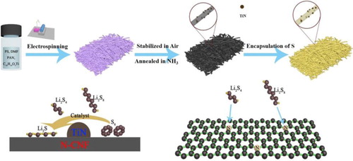
The synthesis process of S@TiN/N-PCNFs is illustrated in Figure . Firstly, the precursor solution consists of PAN, Titanium (IV) oxide bis(2,4-pentanedionate), and PS was electrospun into fibers using electrospinning technique. Subsequently, the as-collected nanofibers were stabilized in the air at 200°C, followed by annealing at 800°C in NH3 to obtain the TiN/N-PCNFs. After co-heating the mixture of TiN/N-PCNFs and S, S diffused into the pores of the TiN/N-PCNFs. The prepared S@TiN/N-PCNFs can be bent arbitrarily without any structural damage. For comparison, S loading in the N-PCNFs (S@N-PCNFs) and PCNFs (S@PCNFs) were also prepared via similar procedures.
Figure 1. Schematic illustration of the synthesis process of the S@TiN/N-PCNFs electrode, the catalyst process of the LiPSs by TiN, and the adsorption process of the LiPSs by N-doped carbon.
The as-collected fibers show a continuous and uniform fibrous structure with a diameter of about 1 μm (Figure S1A). After annealed in NH3, the fibrous morphology of the as-collected fibers is well preserved, only the diameter of the nanofibers is decreased to about 700 nm (Figure S1B), which is caused by the weight loss of the as-collected nanofibers [Citation18]. After the S infiltration process, no morphology change, and no S residues can be found on the nanofibers, indicating S is well infiltrated into the pores of TiN/N-PCNFs (Figure (A)). The transmission electron microscope (TEM) images of the S@TiN/N-PCNFs show a fibrous structure with tiny particles evenly embedded (Figure (B)). From the HRTEM images of S@TiN/N-PCNFs (Figure (C)), a clear lattice fringe of the dominated (111) crystal plane of TiN with a d-spacing of 2.45 Å can be found [Citation13]. This result confirms the formation of TiN particles in the porous nanofibers after the annealing process and the TiN particles are well preserved after co-heating with S. S@PCNFs and S@N-PCNFs exhibit similar morphologies to that of the S@TiN/N-PCNFs (Figure S3). However, no tiny particles or clear lattice fringe are observed in the samples (Figure S4).
Figure 2. (A) SEM characterization of the S@TiN/N-PCNFs. TEM (B) and HRTEM (C) images of the S@TiN/N-PCNFs. (D) XRD patterns of the prepared samples. Dark-field TEM image (E) and corresponding element mapping distribution (F-J) of the S@TiN/N-PCNFs.
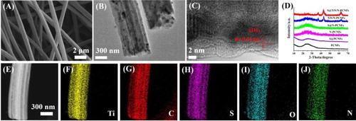
The XRD patterns of the TiN/N-PCNFs and S@TiN/N-PCNFs both exhibit the standard diffraction peaks of TiN (PDF#38-1420), which further proves the existence of TiN in the samples (Figure (D)) [Citation13]. In addition, a wide diffraction peak at 2θ = 25°, which is corresponding to the (002) diffraction of hexagonal carbon (JCPDS, card no. 75-1621) [Citation19], appears in the XRD patterns of the samples. No diffraction peaks of S can be found in the XRD patterns of the S@TiN/N-PCNFs, S@N-PCNFs, and S@PCNFs, indicating a good dispersion state of S in the samples. X-ray photoelectron spectroscopy (XPS) was used to analyze the surface chemistry of the samples. Three peaks at about 398.2, 399.9, and 401 eV can be observed in the N 1S spectrum of the S@TiN/N-PCNFs, S@N-PCNFs, and S@N-PCNFs, which are corresponding to pyridinic-N (N-6), pyrrolic-N (N-5), and graphite-N (N-Q) (Figure S5A–C) [Citation20]. The N content of the S@N-PCNFs (11.79%) is much higher than that of the S@N-PCNFs (5.26%), indicating a successful N-doping of the PCNFs after NH3 treatment. Besides, the peaks at 396.2 and 396.7 eV in the S@TiN/N-PCNFs are assigned to the Ti–N and C–N bonds. Raman spectrum further reveals the existence of Ti–N configurations in the S@TiN/N-PCNFs (Figure S6) [Citation16]. Besides, the dark-field TEM image and corresponding element mappings of the S@TiN/N-PCNFs reveal the homogenous element distribution status of S, Ti, N, C, O in the nanofiber (Figure (E–J)).
The surface area of the TiN/N-PCNFs is 142 m2 g−1, with abundant pores below 100 nm (Figure S7A–B). After co-heating with S, the surface area of the TiN/N-PCNFs decreases sharply to 6 m2 g−1, indicating the good encapsulation of S into the pores of the TiN/N-PCNFs. In the case of the N-PCNFs and PCNFs, the BET surface and pore-size distribution also decrease sharply after infiltration with S (Figure S7C–F). The contents of S in the S@TiN/N-PCNFs, S@N-PCNFs, and S@PCNFs are 63.5%, 62.9%, and 60%, respectively, which are obtained from thermogravimetry (TG) analysis (Figure S8).
Figure (A) shows the cyclic voltammogram (CV) curves of S@TiN/N-PCNFs electrode. During the lithiation process, two peaks at about 2.01 and 2.31 V can be found, which are ascribed to the conversion of S to LiPSs and LiPSs to Li2S [Citation7]. Only one peak at about 2.49 V appears in the delithiation process. The CV curves overlap relatively well after the first cycles, suggesting good cycle stability of S@TiN/N-PCNFs electrode. As a comparison, the CV curves of the S@N-PCNFs and S@PCNFs electrodes overlap worse after the first cycle, indicating poor electrochemical cycling stability (Figure S9). Besides, the reduction peaks of the S@TiN/N-PCNFs appear at higher potentials than those of the S@N-PCNFs and S@PCNFs, and the oxidation peak of the S@TiN/N-PCNFs appears at a lower potential than that of the S@N-PCNFs and S@PCNFs, indicating an improved LiPSs redox kinetics by TiN nanoparticles. Figure (B) compares the cycle performance of the prepared electrodes. For S@PCNFs electrode, only a capacity of 410 mAh g−1 is maintained after 45 cycles, suggesting a severe LiPSs dissolve and shuttle phenomena. For S@N-PCNFs electrode, a relatively higher capacity of 692 mAh g−1 is maintained after 120 cycles, indicating the positive effect of N-doping in inhibiting the dissolution and shuttle phenomena of LiPSs. For S@TiN/N-PCNFs electrode, a highest capacity of 990 mAh g−1 is maintained after 120 cycles at 0.2 A g−1, indicating the good inhibition of the dissolution and shuttle phenomena of LiPSs by N-doping and the adsorption effect of TiN nanoparticles. Figure (C) shows the shuttle current of the prepared electrodes. The S@TiN/N-PCNFs electrode exhibits the minimum shuttle current, which further proves the good inhibition effect on the dissolution of LiPSs. The visualization adsorption experiment further reveals the TiN/N-PCNFs has an excellent adsorption effect of Li2S6 (Figure S11A). The XPS of the TiN@N-PCNFs immersed in DOL/DME (1:1, v/v) solution containing 0.005 mol L−1 Li2S6 for 12 h was characterized to reveal the adsorption state between the TiN@N-PCNFs and LiPSs (Figure S11B). For the T i2p spectrum, the peaks at 455.9 and 462.4 eV are assigned to the Ti–N bond, and the peaks at 458.1 and 463.9 eV are assigned to the Ti 2p1/2 and Ti 2p2/3 [Citation21]. Besides, the peak at 456.9 eV is corresponding to the O–Ti–S bond, which confirms the strong chemisorption between the TiN@N-PCNFs andLi2S6 [Citation21].
Figure 3. (A) CV curves of S@TiN/N-PCNFs electrode at 0.2 mV s−1. (B) Cycle performance of the prepared electrodes. (C) The shuttle currents of Li–S cells with the prepared electrodes. (D) Rate performance of the prepared electrodes. (E) Long-term cycling performance of S@TiN/N-PCNFs electrode. (F) Cycle performance of S@TiN/N-PCNFs electrode with a high S areal loading.
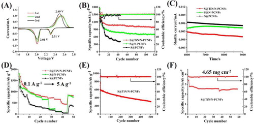
Figure (D) compares the rate performance of the prepared electrodes. The S@TiN/N-PCNFs electrode delivers a capacity as high as 882 mAh g−1, 785 mAh g−1, 722 mAh g−1, 675 mAh g−1 and 447 mAh g−1 when cycled at a current density of 0.3 A g−1, 0.5 A g−1, 1.0 A g−1, 2.0 A g−1 and 5.0 A g−1, respectively. In the case of S@N-PCNFs and S@PCNFs electrodes, much lower capacity of 120 mAh g−1 and 100 mAh g−1 are delivered at 2 A g−1, respectively. The improved kinetic process of the S@TiN/N-PCNFs electrode is due to the positive catalyst effect of TiN nanoparticles in facilitating the conversion of LiPSs [Citation15]. The lower polarization voltage of the S@TiN/N-PCNFs electrode (0.18 V) than that of the S@N-PCNFs (0.20 V) electrode and S@PCNFs (0.28 V) electrode, further confirms the catalyst effect of TiN nanoparticles (Figure S12). Besides, the lower Rct of the S@TiN/N-PCNFs electrode in electrochemical impedance spectroscopy (EIS) also proves its faster kinetic process during lithiation-delithiation (Figure S13).
Figure (E) shows the long cycle performance of the S@TiN/N-PCNFs electrode at a current density of 1.0 A g−1. After 500 cycles, the S@TiN/N-PCNFs electrode can still deliver a high capacity of 305 mAh g−1 with coulombic efficiency (CE) almost reaching 100% throughout the cycling. After the extending cycles, the structural integrity and the fibrous structure of the original S@TiN/N-PCNFs are well maintained, indicating the high stability of the electrode during cycling (Figure S14). As known, a high S areal loading is important for the practical application of Li–S batteries. The cycling performance of the S@TiN/N-PCNFs electrode with high S loading was also characterized (Figure (F)). Even with an S loading of 4.65 mg cm−2, the S@TiN/N-PCNFs electrode can still deliver a high capacity of 2.52 mAh cm−2 after 60 cycles.
Figure (A–C) shows the potentiostatic discharge curves of a Li2S8/tetraglyme solution at 2.05 V on the TiN/N-PCNFs, N-PCNFs, and PCNFs, respectively. The curves of the samples can be divided into three parts, corresponding to the reduction of Li2S8, reduction of Li2S6, and precipitation of Li2S, respectively [Citation15]. The capacity of Li2S precipitation on the TiN/N-PCNFs (151.9 mAh g−1) is higher than that of the N-PCNFs (136.8 mAh g−1) and PCNFs (119.5 mAh g−1), indicating the highest electrochemical activity of Li2S formation in the TiN/N-PCNFs. Besides, the nucleation time of Li2S on the TiN/N-PCNFs is much earlier than that on the N-PCNFs and PCNFs, indicating the highest catalytic effect for LiPSs transformation on the TiN/N-PCNFs. These results further prove that N-doping and TiN nanoparticles have a positive effect on promoting the adsorption and conversion of LiPSs, and the combination of N-doping and TiN nanoparticles into the PCNFs can maximize improve the Li2S precipitation capability.
Figure 4. The potentiostatic discharge curves of a Li2S8/tetraglyme solution at 2.05 V on the TiN/N-PCNFs (A), N-PCNFs (B), and PCNFs (C), respectively. (D) Optimized configurations for the binding of Li2Sn (n = 8, 4, 2, 1) to TiN (200) surfaces and graphene (002) surfaces.
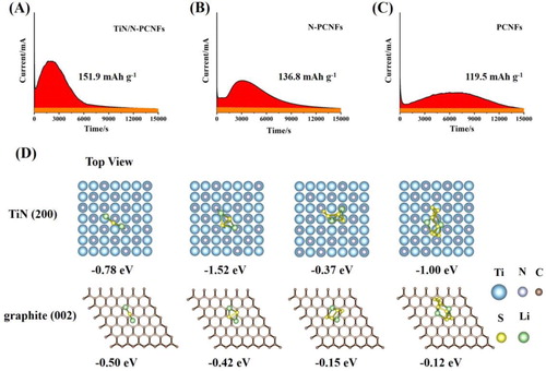
To further reveal the adsorption status of Li2Sn on TiN and carbon material, we performed density functional theory (DFT) calculations by employing the Vienna Ab-initio Simulation Package (Figure (D)). The adsorption configuration of Li2Sn on TiN (200) surfaces is presented. Based on DFT calculation, the chemical interaction between TiN (200) surfaces and Li2Sn is mainly due to two chemical bonds (Li–N and Ti–S), and the binding energy of Li2S8, Li2S4, Li2S2, and Li2S on TiN (200) surfaces are −1.00 eV, −0.37 eV, −1.52 eV and −0.78 eV, respectively. The binding energy of Li2S2 on TiN (200) surfaces is much more negative than that of Li2S8 and Li2S4, indicating TiN can catalyze the conversion from Li2S8 to Li2S2. The adsorption configuration of Li2Sn on the surface of graphene (002) surfaces is also presented. The binding energy of Li2S8, Li2S4, Li2S2 and Li2S on graphene (002) surfaces are −0.12 eV, −0.15 eV, −0.42 eV and −0.50 eV, respectively. The binding energies of Li2S8 and Li2S4 on TiN (200) surfaces are much more negative than that on graphene (002) surfaces, indicating the stronger chemical anchoring of soluble LiPSs on TiN, which greatly improves the electrochemical performance of Li–S batteries.
Conclusions
In summary, we have rationally designed an advanced cathode material for high-performance Li–S batteries, which combines the physical adsorption, heteroatomic adsorption, and polar material adsorption of lithium polysulfides (LiPSs) by integrating the free-standing flexible N-doped porous carbon nanofibers with embedded TiN nanoparticles via electrospinning. The prepared electrode exhibits excellent electrochemical performance (990 mAh g−1 after 120 cycles at 0.2 A g−1). This work provides a simple and comprehensive strategy for the preparation of high-performance Li–S batteries.
Supplemental Material
Download MS Word (3.3 MB)Acknowledgements
Zeng L and Zhu J contributed equally to this work.
Disclosure statement
No potential conflict of interest was reported by the author(s).
Additional information
Funding
References
- Bruce PG, Freunberger SA, Hardwick LJ, et al. Li-O2 and Li-S batteries with high energy storage. Nat Mater. 2012;11:19–29.
- Lin D, Liu Y, Cui Y. Reviving the lithium metal anode for high-energy batteries. Nat Nanotechnol. 2017;12:194–206.
- Seh ZW, Sun Y, Zhang Q, et al. Designing high-energy lithium-sulfur batteries. Chem Soc Rev. 2016;45:5605–5634.
- Bhargav A, He J, Gupta A, et al. Lithium-sulfur batteries: attaining the critical metrics. Joule. 2020;4:285–291.
- Manthiram A, Chung S, Zu C. Lithium-sulfur batteries: progress and prospects. Adv Mater. 2015;27:1980–2006.
- Peng H, Huang J, Cheng X, et al. Review on high-loading and high-energy lithium-sulfur batteries. Adv Energy Mater. 2017;7:1700260.
- Li Z, Jiang Y, Yuan L, et al. A highly ordered meso@microporous carbon-supported Sulfur@smaller sulfur core-shell structured cathode for Li-S batteries. ACS Nano. 2014;8:9295–9303.
- Kong L, Yin L, Xu F, et al. Electrolyte solvation chemistry for lithium-sulfur batteries with electrolyte-lean conditions. J Energy Chem. 2021;55:80–91.
- Lin Y, Huang S, Zhong L, et al. Organic liquid electrolytes in Li-S batteries: actualities and perspectives. Energy Storage Mater. 2021;34:128–147.
- Zheng J, Ji G, Fan X, et al. High-fluorinated electrolytes for Li-S batteries. Adv Energy Mater. 2019;9:1803774.
- Liang C, Dudney NJ, Howe JY. Hierarchically structured sulfur/carbon nanocomposite material for high-energy lithium battery. Chem Mater. 2009;21:4724–4730.
- Zhao X, Liu Y, Manuel J, et al. Nitrogen-doped mesoporous carbon: a top-down strategy to promote sulfur immobilization for lithium-sulfur batteries. ChemsusChem. 2015;8:3234–3241.
- Peng H, Hou T, Zhang Q, et al. Strongly coupled Interfaces between a heterogeneous carbon host and a sulfur-containing guest for highly stable lithium-sulfur batteries: mechanistic insight into capacity degradation. Adv Mater Interfaces. 2014;1:1400227.
- Yao Y, Wang H, Yang H, et al. A dual-functional conductive framework embedded with TiN-VN heterostructures for highly efficient polysulfide and lithium regulation toward Stable Li-S full batteries. Adv Mater. 2020;32:1905658.
- Li Z, He Q, Xu X, et al. A 3D nitrogen-doped graphene/TiN nanowires composite as a strong polysulfide anchor for lithium-sulfur batteries with enhanced rate performance and high areal capacity. Adv Mater. 2018;30:1804089.
- Zhou T, Lv W, Li J, et al. Twinborn TiO2-TiN heterostructures enabling smooth trapping-diffusion-conversion of polysulfides towards ultralong life lithium-sulfur batteries. Energy Environ Sci. 2017;10:1694–1703.
- Hao Z, Yuan L, Chen C, et al. Tin as a simple and efficient polysulfide immobilizer for lithium-sulfur batteries. J Mater Chem A. 2016;4:17711–17717.
- Zeng L, Zeng W, Jiang Y, et al. A flexible porous carbon nanofibers-selenium cathode with superior electrochemical performance for both Li-Se and Na-Se batteries. Adv Energy Mater. 2015;5:1401377.
- Zeng L, Wei X, Wang J, et al. Flexible one-dimensional carbon-selenium composite nanofibers with superior electrochemical performance for Li-Se/Na-Se batteries. J Power Sources. 2015;281:461–469.
- Ma M, Zhang S, Yao Y, et al. Heterostructures of 2D molybdenum dichalcogenide on 2D nitrogen-doped carbon: superior potassium-ion storage and insight into potassium storage mechanism. Adv Mater. 2020;32:2000958.
- Chen W, Jin H, Xie S, et al. Tin nanocrystal anchored on N-doped graphene as effective sulfur hosts for high-performance lithium-sulfur batteries. J Energy Chem. 2021;54:16–22.