
 ?Mathematical formulae have been encoded as MathML and are displayed in this HTML version using MathJax in order to improve their display. Uncheck the box to turn MathJax off. This feature requires Javascript. Click on a formula to zoom.
ABSTRACT
Two different types of shear bands generate in ultrafine-grained (UFG) CoCrFeMnNi high-entropy alloys deformed at 77 K, i.e. commonly-observed low angle grain boundary (LAGB) type and unusual twin-coupled type. Twin-coupled shear bands exhibit a misorientation of 56–67° with the matrix, in contrast to the LAGB shear band with a misorientation of 6–12°. Both annealing twins and deformation twins can act as precursor for twin-coupled shear bands, where dislocation accumulation along twin boundaries can tune the orientation of twin lamella. These observations suggest that twin-coupled shear bands can act as an important plastic carrier in materials deformed under extreme conditions.
IMPACT STATEMENT
Atomic structure of twin-coupled shear band is unveiled in an UFG CoCrFeMnNi HEA deformed at 77 K, which involves in dislocation-twin boundary coupled mechanism, based on delicate structural characterization via high resolution transmission electron microscopy.
1. Introduction
High-entropy alloys (HEAs) with equiatomic or near-equiatomic elements components have been extensively studied due to their attractive properties, including high strength, good thermal stability, and exceptional corrosion resistance [Citation1–4]. Among various HEAs, the face-centered cubic (FCC) CoCrFeMnNi alloy manifests an excellent combination of relatively high strength and good ductility even at cryogenic conditions [Citation5,Citation6], which is attributed to the featured twinning-induced plasticity effect [Citation7,Citation8]. Besides, shear bands have been widely recognized as an additional deformation mechanism at cryogenic temperature in metals and alloys [Citation9,Citation10]. Most shear bands in previous studies exhibit a low angle grain boundary (LAGB) configuration [Citation11,Citation12], which arises from the localized alignment of dislocations along the shear band boundary. Moreover, the simultaneous appearance of shear bands and twin lamella has been frequently reported in metallic materials with low to medium stacking fault energy, especially in samples after severe plastic deformation [Citation13,Citation14], indicating a shear band evolution mechanism coupled with deformation twins. However, the microstructural evolution of shear bands coupled with deformation twins remains largely unclear.
In this study, we investigated the shear band behavior in ultrafine-grained (UFG) CoCrFeMnNi HEA deformed at 77 K. Two types of shear bands, i.e. LAGB shear band induced by the orderly-aligned dislocations and twin-coupled shear band generated by the interaction of dislocations and twin boundaries, are observed during deformation. The twin-coupled shear bands exhibit a characteristic misorientation in the range of 56–67° with the matrix. Both annealing twins and deformation-induced twins can act as the precursor for shear band nucleation, while the intense dislocation intersections at TBs during the latter stage induce the deviation of the boundary.
2. Materials and methods
The as-cast CoCrFeMnNi HEAs ingot was homogenized at 1100°C for 2 h and then hot forged at 1000°C. A 30-mm diameter rod was obtained and subsequently cold-rolled into sheets with a thickness of ∼2.5 mm at room temperature. To achieve the fully recrystallized UFG structures, the cold-rolled sheets were annealed at 675°C for 30 min in an Ar atmosphere. The dog-bone specimens with gauge dimensions of 10 × 2 × 2.5 mm were fabricated and polished following the standard procedure for tensile tests. Cryogenic tensile tests (77 K) were performed at a strain rate of 10−3 s−1 on an Instron 5982 testing machine. Transmission electron microscope (TEM) characterization was performed on an FEI Tecnai F20 operating at 200 kV and FEI Titan G2 80–300 operating at 300 kV. The TEM foils were prepared by ion milling using a GATAN PIPS II 695 with an Ar ion source.
3. Results
The inverse pole figure map (Figure (a)) shows the uniform equiaxed grain in the recrystallized UFG CoCrFeMnNi HEA. The grain size distribution is shown in Figure (b), where an average grain size of 650 ± 150 nm was determined by a linear intercept method. The engineering and true stress–strain curves of tensile loading at 77 K show an ultra-high yield strength of 1240 ± 15 MPa and ultimate tensile strength of 1460 ± 18 MPa, with an uniform tensile elongation of 41 ± 2%. Below ϵ = 10%, the plastic deformation is mainly dominated by dislocation dynamics, as shown in our previous study [Citation7]. Here we trace the microstructural evolution under different strains at 77 K, including 20%, 30% and fractured samples (Figure (d–f)). At ϵ = 20%, dislocation multiplication and entanglement impose significant barrier for dislocation slip; instead, deformation twinning tends to be activated (Figure (d)). Specifically, the flow stress rises to 1.5 GPa, which is comparable to the critical stress of deformation twinning ∼1.35 GPa in CoCrFeMnNi HEA [Citation7]. At ϵ = 30% strain (Figure (e)), the true flow stress reaches ∼2 GPa. Such high level of flow stress cannot be accommodated by dislocation activities and deformation twins, and further deformation tends to be carried by the shear bands due to the localized ultrahigh stress concentration [Citation12].
Figure 1. Microstructure evolutions near the necking zone under different tensile strains in UFG CoCrFeMnNi HEAs at 77K. (a) Inverse pole figure map showing the equiaxed grains. (b) The distribution of grain sizes. (c) Tensile stress-strain curves of UFG HEAs at 77K. (d–f) Microstructure evolution near the necking zone and (g-i) corresponding SAED patterns for the ϵ = 20%, 30% and fractured samples. The existences of LAGB and twin-coupled shear band are indicated by the white and yellow arrows in (h) and (i), respectively.
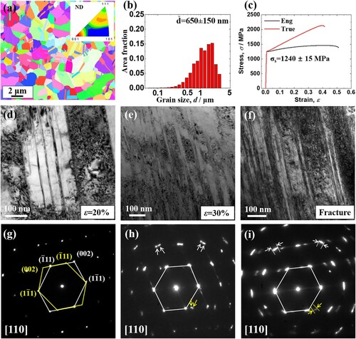
At ϵ = 30%, the diffraction spots (Figure (h)) of both matrix and twins are more diffuse than those of ϵ = 20% sample (Figure (g)), and some spots (e.g. the ones marked by white and yellow arrows in Figure (h), respectively) have split into two separate spots with a slight misorientation, which indicates the co-existence of LAGB shear bands and twin-coupled shear band. The dislocations can be trapped by twin boundaries and lead to a misorientation between the twin and the matrix [Citation15], which may result in the twin-coupled shear band in our work. Besides, the twin-coupled shear bands appear to be more prevalent in the fractured HEA sample (Figure (f,i)), as well illustrated by the slightly rotated and brighter twin diffraction spots in the corresponding SAED patterns. Therefore, a direct comparison of both microstructures and corresponding SAED patterns under ϵ = 20%, 30%, and fractured samples indicate that twin-coupled shear bands are favored under large strain in UFG HEA samples at 77 K.
Closer examinations in ϵ = 30% HEA samples confirm the co-existence of two different types of shear bands, as shown in Figures and . Figure (a) presents a bright-field TEM image of the LAGB-type shear band, which possesses a slight misorientation between the shear band and the matrix, as confirmed by the SAED patterns in Figure (b). Moreover, the diffraction spots marked by the yellow arrows in Figure (b) indicate the existence of secondary nanotwins inside the shear band. Corresponding high-resolution TEM images (Figure (d)) under [110] zone axis and fast Fourier Transform (FFT) patterns of the shear band and matrix (insets of Figure (d)) further show a slight misorientation of ∼9° between the shear band and matrix, confirming the LAGB configuration that is consistent with the common-observed shear band in previous studies [Citation11,Citation16]. Note that the shear band contains high density of transverse secondary nanotwins and stacking faults (SFs), as suggested by the dark-field TEM and HRTEM images (Figure (c,d)).
Figure 2. The LAGB shear band under 30% tensile strain in UFG HEA at 77K. (a) Bright-field TEM image of LAGB shear band, confirmed by (b) corresponding SAED patterns. The indices of shear band and matrix are indicated by blue and white lines, respectively. (c) Parallel secondary nanotwins embedded in LAGB shear band, which is confirmed by the diffraction spots marked by yellow arrows in (b). (d) HRTEM image demonstrating the boundary of the LAGB shear band with inset FFT patterns.
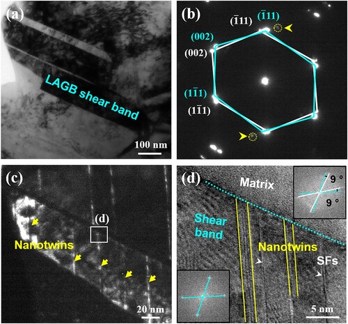
Figure 3. The twin-coupled shear band under 30% tensile strain in UFG HEA at 77K. (a) Bright-field TEM image of the deformation twin-coupled shear band. (b) The enlarged HRTEM image of the boundary of twin-coupled shear band, with corresponding FFT patterns as insets. The indices of shear band and matrix are indicated by white and blue lines, respectively. The embedded secondary nanotwins are marked by the yellow arrows. (c) The SAED patterns corresponding to (a) revealing the orientation relationship between the shear band and matrix, closed to the (d) twin relation.
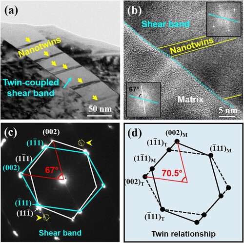
Besides the LAGB-type shear bands (Fig. S1a), twin-coupled shear bands are frequently observed in the UFG HEA samples as well (Fig. S1b). The main feature of such shear bands is the large misorientation inheriting from the crystallographic relation of twins. Figure (a) shows a twin-coupled shear band with a thickness of ∼50 nm. Some secondary nanotwins embed inside the shear band, with the thickness ranging in 4–6 nm, as indicated by the diffraction spots marked by the yellow arrows in Figure (c). Besides, the SAED pattern of twin-coupled shear bands (Figure (c)) is close to that of ideal twin structure (Figure (d)). In an ideal twin, the matrix and twin are strictly symmetric to the (11) twin boundary (TB) and the angle between crystal planes (002)M and (002)T should be 70.5° [Citation17]. However, the (002) plane of twin-coupled shear band adopts a misorientation of 67° to the corresponding (002) plane of the matrix (Figure (c)), which shows a deviation of 3.5° compared with the ideal twin structure (Figure (d)). The enlarged HRTEM image of Figure (b) shows the configurations of both sides of the shear band boundary. The atomic structure in the shear band can be clearly identified, while the structure in the matrix cannot be well imaged due to the large deviation from the ideal twin. The inset corresponding FFT patterns confirm a misorientation of 67° between the shear band and matrix, which agrees well with the SAED patterns (Figure (c)).
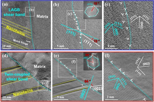
HRTEM images further reveal aligned dislocations along the boundaries of LAGB shear band and twin-coupled shear band, which results in the misorientation at shear band interfaces. Figure (a–c) and Figure (d–f) show another two examples of LAGB and twin-coupled shear bands. Figure (a) shows that dense nanotwins are embedded in LAGB-type shear band. Inset FFT pattern in Figure (b) confirms a misorientation of 12° between the shear band and the matrix, which can be regarded as the result of a sequence of dislocations re-arrangement at the boundary [Citation18,Citation19]. Dense dislocations with the Burgers vector of 1/2101. Dense dislocations with the Burgers vector of 1/2101] aligned along the boundary, coordinating the misorientation across the shear band interface (Figure (c)). This observation supports the previous viewpoint that the LAGB-type shear bands are caused by dislocation movements [Citation12,Citation20]. Similarly, the boundary of twin-coupled shear band also consists of orderly-aligned dislocations with the Burgers vectors of 1/2[101] (Figure (d–f)), which leads to the deviation from the ideal twin orientation. Specifically, the dihedral angle between (002) planes in twin-coupled shear band and matrix is 64°, showing a deviation of 6.5° compared to the ideal twin structure (with an angle of 70.5° corresponding to the (002) planes between the twin and the matrix), induced by the densely-aligned dislocations at the shear band boundary (Figure (e–f)).
Figure 4. Aligned dislocations on the boundary of (a–c) LAGB and (d–f) twin-coupled shear bands. (a) LAGB shear band with the embedded secondary nanotwins. (d) Twin-coupled shear band with the embedded secondary nanotwins.
4. Discussion
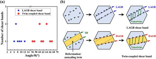
Statistical measurements in Figure show that the misorientation angles across the boundary of LAGB shear band mainly distribute in the range of 6–12°, while it is 56–67° for the twin-coupled shear band (with a deviation of 4.5–14.5° from the ideal twin structure). The formation of LAGB shear band is known as the results of the arrangement of dislocations; while, the twin-coupled shear band structure should be induced by dense dislocation-TB interactions. A previous HRTEM study has reported that dislocations can be trapped by TBs and lead to a misorientation between the twin and matrix during severe plastic deformation [Citation15]. In our experiments, deformation twins and dense dislocation slip occur simultaneously at the middle stage of cryogenic tensile test (Figure (d)). Given that TB can not only act as the effective barrier for dislocation motion but also as the accumulation site for dislocation piling-up [Citation21,Citation22], the high density of deformation twins formed during the middle stage of tensile test increases the probability of dislocation-TB interactions. As the dislocations accumulate at TBs, the TBs will gradually lose their coherency, leading to the tilt of TBs (Figure (b)). As a result, the shear bands continuously evolve with the deformation. Considering that annealing twins are common in the heat-treated samples, e.g. our UFG samples [Citation23], the dense dislocation-TB interactions can also turn a large annealing twins to a twin-coupled shear band. However, the thicknesses of annealing twin-coupled shear bands (with the typical size of hundreds of nanometers, e.g. 290 nm in Fig. S2) are much larger than that of deformation twin-coupled shear bands (with the typical size of tens of nanometers, e.g. 50 nm in Figure ), due to the significant thickness differences between the annealing and deformation twins (Fig. S3). Therefore, annealing twins should be also important precursor for the formation of twin-coupled shear bands. Compared with coarse grain, UFG materials tend to form plastic localization due to the limited strain-hardening capability in small grains, inducing premature necking with limited uniform elongation [Citation24,Citation25]. Our previous work has revealed the grain size dependence of uniform elongation in CoCrFeMnNi HEAs [Citation26], where the uniform elongation decreases with the reduction of grain size in the temperature range of 77–873 K. A reduction of uniform elongation causes an early occurrence of plastic localization corresponding to plastic instability. Secondly, the occasional small grain below the average size (Figure (b)) in UFG HEA enhances the propensity for the grains to orient themselves along the direction of maximum shear stress and the associated geometric softening triggers the shear localization and plastic instability [Citation27]. Besides, the combined large true flow stress of ∼ 2 GPa (at 30% tensile strain) and low mobility of dislocations under cryogenic temperature further facilitate the formation of shear bands by stimulating deformation twins. Further dislocation activities activated by the localized stress concentration tend to generate the shear bands. Therefore, the regions of dislocation pile-up and annealing/deformation twins might become precursors for shear band nucleation [Citation13,Citation28]. During this process, some dislocations can also transmit across the boundary, inducing secondary nanotwins inside the shear band [Citation29,Citation30]. Thus, the shear bands show a typically mixed feature of embedded nanotwins and LAGB/HAGB boundaries (Figure (b)).
Figure 5. (a) The misorientation distribution for LAGB and twin-coupled shear bands in ϵ = 30% sample. (b) Schematic illustration of the formation of LAGB and twin-coupled shear bands, respectively.
Generally, macroscopic shear bands are formed when local sites of microcosmic shear bands and the maximum shear stress are roughly aligned [Citation20]. Due to the restriction of crystallographic orientation of annealing/deformation twin, the generation of macroscopic shear bands from the twin-coupled shear bands requires much higher local stress than that from LAGB shear bands in UFG HEA. Consequently, the energy-consuming mechanism of twin-coupled shear band can delay the shear localization and improve the deformability of UFG HEAs while competing with the LAGB shear band. A supporting example is a higher elongation in UFG HEAs at 77 K than that at 273 K under tensile test [Citation7]. Deformation twins in UFG HEAs can be activated preferentially at 77 K and the twin-coupled shear band can compete with LAGB shear band to delay the plastic localization, due to its higher energy consumption.
5. Conclusion
In summary, two types of shear bands, i.e. the common-observed LAGB shear band and the unusual twin-coupled shear band are observed during the tensile test in an UFG CoCrFeMnNi HEA sample under a large strain. The twin-coupled shear bands typically exhibit a misorientation in the range of 56–67° with respect to the matrix, while the LAGB shear bands possess a misorientation of 6–12° with respect to the matrix. Both annealing twins and deformation twins can serve as precursor for twin-coupled shear bands, during which orderly-aligned dislocations along the boundaries can accommodate the misorientation between the shear band and the matrix. These findings elucidate twinning-coupled shear bands as an important plastic carrier in materials deformed under extreme conditions.
Supplemental Material
Download MS Word (2.4 MB)Disclosure statement
No potential conflict of interest was reported by the author(s).
Additional information
Funding
References
- Tsai M-H, Yeh J-W. High-entropy alloys: a critical review. Mater Res Lett. 2014;2(3):107–123.
- Zou Y. Nanomechanical studies of high-entropy alloys. J Mater Res. 2018;33(19):3035–3054.
- Yin B, Curtin WA. Origin of high strength in the CoCrFeNiPd high-entropy alloy. Mater Res Lett. 2020;8(6):209–215.
- Han L, Xu X, Li Z, et al. A novel equiaxed eutectic high-entropy alloy with excellent mechanical properties at elevated temperatures. Mater Res Lett. 2020;8(10):373–382.
- Lee S, Duarte MJ, Feuerbacher M, et al. Dislocation plasticity in FeCoCrMnNi high-entropy alloy: quantitative insights from in situ transmission electron microscopy deformation. Mater Res Lett. 2020;8(6):216–224.
- Sun SJ, Tian YZ, Lin HR, et al. Modulating the prestrain history to optimize strength and ductility in CoCrFeMnNi high-entropy alloy. Scr Mater. 2019;163:111–115.
- Sun SJ, Tian YZ, An XH, et al. Ultrahigh cryogenic strength and exceptional ductility in ultrafine-grained CoCrFeMnNi high-entropy alloy with fully recrystallized structure. Mater Today Nano. 2018;4:46–53.
- Sun SJ, Tian YZ, Lin HR, et al. Achieving high ductility in the 1.7 GPa grade CoCrFeMnNi high-entropy alloy at 77 K. Mater Sci Eng A. 2019;740-741:336–341.
- Dey SR, Hollang L, Beausir B, et al. Reprint of: shear banding in sub-microcrystalline nickel at 4K. Mech Mater. 2013;67:53–58.
- Wei Q, Kecskes LJ, Ramesh KT. Effect of low-temperature rolling on the propensity to adiabatic shear banding of commercial purity tungsten. Mater Sci Eng A. 2013;578:394–401.
- Wei Q, Jia D, Ramesh KT, et al. Evolution and microstructure of shear bands in nanostructured Fe. Appl Phys Lett. 2002;81(7):1240–1242.
- Wang J, Wang Y, Cai W, et al. Discrete shear band plasticity through dislocation activities in body-centered cubic tungsten nanowires. Sci Rep. 2018;8(1):4574.
- Miyamoto H, Vinogradov A, Hashimoto S, et al. Formation of deformation twins and related shear bands in a copper single crystal deformed by equal-channel angular pressing for one pass at room temperature. Mater Trans. 2009;50(8):1924–1929.
- Zhang K, Zheng J-H, Huang Y, et al. Evolution of twinning and shear bands in magnesium alloys during rolling at room and cryogenic temperature. Mater Des. 2020;193:108793.
- Zhang F, Feng X, Yang Z, et al. Dislocation-twin boundary interactions induced nanocrystalline via SPD processing in bulk metals. Sci Rep. 2015;5:8981.
- Xie SJ, Liaw PK, Choo H. Tensile behavior and deformation mechanisms of bulk ultrafine-grained copper. J Mater Sci. 2006;41(19):6328–6332.
- Zhu YT, Liao XZ, Wu XL. Deformation twinning in nanocrystalline materials. Prog Mater Sci. 2012;57(1):1–62.
- Zhu Q, Huang Q, Guang C, et al. Metallic nanocrystals with low angle grain boundary for controllable plastic reversibility. Nat Commun. 2020;11(1):3100.
- Sun Zeyu, Tian Xiangjun, He Bei, etal. Microstructure evolution and microhardness of the novel Al–Cu–Li-xSc alloys fabricated by laser rapid melting. Vacuum. 2021;189:110235. DOI:https://doi.org/10.1016/j.vacuum.2021.110235.
- Hsiao H-W, Li S, Dahmen KA, et al. Shear banding mechanism in compressed nanocrystalline ceramic nanopillars. Phys Rev Mater. 2019;3(8):083601.
- Lu L, Shen Y, Chen X, et al. Ultrahigh strength and high electrical conductivity in copper. Science. 2004;304(5669):422–426.
- Zhao YH, Bingert JF, Liao XZ, et al. Simultaneously increasing the ductility and strength of ultra-fine-grained pure copper. Adv Mater. 2006;18(22):2949–2953.
- Sun SJ, Tian YZ, Lin HR, et al. Enhanced strength and ductility of bulk CoCrFeMnNi high entropy alloy having fully recrystallized ultrafine-grained structure. Mater Des. 2017;133:122–127.
- Iliopoulos AC, Nikolaidis NS, Aifantis EC. Analysis of serrations and shear bands fractality in UFGs. J Mech Behav Mater. 2015;24(1-2):1–9.
- Tian YZ, Gao S, Zhao LJ, et al. Remarkable transitions of yield behavior and Lüders deformation in pure Cu by changing grain sizes. Scr Mater. 2018;142:88–91.
- Sun SJ, Tian YZ, Lin HR, et al. Temperature dependence of the Hall–Petch relationship in CoCrFeMnNi high-entropy alloy. J Alloys Compd. 2019;806:992–998.
- Jia D, Ramesh KT, Ma E. Effects of nanocrystalline and ultrafine grain sizes on constitutive behavior and shear bands in iron. Acta Mater. 2003;51(12):3495–3509.
- Li X, Zhao Q, Wang Q, et al. Shear band mediated ω phase transformation in Nb single crystals deformed at 77K. Mater Res Lett. 2021;9(12):523–530.
- Wang J, Cao G, Zhang Z, et al. Size-dependent dislocation-twin interactions. Nanoscale. 2019;11(26):12672–12679.
- Chen Y, Huang Q, Zhao S, et al. Penta-twin destruction by coordinated twin boundary deformation. Nano Lett. 2021;21(19):8378–8384.