
Abstract
Super wear-resistant absorbers are important for next-generation high-stability optical splitters. However, traditional absorbers cannot obtain ideal wear resistance because of the limitation of hardness. We show that solid solutions of transition metal carbides are new hard, low-refractive-index lossy materials (HLLM). Super wear-resistant absorbers were obtained by constructing HLLM-based optical cavities. As a proof-of-concept, the absorptance of our fabricated Ti0.93W0.07C-based optical cavity was 95.6% in 400–800 nm wavelength range. In addition, its wear resistance was 23.3 times greater than that of traditional absorbers. Through the experiments and theoretical calculations, we proposed the design principles of HLLM and presented the materials map.
IMPACT STATEMENT
We obtained the super wear-resistant absorbers for the first time through designing hard, low-refractive-index lossy materials, and constructing an optical cavity with the lossy materials as the top layer.
1. Introduction
Super wear-resistant absorbers (SWA) are functional films with high broadband absorption performance and high wear resistance. There are many applications of SWA in next-generation high-stability optical splitters devices and light-collection systems. For example, SWA is used on the surface of mechanical parts in splitters devices of optical-communication systems. It not only provides broadband absorption performance to eliminate stray light [Citation1,Citation2], but also effectively reduces the damage to the absorber caused by repeated scratches and impacts from hard objects during assembly [Citation3,Citation4]. When SWA is coated on the surface of mechanical parts of solar collectors [Citation5,Citation6], it can absorb light and resist the impact of sand particles [Citation7,Citation8]. At present, SWA has attracted much attention because of its potential applications in the civil & military industries.
The lossy optical cavities with Salisbury screen structure [Citation9–11] have both anti-reflection and high absorption loss. It is one of the most effective ways to achieve broadband absorption. Lossy optical cavities have been widely used in solar cells [Citation12], concentrated solar power [Citation13,Citation14], photodetectors [Citation15], structure color generation [Citation10,Citation16] and pyroelectric thermal detector [Citation17]. Traditionally, the loss layer is mainly made of high extinction coefficient metals such as W, Ti, Cr, etc. [Citation1,Citation15,Citation18]. However, the hardness of this kind of metal is less than 5 GPa [Citation19], and the wear resistance and scratch resistance are not good. To increase wear resistance and reduce surface reflection, researchers coated the top surface of metals with low-refractive-index oxides, such as amorphous Al2O3 and SiO2 [Citation20]. However, because the hardness of these amorphous oxides was only 8–12 GPa [Citation21], the improvement of the wear resistance of the obtained absorbers Al2O3/W/Al2O3/W was very limited [Citation22]. It is challenging to construct a lossy optical cavity for the integration of broadband absorption and super wear resistance.
In this letter, we proposed an optical cavity with Salisbury screen structure, and realized the integration of super wear resistance and broadband absorption properties for the first time. In this optical cavity, the top loss layer is no longer composed of a double-layer oxide/metal composite, but a single-layer hard, low-refractive-index lossy material (HLLM). It is called a HLLM-based optical cavity. Ti0.93W0.07C solid solution is a HLLM that has never been reported before. The absorptance of the HLLM-based optical cavity (Ti0.93W0.07C/Al2O3/W) was 95.6% in the wavelength range of 400–800 nm. The wear resistance was 23.3 times greater than that of traditional absorbers (Al2O3/W/Al2O3/W). We outline the map of HLLM candidates based on the new insight into the relationship between the microstructure of Ti0.93W0.07C solid solution and its performance. The results show that the performance of solid solutions such as Ti0.74Zr0.26C and Ti0.5Hf0.5C is better than that of Ti0.93W0.07C. Therefore, this letter provides a new way for designing SWA by introducing HLLM. This is possible to solve the bottleneck problem on the integration of super wear resistance and broadband absorption.
2. Experiments and calculations
In this work, all films were obtained by magnetron sputtering. The detailed information on sample preparation, characterization, simulation, first-principles calculations [Citation23] and structure information of optical cavity were presented in the supplementary information.
3. Results and discussion
3.1. Formation of Ti0.93W0.07C solid solution
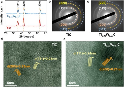
The XPS results (Section S1 of SI) show that the atomic ratio of Ti:W:C in the W-doped TiC film was 0.93:0.07:1, named Ti0.93W0.07C. In Figure (a), the (111), (200) and (220) diffraction peaks of the rock-salt phase simultaneously appear in the XRD spectra of Ti0.93W0.07C and TiC films. Compared with that of TiC, the diffraction peak of Ti0.93W0.07C film was shifted to a greater angle. These results indicate that the Ti0.93W0.07C film has the same rock-salt structure as TiC. The replacement of a large Ti atom with the atomic radius of 0.146 nm by a small W atom with the atomic radius of 0.137 nm leads lattice shrinkage. The films were studied by Selected Area Electron Diffraction (SAED) and High Resolution Transmission Electron Microscope (HRTEM) to further characterize the structure. Both Ti0.93W0.07C and TiC films show (111), (200) and (220) diffraction rings in Figure (b, c). After the introduction of W, the interplanar spacing of the (111) and (200) crystal planes of the TiC film were decreased from 0.25 and 0.23 nm to 0.24 and 0.21 nm, respectively, as shown in Figure (d, e). Therefore, the results of SAED, HRTEM and XRD are in good agreement. This proves that the Ti0.93W0.07C substitutional solid solution is formed after the introduction of W into the TiC film.
Figure 1. (a) XRD pattern of TiC and Ti0.93W0.07C films. SAED patterns of (b) TiC and (c) Ti0.93W0.07C films. HRTEM images of (d) TiC and (e) Ti0.93W0.07C films.
3.2. Design, preparation and optical performance of Ti0.93W0.07C-based optical cavity
We designed and prepared three optical cavities for the integration of high wear resistance and high broadband absorption. They are named as Ti0.93W0.07C optical cavity, TiC optical cavity and Al2O3/W optical cavity, respectively. We compared a traditional Al2O3/W optical cavity with Ti0.93W0.07C optical cavity. The theoretical absorption spectra of the three optical cavities are shown in Figure (a–c), respectively. All optical cavities show high broadband absorption.
Figure 2. Theoretical and experimental absorption spectra, electric energy density and absorbed power density of (a, d) Al2O3/W/Al2O3/W film, (b, e) TiC/Al2O3/W film and (c, f) Ti0.93W0.07C /Al2O3/W film. (g) The absorption spectrum of s-polarized and p-polarized light incident at different angles in the Ti0.93W0.07C optical cavity.
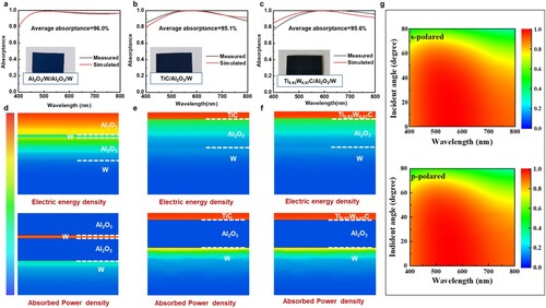
We used RF magnetron sputtering to prepare three optical cavities and characterized their optical properties to verify our designs. Because the broadband absorption of the designed optical cavities depends on the thickness of each layer, we measured the thickness of each layer for three times by a surface profiler, and showed the standard error bars of the thickness. The error is calculated in the way of ‘Mean ± S.D.’ [Citation24]. The results show that the thickness of Ti0.93W0.07C, Al2O3 and W layers in Ti0.93W0.07C optical cavity were 14.2 ± 0.1, 45.2 ± 0.1 and 152.0 ± 2.9 nm, respectively. The thickness of other optical cavities and their standard error are listed in Table S2.
In Figure (a–c), the experimental absorption spectra of the three optical cavities are consistent with the theoretical absorption spectra. This indicates that the electromagnetic simulation is completely reliable. The spectral curves of Ti0.93W0.07C and TiC optical cavity are in good agreement. This shows that the introduction of W and the formation of solid solution do not change the absorption properties of the optical cavity. In addition, although the curve shapes are slightly different, the average absorptance of Ti0.93W0.07C optical cavity (95.6%) and Al2O3/W optical cavity (96.0%) are very close. The average absorptance is the integral area of the absorption curve and the x-axis (the details are given in SI). This showed that the single-layer Ti0.93W0.07C can act as a two-layer Al2O3/W composite. It has the functions of anti-reflection and loss absorbing.
We analyzed the electric energy density and absorbed power density inside the optical cavity to explain the high broadband absorption of Ti0.93W0.07C optical cavity, as shown in Figure (d–f). In Al2O3/W optical cavity, the electric energy was concentrated on the Al2O3 layer, and absorbed power was concentrated on the W layer. This indicates that anti-reflection and loss absorbing occur in the Al2O3 and W layers, respectively. In contrast, the electric energy and absorbed power in Ti0.93W0.07C and TiC optical cavities were concentrated in the Ti0.93W0.07C and TiC layers. This indicates that Ti0.93W0.07C and TiC play the roles of anti-reflection and loss absorbing at the same time. To further explain effects of antireflection and light loss of Ti0.93W0.07C, we showed the refractive index and extinction coefficient of TiC and Ti0.93W0.07C (Figure (a,c)) from fitting the reflection spectrum. This is consistent with that from ellipsometry (Figure S5). According to the Fresnel formula [Citation25], the decrease in the refractive index of the top layer leads to the increase of absorptance (detailed in Section 5 of SI). We simulated the absorption spectra of the optical cavities with different refractive indeces to verify the assumption. The results show that the absorptance of the optical cavity increases with the increase of n3 (Figure S3). Similarly, it can be shown that the increase in k3 will also lead to the increase in absorptance. Therefore, Ti0.93W0.07C and TiC, as low refractive index loss materials, are more conducive to high broadband absorption.
Figure 3. The (a) refractive index and (c) extinction coefficient of W, Al2O3, TiC and Ti0.93W0.07C films. (b) A local structure diagram of Ti0.93W0.07C films. Green balls represent free electrons and blue balls represent localized electrons forming covalent bonds. DOS and unit cell of (d, e) Ti16C16 and (f, e) Ti15W1C16 obtained by first-principles calculations.
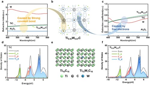
We constructed a unit cell of Ti15W1C16 (Figure (e)) for first-principles calculations to study the low refractive index and high extinction coefficient of Ti0.93W0.07C. It was the closest to Ti0.93W0.07C. The Ti16C16 unit cell was also constructed and calculated for further comparison. The density of states (DOS) of Ti15W1C16 and Ti16C16 are shown in Figure (d, f). The two spectral lines are highly consistent in shape and peak position. The result indicates that the introduction of a small amount of W does not significantly change the electronic structure of Ti16C16. This is the reason why the refractive indices and extinction coefficients of Ti15W1C16 and Ti16C16 are similar (Figure (a, c)). There is strong hybridization between the C–p orbitals and W, Ti-d orbitals from −9 eV to the Fermi level region. This indicates that there are significant covalent bond characteristics in Ti-C and W-C. The higher electron DOS near the Fermi level indicates the existence of free electrons, which are mainly from the unbonded d-orbital electrons of Ti and W. Therefore, the low refractive index of Ti0.93W0.07C is attributed to the strong covalent bond network (Figure (b)), and the extinction coefficient of Ti0.93W0.07C is attributed to the high carrier absorption (Figure (b)).
We show the absorption spectra of s-polarized and p-polarized light incident at different angles to study the angular performance of Ti0.93W0.07C optical cavity (Figure (g)). The average absorptance of Ti0.93W0.07C optical cavity was always greater than 90% as the incident angle changes from 0 to 50°. Therefore, the broadband absorption of Ti0.93W0.07C optical cavity does not strongly depend on the incident angle.
3.3. Wear resistance of Ti0.93W0.07C-based optical cavity
The SEM images of the wear track of Ti0.93W0.07C, TiC and Al2O3/W optical cavities are shown in Figure (a–c). There are many wear debris and significant ploughing grooves on the surface of the film in the SEM image of the Al2O3/W optical cavity (Figure (a)). In addition, debris in the form of tiny particles accumulated on the edge of the wear track. These phenomena are consistent with the typical abrasive wear mechanism. However, when Ti0.93W0.07C or TiC replaced Al2O3/W, only some fine ploughing grooves are shown in the wear surface. The wear surface and the edge of the track are smooth (Figure (b,c)). The wear rate of the Al2O3/W optical cavity was 174.8 × 10⁻⁹ mm3/N m, and the wear rate of the TiC optical cavity was reduced to 18.6 × 10⁻⁹ mm3/N m. The wear rate of the Ti0.93W0.07C optical cavity was further reduced to 7.2 × 10⁻⁹ mm3/N m, which was 23.3 times greater than the Al2O3/W optical cavity (Figure (a–c)). These results indicate that the replacement of Al2O3/W composite film by Ti0.93W0.07C can significantly improve the wear resistance of the optical cavity.
Figure 4. The SEM images on the wear tracks after the ball-on-disk wear tests for (a) Al2O3/W, (b) TiC and (c) Ti0.93W0.07C optical cavities. AFM images (d–f), friction coefficients curves (g) and hardness (h) for the same optical cavities. (i) The core level spectra of XPS C1s performed on the wear tracks for Ti0.93W0.07C optical cavity. (j) The WCA of Al2O3/W, TiC and Ti0.93W0.07C optical cavities.
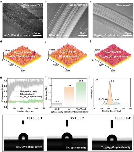
We compared the friction coefficient and hardness of the Ti0.93W0.07C optical cavity with the other optical cavities (Figure (g,h)) to explain the low wear rate of the Ti0.93W0.07C optical cavity. After the running-in period of the Al2O3/W optical cavity, the friction coefficient was about 0.90 (Figure (g)). In contrast, the friction coefficient of Ti0.93W0.07C optical cavity and TiC optical cavity were 0.23 and 0.22 after a very short running-in period. They were much lower than the friction coefficient of the Al2O3/W optical cavity. In Figure (h), the hardness of the Al2O3/W optical cavity was 15.2 GPa, the hardness of the TiC optical cavity was increased to 19.6 GPa. In addition, the hardness of the Ti0.93W0.07C optical cavity was further increased to 20.9 GPa (Figure (h)), which is greater than that of the Al2O3/W optical cavity. Therefore, the super wear resistance of the Ti0.93W0.07C optical cavity is attributed to the low friction coefficient and high hardness.
We discussed the origin of the low friction coefficient and high hardness of the Ti0.93W0.07C optical cavity in the following. The AFM images of three optical cavities are shown in Figure (d–f). The root-mean-square of surface roughness of the Ti0.93W0.07C, TiC, Al2O3 were 1.92, 1.62 and 1.74 nm, respectively. These are in good agreement with the results reported previously [Citation26,Citation27]. There are two reasons for the similar roughness. First, these films are deposited by magnetron sputtering. In the deposition process, the substrate, deposition temperature (room temperature), background vacuum (1 × 10⁻⁴Pa), sputtering gas (Argon atmosphere) and working pressure (1 Pa) are all the same. Second, these films are high-density hard materials. Previous study has shown that hard films usually have the characteristics of low surface roughness [Citation28]. Therefore, the surface roughness is not the main reason for the low friction coefficient of the Ti0.93W0.07C optical cavity. The C1s spectrum (Figure (i)) shows that the C on the surface of the Ti0.93W0.07C optical cavity after wear was mainly in the form of sp2 C–C bonds (located at 286.7 eV). It does not present in Al2O3/W. Therefore, the low friction coefficient of Ti0.93W0.07C optical cavity is related to the formation of self-lubricating graphite-like tribo-films in the top layer material Ti0.93W0.07C [Citation29–31]. The high hardness of Ti0.93W0.07C is attributed to the formation of strong covalent bonds between Ti-C and W-C, and the solid solution strengthening effect caused by the replacement of Ti by W [Citation32].
In addition, the surface wettability of the film is one of the important characteristics of the film surface. To characterize the surface wettability of the films, we tested the water contact angles (WCA, θ) of Ti0.93W0.07C, TiC and Al2O3/W optical cavities. The results show that the WCA of Ti0.93W0.07C, TiC and Al2O3/W optical cavities were 101.3°, 95.4° and 103.5°, respectively (Figure (j)). Compared with multifunctional superamphiphobic cotton fabrics [Citation33], superhydrophobic cellulose-based plastic [Citation34] and hydrophobic transparent paper [Citation35], the WCA of optical cavities was far from meeting the requirements of superhydrophobic materials for contact angles greater than 150°. Therefore, the three optical cavities have only moderate surfaces hydrophobicity.
3.4. Design criteria and material map for high-performance solid solutions
In addition to splitters devices of optical-communication systems, the wear-resistant broadband absorbers can be applied to other fields such as solar steam generation devices [Citation36]. This involves different bands and performance requirements. We provided the design principles of HLLM, and predicted candidate materials to better ‘customize’ the properties of the film.
The results show that the δ-TiC film with rock-salt structure has strong Ti-C covalent bonds and remaining d-orbital electrons. Thus, it has high hardness and extinction coefficient. Since all transition metal carbides with rock-salt structure [Citation37,Citation38], δ-TMC (TM = Ti, Zr, Hf, V, Nb, Ta, Mo, W) have similar bonding structures, they have high hardness and extinction coefficient. The hardness of δ-TMC and its average extinction coefficient in the range of 400nm–800 nm are shown in Figure (a). The hardness and extinction coefficient of amorphous dielectrics (SiO2, Al2O3) and metals (W, Cr, Ni) used in traditional absorbers are given for comparison. Amorphous dielectrics have relatively high hardness (8–12 GPa), but do not have high extinction coefficient (k ≈ 0) [Citation39]. The metals have high extinction coefficient [Citation40] (k ≈ 1.5), but do not have high hardness (0.9–5.0 GPa) [Citation19]. In contrast, δ-TMC not only has a high extinction coefficient (k ≈ 1.2), but also has a high hardness (19.8–30.2 GPa) [Citation41,Citation42]. Therefore, they are potential hard lossy materials. The refractive indexes of δ-TMC are shown in Figure (b). The refractive index of δ-HfC was as high as 2.65 [Citation43], while the refractive indexes of δ-WC [Citation44], δ-TiC and δ-TaC [Citation45] were only about 2.45. Therefore, δ-WC, δ-TiC and δ-TaC are more suitable for HLLM, which can significantly reduce the light reflection on the surface of the absorbers.
Figure 5. (a) The hardness of typical transition metal carbides, traditional dielectric materials and pure metals and their average extinction coefficient. (b) Average refractive index and extinction coefficient of typical transition metal carbides. (c) Element composition of HLLM.
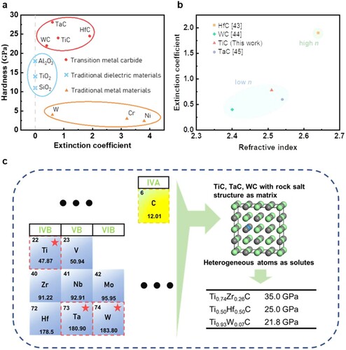
The above results show that Ti0.93W0.07C substitutional solid solution can significantly improve the wear resistance without reducing the absorption performance of the TiC matrix. Therefore, the substitutional solid solution with δ-WC, δ-TiC and δ-TaC as the matrix can obtain higher wear resistance. Previous studies [Citation46] have shown that the group-IV, -V and -VIB transition metal carbides except chromium are rock-salt structures. In addition, the atomic radii (RTM = 122–145pm) and electronegativity (χTM = 1.22–1.45) of these transition metal elements are very similar, and these three conditions are all favorable to the formation of substitutional solid solutions. Therefore, the introduction of any heterogeneous atom of Zr, Hf, V, Nb, Mo, W, Ti and Ta into the WC, TiC and TaC matrix (Figure (c)) can form a substitutional solid solution. In the literatures [Citation47,Citation48] (Figure (c)), the hardness of Ti0.74Zr0.26C and Ti0.5Hf0.5C are 35 and 25 GPa, respectively. They are greater than the hardness of Ti0.93W0.07C (21.7 GPa). Therefore, in addition to Ti0.93W0.07C solid solution, Ti0.74Zr0.26C and Ti0.5Hf0.5C are also ideal HLLMs. The optical cavities with Ti0.74Zr0.26C and Ti0.5Hf0.5C as the top loss layer have excellent performances. It is worthy of further in-depth study.
Supplemental Material
Download MS Word (318.2 KB)Acknowledgements
The authors gratefully acknowledge the financial support from the National Natural Science Foundation of China (Grant Nos. 52032004, 52002150), Fundamental Research Funds for the Central Universities (JLU), Program for JLU Science and Technology Innovative Research Team (JLUSTIRT, 2017TD-09).
Disclosure statement
No potential conflict of interest was reported by the author(s).
Additional information
Funding
References
- Shahsafi A, Joe G, Brandt S, et al. Wide-angle spectrally selective absorbers and thermal emitters based on inverse opals. ACS Photonics. 2019;6(11):2607–2611.
- Yang Z, Guo X, Lu S, et al. Investigation of stray radiation suppression in infrared imaging system using a novel broadband and high-absorption ceramic coating. Appl Sci. 2021;11(11):4952.
- Chaudhary K, Singh G, Ramkumar J, et al. Optically transparent protective coating for ITO-coated PET-based microwave metamaterial absorbers. IEEE Trans Compon Packag Manuf Technol. 2020;10(3):378–388.
- Jia H, Xu T, Yao W, et al. Fabrication and optical behavior of AuCuSi amorphous alloy film. Nanotechnology. 2021;32(33):335702.
- Gao X-H, Qiu X-L, Shen Y-Q, et al. A novel TiC–ZrB2/ZrB2/Al2O3 multilayer high temperature solar selective absorbing coating: microstructure, optical properties and failure mechanism. Sol Energy Mater Sol Cells. 2019;203:110187.
- Yang D, Zhao X, Liu Y, et al. Enhanced thermal stability of solar selective absorber based on nano-multilayered AlCrSiO films. Sol Energy Mater Sol Cells. 2020;207:110331.
- Boddupalli N, Singh G, Chandra L, et al. Dealing with dust–some challenges and solutions for enabling solar energy in desert regions. Sol Energy. 2017;150:166–176.
- Wiesinger F, San Vicente G, Fernandez-Garcia A, et al. Sandstorm erosion testing of anti-reflective glass coatings for solar energy applications. Sol Energy Mater Sol Cells. 2018;179:10–16.
- Wulan Q, He D, Zhang T, et al. Salisbury screen absorbers using epsilon-near-zero substrate. Mater Res Express. 2021;8(1):016406.
- Kats MA, Capasso F. Optical absorbers based on strong interference in ultra-thin films. Laser Photonics Rev. 2016;10(5):735–749.
- Sievenpiper DF. High-impedance electromagnetic surfaces. Los Angeles: University of California; 1999.
- Sánchez-Palencia P, García G, Conesa JC, et al. Spinel-type nitride compounds with improved features as solar cell absorbers. Acta Mater. 2020;197:316–329.
- Sani E, Failla S, Sciti D. Dark alumina for novel solar receivers. Scr Mater. 2020;176:58–62.
- Sani E, Sciti D, Capiani C, et al. Colored zirconia with high absorbance and solar selectivity. Scr Mater. 2020;186:147–151.
- Kats MA, Blanchard R, Genevet P, et al. Nanometre optical coatings based on strong interference effects in highly absorbing media. Nat Mater. 2013;12(1):20–24.
- Kats MA, Byrnes SJ, Blanchard R, et al. Enhancement of absorption and color contrast in ultra-thin highly absorbing optical coatings. Appl Phys Lett. 2013;103(10):101104.
- Stewart JW, Vella JH, Li W, et al. Ultrafast pyroelectric photodetection with on-chip spectral filters. Nat Mater. 2020;19(2):158–162.
- Ghobadi A, Hajian H, Butun B, et al. Strong light–matter interaction in lithography-free planar metamaterial perfect absorbers. ACS Photonics. 2018;5(11):4203–4221.
- Fang T-H, Chang W-J, Lin C-M, et al. Cyclic nanoindentation of semiconductor and metal thin films. Int J Mod Phys B. 2009;23(30):5639–5647.
- Chirumamilla M, Roberts AS, Ding F, et al. Multilayer tungsten-alumina-based broadband light absorbers for high-temperature applications. Opt Mater Express. 2016;6(8):2704–2714.
- Sellappan P, Rouxel T, Celarie F, et al. Composition dependence of indentation deformation and indentation cracking in glass. Acta Mater. 2013;61(16):5949–5965.
- Liu C, Liu Z, Wang B. Modification of surface morphology to enhance tribological properties for CVD coated cutting tools through wet micro-blasting post-process. Ceram Int. 2018;44(3):3430–3439.
- Jang JH, Lee C-H, Heo Y-U, et al. Stability of (Ti, M) C (M = Nb, V, Mo and W) carbide in steels using first-principles calculations. Acta Mater. 2012;60(1):208–217.
- Cumming G, Fidler F, Vaux DL. Error bars in experimental biology. J Cell Biol. 2007;177(1):7–11.
- Li Z, Butun S, Aydin K. Large-area, lithography-free super absorbers and color filters at visible frequencies using ultrathin metallic films. Acs Photonics. 2015;2(2):183–188.
- Pat S, Özen S, Şenay V, et al. A study on optical, morphological and mechanical properties of Al2O3 ultra-thin films deposited by RF reactive magnetron sputtering. Int J Surf Sci Eng. 2015;9(5):415–424.
- Olayinka A, Esther A, Philip O. Process parameters optimization to maximize surface roughness using response surface methodology of TiC thin film grown by radio frequency magnetron sputtering. Mater Today Proc. 2021;44:1221–1226.
- Chen Z, Tian W, Zhang X, et al. Effect of deposition parameters on surface roughness and consequent electromagnetic performance of capacitive RF MEMS switches: a review. J Micromech Microeng. 2017;27(11):113003.
- Ding H, Li Y, Lu J, et al. Synthesis of MAX phases Nb2CuC and Ti2 (Al0.1Cu0.9) N by A-site replacement reaction in molten salts. Mater Res Lett. 2019;7(12):510–516.
- Zhan Z, Chen Y, Radovic M, et al. Non-classical crystallographic slip in a ternary carbide–Ti2AlC. Mater Res Lett. 2020;8(7):275–281.
- Zhan Z, Radovic M, Srivastava A. On the non-classical crystallographic slip in Tin+1AlCn MAX phases. Scr Mater. 2021;194:113698.
- Esquivel J, Murdoch H, Darling K, et al. Excellent corrosion resistance and hardness in Al alloys by extended solid solubility and nanocrystalline structure. Mater Res Lett. 2018;6(1):79–83.
- Han X, Gong X. In situ, one-pot method to prepare robust superamphiphobic cotton fabrics for high buoyancy and good antifouling. ACS Appl Mater Interfaces. 2021;13(26):31298–31309.
- Wei DW, Wei H, Gauthier AC, et al. Superhydrophobic modification of cellulose and cotton textiles: methodologies and applications. J Bioresour Bioprod. 2020;5(1):1–15.
- Guan F, Song Z, Xin F, et al. Preparation of hydrophobic transparent paper via using polydimethylsiloxane as transparent agent. J Bioresour Bioprod. 2020;5(1):37–43.
- Xie J, Fan F, Chen Y, et al. Gram-scale synthesis of porous three-dimensional carbon nanosheets for high efficiency clean water production. Mater Res Lett. 2021;9(4):175–181.
- Sarker P, Harrington T, Toher C, et al. High-entropy high-hardness metal carbides discovered by entropy descriptors. Nat Commun. 2018;9(1):1–10.
- Harrington TJ, Gild J, Sarker P, et al. Phase stability and mechanical properties of novel high entropy transition metal carbides. Acta Mater. 2019;166:271–280.
- Boidin R, Halenkovič T, Nazabal V, et al. Pulsed laser deposited alumina thin films. Ceram Int. 2016;42(1):1177–1182.
- Palm KJ, Murray JB, Narayan TC, et al. Dynamic optical properties of metal hydrides. ACS Photonics. 2018;5(11):4677–4686.
- Duszová A, Halgaš R, Bľanda M, et al. Nanoindentation of WC–Co hardmetals. J Eur Ceram Soc. 2013;33(12):2227–2232.
- Gu X, Yang L, Ma X, et al. Ta addition effects on the structure, mechanical and thermal properties of sputtered Hf-Ta-C film. Ceram Int. 2019;45(12):15596–15602.
- Hans K, Latha S, Bera P, et al. Hafnium carbide based solar absorber coatings with high spectral selectivity. Sol Energy Mater Sol Cells. 2018;185:1–7.
- Gao X-H, Wang C-B, Guo Z-M, et al. Structure, optical properties and thermal stability of Al2O3-WC nanocomposite ceramic spectrally selective solar absorbers. Opt Mater. 2016;58:219–225.
- Kondaiah P, Niranjan K, John S, et al. Tantalum carbide based spectrally selective coatings for solar thermal absorber applications. Sol Energy Mater Sol Cells. 2019;198:26–34.
- Jansson U, Lewin E. Sputter deposition of transition-metal carbide films—a critical review from a chemical perspective. Thin Solid Films. 2013;536:1–24.
- de Monteynard A, Luo H, Chehimi M, et al. The structure, morphology, and mechanical properties of Ta-Hf-C coatings deposited by Pulsed direct current reactive magnetron sputtering. Coatings. 2020;10(3):212.
- Maksakova O, Pogrebnjak A, Khomenko L. editors. Composition-structure-property relations in TiZr-C nanocomposites. 2020 IEEE 10th International Conference Nanomaterials: Applications & Properties (NAP), IEEE; 2020.