
 ?Mathematical formulae have been encoded as MathML and are displayed in this HTML version using MathJax in order to improve their display. Uncheck the box to turn MathJax off. This feature requires Javascript. Click on a formula to zoom.
Abstract
This study introduced a novel magnetic-field regulation method in metallic additive manufacturing to achieve the refined grain structure and enhanced mechanical properties without post-treatment and composition changes. As a showcase material, the Ti6Al4V alloy was fabricated using direct energy deposition under the static magnetic field (SMF). It is found that the transverse SMF of 0.55 T can effectively regulate the microstructure with twisted prior-β grains (strong <001> orientation to weak <110> orientation) and discontinuous α grain boundaries. The tensile test shows a significant improvement of tensile elongation (εf) in both longitudinal and transverse directions with a slight strength decrease.
GRAPHICAL ABSTRACT

IMPACT STATEMENT
A magnetic field assisting laser additive manufacturing approach was developed to modulate the microstructure for Ti-6Al-4V alloy. The resulting refined β grains and discontinuous α grain boundaries (GBs) improve the εf significantly.
1. Introduction
Laser additive manufacturing (LAM) has been developed rapidly in recent years because of its design flexibility, high degree of freedom, low material waste, and excellent forming accuracy. Due to the localized heat input and short interaction time, the LAM is characterized by large temperature gradient (105 K m−1) and high cooling rate (103–105 K s−1) in a micro-sized molten pool [Citation1–3]. Thus, the columnar grain along the building direction (BD) becomes a typical feature in most LAM metallic materials, leading to property anisotropy. Aiming at highly comprehensive mechanical properties, a large number of studies focused on governing the solidification process and microstructure evolution of LAM components. As the optimization of processing parameters is limited, various efforts have been conducted including post-processing [Citation4–6], alloy composition re-design [Citation7,Citation8], ultrasound treatment [Citation9], or rolling treatment [Citation10,Citation11]. However, shortcomings like decreased strength, brittle inclusions, porosity, and economic issues are inevitable despite the improvements in microstructure and mechanical properties. Therefore, it is beneficial to propose a new non-contact regulation method for crystallography orientation of the β phase grains in metal additive manufacturing.
Magnetic field is used to align the crystallography orientations for ferromagnetic and non-ferromagnetic metals, based on the difference in magnetizing entropy between crystal directions [Citation12–14]. The electromagnetic field can directly affect a metals’ solidification process via the changes in phase change point, inter-dendritic flow, and solute distribution, resulting from thermoelectric magnetic (TEM) force and convection in the mushy zone. Therefore, based on high-temperature gradients, the addition of a static magnetic field (SMF) will generate an appreciable TEM force in the molten pool and mushy zone, respectively. However, the influence of the magnetic field on the microstructure and performance of the LAM process, especially the Ti6Al4V (Ti64) alloy, has been rarely reported.
2. Materials and methods
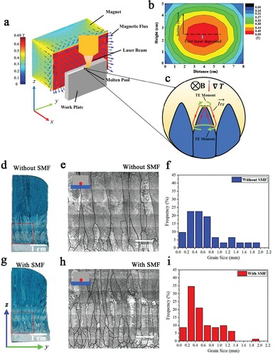
Based on our previous studies [Citation6,Citation15–17], SMF was employed to the laser-direct energy deposition (L-DED) of Ti64 alloy. The gas atomized Ti64 powders of 80–120 µm in diameter were used for an L-DED system with a 6 kW diode laser beam. The processing parameters were selected based on previous study to fabricate dense single-bead wall samples [Citation18]. The SMF system was located on both sides of the laser beam (see Figure (a,b)). The transverse magnetic intensity distribution around the substrate is shown in Figure (b). As demonstrated by the dash line, a maximum SMF of 0.55 T was imposed near the substrate. Therefore, the microstructure analysis and mechanical property test were focused on the Ti64 parts near the substrate.
Figure 1. (a) Schematic showing the solidification process of L-DED under a 0.55 T transverse SMF, where (c) the thermoelectric current and thermoelectric magnetic force are illustrated in the solidification front. (b) Distribution of magnetic field intensity. (d) and (g) OM images; (e) and (h) β grains microscopy images; (f) and (i) Histograms of β grain size.
The morphology was examined by optical microscopy (OM, DM6000, Leica). The microstructure and micro-texture were characterized by scanning electron microscopy (SEM, QUENTA 450, FEI) and electron back-scattered diffraction (EBSD). The macro-texture was measured using an X-ray diffractometer (XRD, D8 Discover, Bruker) with a Cu Kα1 on the y-z plane. The analysis of texture for EBSD and XRD were both obtained using Matlab toolbox-MTEX [Citation19]. The transmission electron microscopy (TEM, FEI Talos F200X G2) was employed to characterize the dislocations structures for as-built and after-breaking samples, respectively.
Ti64 samples were cut into flat tensile specimens along y-axis (longitudinal direction test) and z-axis (transverse direction) with a gauge length of 15 mm, a width of 2.5 mm, and a thickness of 1.5 mm. According to ASTM E8A, tensile testing was performed on three specimens at room temperature using a universal testing machine (Criterion 44, MTS) equipped with a contact extensometer with a gauge length of 12 mm on an initial strain rate of 1 mm min−1.
3. Results and discussion
Microstructural analysis reveals a substantial difference between the Ti64 samples without (Figure (d,e)) and with SMF (Figure (g,h)). The sample without SMF displays coarse columnar prior-β grains of several millimeters in length and ∼0.91 mm in width (Figure (e)). In contrast, the sample with SMF displays refined columnar prior-β grains with ∼0.57 mm in width (Figure (h)).
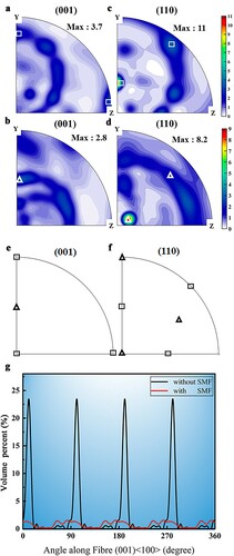
This work aims to draw a complete picture of the texture evolution in different scales of the LAM Ti64 alloy under a SMF. XRD characterization was conducted to explore the influence of SMF on the β grains’ macro-texture. As shown in Figure , in the sample without SMF, the β phase exhibits strong 001 <001> crystallographic orientation texture (Figure (a,c,g)) with maximum multiples of uniform distribution (MUD) value of 11 in (110) PFs. As shown in Figure (g), the <001> orientation of the sample without SMF is tilted by ∼13° about the BD, caused by the moving laser spot [Citation20]. In contrast, the maximum MUD value of 110 PFs is reduced to 8.2 in the presence of SMF, which indicates the decreased number of common <110> pole. The strong <001> texture is replaced by a weak <110>. The <001> orientation is tilted by ∼45° around the BD, and the <110> orientation tends to parallel the SMF direction. Therefore, SMF makes the macro-texture <001> orientation of β grains irrelevant to the moving laser beam.
Figure 2. (a) and (b) XRD 001 pole figures (PFs) of the β phase in samples without (a) and with (b) SMF. (c) and (d) XRD 110 PFs of the β phase in samples without (c) and with (d) SMF. (e) and (f) Standard poles of <100> and <110> in 001 PFs (e) and 110 PFs (f). (g) Volume percent of preferred orientations of samples without and with SMF along (001) <100> fiber texture.
As shown in Figure , SEM observation shows a basketweave-like dual-phase structure inside the β grains in the both samples (Figure (a,e)). In samples without SMF, continuous α GBs are found in the β GBs. There are ‘butterfly’ structures on both sides of the β GBs along the BD. As shown in Figure (a,b), it is the typical Widmanstätten α grain growing into adjacent β grains and also sharing the same crystal orientation with the α GBs. On the contrary, the sample with SMF exhibits discontinuous α GBs (Figure (e,f)). Meanwhile, TEM-DF (dark field) images show the typical inherent dislocation lines in the sample without SMF (Figure (d)), which is due to the localization of the thermal input during L-DED [Citation5]. However, the sample with SMF exhibited planar dislocation arrays and tends to form the sub-GBs, as shown in Figure (h) [Citation21].
As summarized in Figure , the crystallographic texture of the α phase was analyzed using EBSD. Without SMF, the α phase exhibits a clear crystallographic orientation with a maximum intensity of 38 (Figure (c)). Because of the solid-state transition of Ti64 alloy obeying Burges Orientation Relationships (BOR) (110β//0002α, <1-11>β//<2-1-10>α), the ‘butterfly’ structures share the same crystal orientations to grow into the neighbor β grains. With SMF, the maximum intensity is reduced from 38 to 25 (Figure (g)), which induced the weakened texture of α phase. As shown in Figure (g), the number of poles increased in the sample with SMF as the nucleation number of α phase increased on β GBs. Furthermore, the <0002>α of α phase is nearly parallel to the direction of SMF.
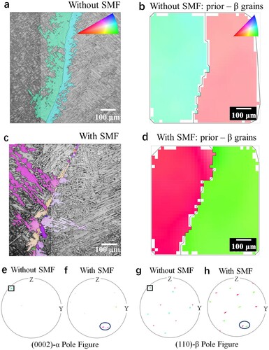
The strain–stress curves (Figure (a)) show an increased tensile elongation (εf) under SMF (as listed in Table ). The effect of SMF achieves a significant improvement in εf for longitudinal tensile tests, which was improved from 3.4 ± 0.7% to 10.8 ± 2.8%. Additionally, the εf value was slightly enhanced from 11.2 ± 1.1% to 12.6 ± 1.7% by SMF in the transverse direction. Although the UTS of samples with SMF showed a decreasing trend in both directions, the mechanical anisotropy of L-DED Ti64 was effectively avoided (Table ). Furthermore, as for the sample without SMF, the fracture surface displays typical quasi-cleavage fracture behavior (Figure (c)) on the longitudinal direction, with the fracture path along the GB α and the cracks spreading into colony α as well as transverse direction (Figure (d)). In contrast, the sample with SMF reveals a clear dimpled structure (Figure (g,h)) in both directions, as the strain–stress curves display an obvious necking of the SMF sample (Figure (a)). Figure (f,j) presents the dislocation structure for both fractured samples. The dislocation arrays were blocked inside the β grains on sample without SMF, which cannot glide through the interface of α/β phases, as shown in Figure (e,f). In contrast, the sample with SMF presents a structure of dislocation cells and dislocation walls (Figure (i,j)). Additionally, the cell interior can provide a glide for the existing mobile dislocations, which can effectively blunt localized plasticity and provide a large uniform tensile elongation[Citation5]. Therefore, the SMF has changed the size of colony α and crystallographic orientations of L-DED Ti64 alloy and resulted in higher εf.
Figure 3. Multi-scale microstructure characterizations of Ti64 sample without (a–d) and with (e–h) SMF: (a, e) SEM-BSE; (b, f) EBSD inverse pole figures (IPFs); (c, g) (0002) α PFs of α phase to corresponding (b) and (f); (d, h) TEM-DF observations.
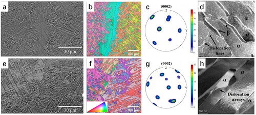
Figure 4. (a) Stress-strain curves of the samples without and with SMF performed on transverse (V*) and longitudinal (H*) directions, respectively. (b) Comparison of UTS vs. εf of Ti64 with related studies [Citation6,Citation9,Citation22–27]. (c, d and g, h) Fracture morphology of samples without and with SMF; (e, f and i, j) TEM-DF observations of the fractured longitudinal samples without (e, f) and with (i, j) SMF, which is located 1 mm below the fracture.
![Figure 4. (a) Stress-strain curves of the samples without and with SMF performed on transverse (V*) and longitudinal (H*) directions, respectively. (b) Comparison of UTS vs. εf of Ti64 with related studies [Citation6,Citation9,Citation22–27]. (c, d and g, h) Fracture morphology of samples without and with SMF; (e, f and i, j) TEM-DF observations of the fractured longitudinal samples without (e, f) and with (i, j) SMF, which is located 1 mm below the fracture.](/cms/asset/b85f408e-9e79-47c3-bd39-5d952d130c0e/tmrl_a_2064195_f0004_oc.jpg)
Table 1. Tensile behavior of L-DED Ti64 without or with SMF.
Figure (b) shows a mechanical property comparison of the single-bead wall and bulk samples fabricated by various Ti64 samples [Citation9]. Generally, it can be seen that the LAM single-bead wall samples present lower UTS than bulk samples, which can be attributed to the larger β grains (exceeding 1 mm) based on the Hall–Petch relation caused by more significant heat accumulation during thin-wall building process [Citation28]. As for as-built LAM samples (in the orange area), the parameter optimization exhibits evident limitations in improving the mechanical performance. Meanwhile, the anisotropy of LAM Ti64 is also very clearly expressed. The methods like additional elements and ultrasonic treatment can only improve the strength, whereas the post-heat-treatment can improve the εf independently. In this work, the sample of SMF achieved a balanced mechanical performance of strength and εf meeting the ASTM B381-13 (indicated by the orange dotted line) in the longitudinal direction and the UTS is slightly lower than the standard value on the transverse direction. The εf of the specimen with SMF for longitudinal direction can even be comparable with the transverse direction in Figure (b). By deploying SMF, a significant increase in εf is achieved for the as-fabricated samples in the longitudinal direction test and mechanical isotropic is effectively optimized.
The results show that the size of β grains decreased and the α grains’ crystal orientations changed by rotating β grains under the SMF. It can be attributed to the formation of TEM force in the mushy zone during L-DED under an SMF [Citation29]. The thermoelectric potential difference () (Figure ) will be activated by the Thomson–Seebeck effect during the solidification process of a metallic material, as Equation (1) [Citation30]. Therefore, the thermal current (TE,
) can be calculated by Ohm’s law (Equation (2)). When a transverse magnetic field B is applied, a unidirectional Lorentz force
(TEM force) will be produced in the vicinity of liquid/solid interface and the TEM force will act on the cellular dendrite.
(1)
(1)
(2)
(2)
(3)
(3) where σL, ∇T, B, and SL denote the electrical conductivity, temperature gradient, magnetic field intensity, and absolute thermoelectric power of the liquid phase. σL and SL are the electric conductivity and absolute thermoelectric power of the solid phase. According to Equation (3), the temperature gradient and magnetic field are the key factors for TEM force. However, the laser-based LAM process can provide a much higher temperature gradient (104–106 K m−1) in the liquid/solid interface, producing considerable TEM force under a weak magnetic field. For this case of the L-DED process, the TEM force acting on the solid part is as high as the order of 107 N m−3 according to Equation (3) and the parameters calculated by JMatPro at 1968 K [Citation31] as listed in Table . Therefore, the unidirectional TEM force acting on the cellular dendrites is strong enough to twist columnar grains in the mushy zone during the deposition process, which leads to the crystallographic orientation of the β grain changing from <001> to <110>. According to the authors’ knowledge, there are no reports about the thermoelectric force in LAM of Ti64. For the additive manufacturing process, some researchers estimated the thermoelectric force for Al-alloy and Ni-based alloy by simulation [Citation32–34]. Ti64 is a titanium alloy that solutes 6 wt.% of Al and 4 wt.% of V [Citation20]. Since the related thermoelectric properties are lack for Ti, Al-alloys are used for the estimation of TEM force in LAM process under magnetic field. Due to the relatively higher electrical conductivity of Al-alloy, the order of TEM force is 105 N m−3 [Citation32,Citation34]. As for the Ni-based alloys with similar electrical conductivity to Ti, the TEM force is at the order of 107 N m−3 [Citation33], which is consistent with the result of our calculation. TEM force-driven convection generates a stirring flow towards the liquid/solid interface, then plays the role of refining the β grains (Figure ). Moreover, the TEM force directly acts on dendrite tips and promotes their fragmentation [Citation15].
Table 2. Physical parameters of Ti-6Al-4V.
According to Equation (3), the TEM force in the mushy zone is directly controlled by the local temperature gradient and the magnetic intensity. In our case, a transverse SMF was applied to produce a unidirectional force in the front of solidification to twist the β grains. As TEM force is the production between the magnetic field intensity and the temperature gradient. The considerable TEM force can only be achieved as the temperature gradient is large enough for the LAM, whereas the SMF is only 0.55 T. For the traditional casting process, a high magnetic field of about 10 T is used to induce significant changes in microstructure. Thus, for the LAM process, the weak SMF can also result in large enough TEM forces to modify the microstructure of metal. However, SMF can also influence the solid-state phase transition [Citation35–37] and the element diffusion [Citation38,Citation39], whereas the related studies will be conducted in future work.
According to the BOR, the crystallographic orientation varies of β grain is bound to affect the subsequent phase transition of β→α. The formation of discontinuous α GBs is closely related to the texture changing of β grains. As for the reconstructed β grain of the sample without SMF, the PFs respond well with the XRD macro-texture results. These adjacent grains share a common <110>β direction (black square in Figure (e)). Hence only one α variant is produced at the β GB (black square in Figure (g)), and c-axis of α phase is parallel to the common <110> β direction, respectively, which resulted in continuous α GBs formed and low misorientation α colonies across the β GBs. In contrast, as the β grains of the sample with SMF were tilted ∼45° around the BD by TEM force, there were no α colonies across the β GBs (Figure (c)). Three variants form on the adjacent β GBs (Figure (f)) because the β grains do not have a common <110>β direction (Figure (h)) [Citation40]. More α variants can occur on the β GBs, and the discontinuous α GBs are formed in the Ti64 sample with SMF. As reported in various studies on α variants of Ti alloys, the transformed α texture is controlled by the β texture, and the common <110>β poles can cause the formation of larger and coarse α colonies during the β→α transformation [Citation40,Citation41]. As the β grains are twisted during the solidification process by TEM force, and the number of common <110>β pole is reduced, leading to the discontinuous α GBs formed and more α variants.
Figure 5. (a) and (c) EBSD IPFs of GBs α. (b) and (d) Reconstructed EBSD IPFs of β in samples. (e) and (f) 0002 PFs of the GBs α corresponding to (a) and (c). (g) and (h): 110 PFs of the reconstructed β phase corresponding to (b) and (d).
The LAM Ti64 normally has high tensile strength but low εf [Citation7,Citation24,Citation27,Citation42]. In our case, tensile loads perpendicular to the β GBs to separate adjacent β grains. However, the low εf due to the parallel lamellae α or the coarsened α colonies, especially the α colonies grow along the β GBs, which leads to the damage accumulation for early crack nucleation not only happened in LAM, but also in conventional processed Ti64 [Citation43–45]. Besides, the discontinuous α GBs can provide an improvement of 1.5 times on εf, which was also reported by Liu [Citation46]. During the tensile test, the dislocations will be trapped around the continuous α GBs and difficult for the transition, as shown in Figure (e,f), leading to stress concentration along the GBs, resulting in early crack initiation and low εf as the sample without SMF. In contrast, the dislocations can pass through the discontinuous α GBs to adjacent β grain, reducing stress concentration. Additionally, in the SMF sample, there are three α variants formed at the GBs that provide multiple activated slip systems, as shown in Figure (i,j) [Citation4]. Hence, the addition of SMF to the L-DED process effectively improves the structure of α and β phases, and thus the tensile properties of L-DED Ti64 alloy were improved.
4. Conclusion
To conclude, the transverse SMF is used to address a long-standing problem in metal LAM, namely the microstructure and texture governing of the micro-molten pool under a short interaction time. Herein, the application of SMF during the L-DED of Ti64 enables the remarkable TEM force, which induces the texture and grains size changing of the β phase and more profound impact on the formation of discontinuous α GBs. This work highlights the important role of discontinuous α GB in the εf of L-DED Ti64. Assessment of the magnetic field conditions reveals that the electromagnetic field with stronger intensity can be an important practical consideration for structural governing of large-volume LAM-fabricated components.
Disclosure statement
No potential conflict of interest was reported by the author(s).
Additional information
Funding
References
- Li XP, Ji G, Chen Z, et al. Selective laser melting of nano-TiB 2 decorated AlSi10Mg alloy with high fracture strength and ductility. Acta Mater. 2017;129:183–193.
- Yu J, Rombouts M, Maes G, et al. Material properties of Ti6Al4V parts produced by laser metal deposition. Phys Procedia. 2012;39:416–424.
- Al-Bermani SS, Blackmore ML, Zhang W, et al. The origin of microstructural diversity, texture, and mechanical properties in electron beam melted Ti-6Al-4V. Metall Mater Trans A. 2010;41:3422–3434.
- Liu C, Lu Y, Tian X, et al. Influence of continuous grain boundary α on ductility of laser melting deposited titanium alloys. Mater Sci Eng A. 2016;661:145–151.
- Zhao Z, Chen J, Tan H, et al. Achieving superior ductility for laser solid formed extra low interstitial Ti-6Al-4V titanium alloy through equiaxial alpha microstructure. Scr Mater. 2018;146:187–191.
- Wang J, Lin X, Wang M, et al. Effects of subtransus heat treatments on microstructure features and mechanical properties of wire and arc additive manufactured Ti–6Al–4V alloy. Mater Sci Eng A. 2020;776:139020.
- Narayana PL, Lee S, Choi S-W, et al. Microstructural response of β-stabilized Ti–6Al–4V manufactured by direct energy deposition. J Alloys Compd. 2019;811:152021.
- Xue A, Lin X, Wang L, et al. Influence of trace boron addition on microstructure, tensile properties and their anisotropy of Ti6Al4 V fabricated by laser directed energy deposition. Mater Des. 2019;181:107943.
- Todaro CJ, Easton MA, Qiu D, et al. Grain structure control during metal 3D printing by high-intensity ultrasound. Nat Commun. 2020;11:142. DOI:https://doi.org/10.1038/s41467-019-13874-z
- Hönnige JR, Colegrove PA, Ahmad B, et al. Residual stress and texture control in Ti-6Al-4V wire + arc additively manufactured intersections by stress relief and rolling. Mater Des. 2018;150:193–205.
- Wang Z, Liu Z, Gao C, et al. Modified wear behavior of selective laser melted Ti6Al4 V alloy by direct current assisted ultrasonic surface rolling process. Surf Coat Technol. 2020;381:125122.
- Li X, Fautrelle Y, Gagnoud A, et al. EBSD study of the influence of a high magnetic field on the microstructure and orientation of the Al-Si eutectic during directional solidification. Metall Mater Trans A. 2016;47:2952–2963.
- Liu T, Gao P-F, Dong M, et al. Effect of cooling rate on magnetostriction gradients of Tb0.27Dy0.73Fe1.95 alloys solidified in high magnetic field gradients. AIP Adv. 2016;6:056216.
- Wang Q, Liu T, Zhang C, et al. Effects of high magnetic fields on solidified structures of Mn-90.4 wt% Sb hypoeutectic alloy. Sci Technol Adv Mater. 2009;10:014606.
- Wang J, Fautrelle Y, Ren ZM, et al. Thermoelectric magnetic force acting on the solid during directional solidification under a static magnetic field. Appl Phys Lett. 2012;101:251904. DOI:https://doi.org/10.1063/1.4772510
- Li X, Zhang Y, Fautrelle Y, et al. Experimental evidence for liquid/solid interface instability caused by the stress in the solid during directional solidification under a strong magnetic field. Scr Mater. 2009;60:489–492.
- Yang J, Yu H, Yang H, et al. Prediction of microstructure in selective laser melted Ti–6Al–4V alloy by cellular automaton. J Alloys Compd. 2018;748:281–290.
- Zhao Z, Chen J, Lu X, et al. Formation mechanism of the α variant and its influence on the tensile properties of laser solid formed Ti-6Al-4V titanium alloy. Mater Sci Eng A. 2017;691:16–24.
- Bachmann F, Hielscher R, Schaeben H. Texture analysis with MTEX-free and open source software toolbox. Solid State Phenomena. 2010;160:63–68.
- Liu S, Shin YC. Additive manufacturing of Ti6Al4V alloy: a review. Mater Des. 2019;164:107552. Available from: https://www.sciencedirect.com/science/article/pii/S026412751830916X
- Le KC, Nguyen BD. Polygonization: theory and comparison with experiments. Int J Eng Sci. 2012;59:211–218.
- Wang F, Mei J, Jiang H, et al. Laser fabrication of Ti6Al4 V/TiC composites using simultaneous powder and wire feed. Mater Sci Eng A. 2007;445–446:461–466.
- Zhai Y, Galarraga H, Lados DA. Microstructure, static properties, and fatigue crack growth mechanisms in Ti-6Al-4V fabricated by additive manufacturing: LENS and EBM. Eng Fail Anal. 2016;69:3–14.
- Gou J, Wang Z, Hu S, et al. Effects of trace Nb addition on microstructure and properties of Ti–6Al–4V thin-wall structure prepared via cold metal transfer additive manufacturing. J Alloy Compound. 2020;829:154481. Available from: https://www.sciencedirect.com/science/article/pii/S0925838820308446
- Brandl E, Baufeld B, Leyens C, et al. Additive manufactured Ti-6Al-4V using welding wire: comparison of laser and arc beam deposition and evaluation with respect to aerospace material specifications. Phys Proced. 2010;5:595–606. Available from: https://www.sciencedirect.com/science/article/pii/S1875389210005134
- Brandl E, Palm F, Michailov V, et al. Mechanical properties of additive manufactured titanium (Ti–6Al–4V) blocks deposited by a solid-state laser and wire. Mater Des. 2011;32:4665–4675. Available from: https://www.sciencedirect.com/science/article/pii/S0261306911004705
- Tan H, Guo M, Clare AT, et al. Microstructure and properties of Ti-6Al-4V fabricated by low-power pulsed laser directed energy deposition. J Mater Sci Technol. 2019;35:2027–2037. Available from: https://www.sciencedirect.com/science/article/pii/S1005030219301215
- Xue A, Lin X, Wang L, et al. Heat-affected coarsening of β grain in titanium alloy during laser directed energy deposition. Scr Mater. 2021;205:114180.
- Sommerfeld A, Frank NH. The statistical theory of thermoelectric, galvano- and thermomagnetic phenomena in metals. Rev Mod Phys. 1931;3:1.
- Shercliff JA. Thermoelectric magnetohydrodynamics. Phys Fluids. 1979;22:635.
- Guo Z, Saunders N, Miodownik AP, et al. Modelling of materials properties and behaviour critical to casting simulation. Mater Sci Eng A. 2005;413–414:465–469.
- Du D, Haley JC, Dong A, et al. Influence of static magnetic field on microstructure and mechanical behavior of selective laser melted AlSi10Mg alloy. Mater Des. 2019;181:107923. Available from: https://www.sciencedirect.com/science/article/pii/S0264127519303612
- Zhu W, Yu S, Chen C, et al. Effects of static magnetic field on the microstructure of selective laser melted inconel 625 superalloy: numerical and experiment investigations. Metals. 2021;11. Available from: https://www.scopus.com/inward/record.uri?eid=2-s2.0-85119137602%26doi=10.3390%2Fmet11111846%26partnerID=40%26md5=56285be4102d383bd999311e1273ab95
- Shuai S, Lin X, Xiao W, et al. Effect of transverse static magnetic field on microstructure of Al-12%Si alloys fabricated by powder-blow additive manufacturing. Jinshu Xuebao/Acta Metallurgica Sinica. 2018;54:918–926.
- Joo HD, Choi JK, Kim SU, et al. An effect of a strong magnetic field on the phase transformation in plain carbon steels. Metall Mater Trans A. 2004;35:6. DOI:https://doi.org/10.1007/s11661-004-0075-y
- Joo HD, Kim SU, Shin NS, et al. An effect of high magnetic field on phase transformation in Fe–C system. Mater Lett. 2000;43:225–229.
- Güler E, Aktaş H. Thermally induced martensite properties in Fe–29%Ni–2%Mn alloy. Mater Lett. 2007;61:3315–3318.
- Li C, Yuan Z, Fan Y, et al. Microstructure and mechanical properties of a Ni-based superalloy after heat treatment in a steady magnetic field. J Mater Process Technol. 2017;246:176–184.
- Xuan W, Du L, Han Y, et al. Investigation on microstructure and creep properties of nickel based single crystal superalloys PWA1483 during heat treatment under an alternating magnetic field. Mater Sci Eng A. 2019;762:138087.
- Zhao ZB, Wang QJ, Hu QM, et al. Effect of β (110) texture intensity on α-variant selection and microstructure morphology during β→α phase transformation in near α titanium alloy. Acta Mater. 2017;126:372–382.
- Bhattacharyya D, Viswanathan GB, Fraser HL. Crystallographic and morphological relationships between β phase and the Widmanstätten and allotriomorphic α phase at special β grain boundaries in an α/β titanium alloy. Acta Mater. 2007;55:6765–6778.
- Gorji MB, Tancogne-Dejean T, Mohr D. Heterogeneous random medium plasticity and fracture model of additively-manufactured Ti-6Al-4V. Acta Mater. 2018;148:442–455.
- Lin JJ, Lv YH, Liu YX, et al. Microstructural evolution and mechanical properties of Ti-6Al-4V wall deposited by pulsed plasma arc additive manufacturing. Mater Des. 2016;102:30–40.
- Sauer C, Lütjering G. Influence of α layers at β grain boundaries on mechanical properties of Ti-alloys. Mater Sci Eng A. 2001;319–321:393–397.
- Carroll BE, Palmer TA, Beese AM. Anisotropic tensile behavior of Ti–6Al–4V components fabricated with directed energy deposition additive manufacturing. Acta Mater. 2015;87:309–320.
- Liu CM, Wang HM, Tian XJ, et al. Development of a pre-heat treatment for obtaining discontinuous grain boundary α in laser melting deposited Ti–5Al–5Mo–5V–1Cr–1Fe alloy. Mater Sci Eng A. 2014;604:176–182.