
Abstract
Reasonable design of a kind of non-noble metal catalyst with high catalytic performance, good stability and low cost is of great significance to realize the overall water splitting. Herein, a bottom-up method is proposed to synthesize NiFe layered double hydroxides (NiFe LDHs) coated sulfide/phosphide heterostructure on the nickel foam (Ni3S2-NixPy/NF@NiFe LDH) through hydrothermal method combined with electrodeposition. Low overpotentials of only 248 and 298 mV are required to achieve the current densities of 50 and 100 mA cm−2 for OER. Meanwhile, the HER performance only needs 137 mV at a current density of 10 mA cm−2.
GRAPHICAL ABSTRACT
1. Introduction
Hydrogen energy has attracted extensive research due to its cleanliness and stability [Citation1,Citation2]. Among them, electrocatalysis, which splits water into hydrogen without carbon emissions, is considered an ideal energy strategy for the future [Citation3]. However, electrocatalytic water splitting faces the challenge of slow kinetic reaction, which has prompted researchers to develop efficient catalysts with low dynamic overpotentials to achieve robust water splitting [Citation4–6]. At present, in the field of electrolysis of water, although precious metals and oxides such as Pt, RuO2 and IrO2 have excellent activity as catalysts for hydrogen evolution reaction (HER) or OER, these precious metals have the disadvantages of scarce resources, high prices, and poor durability [Citation7–10]. Some transition metal phosphides [Citation11–15], sulfides [Citation16–19], selenides [Citation20,Citation21], carbides [Citation22,Citation23] and oxides [Citation16,Citation24] have been reported as promising HER or OER electrocatalyst. Most of the catalysts currently studied are only active in the half-reaction of HER or OER, and very few of them are active both HER and OER under the same pH conditions [Citation25,Citation26]. Therefore, it is of great significance to find a dual-function electrocatalyst that is efficient, cheap and rich in earth resources for overall water splitting [Citation27].
Among them, Ni3S2 electrocatalyst has been extensively studied due to its high conductivity and unique structural configuration [Citation28,Citation29]. Through the hybridization of Ni3S2 with foreign active species, the use of heterogeneous interface engineering to improve the catalytic activity has been extensively studied and has made significant progress [Citation30,Citation31]. For example, Xu et al. successfully constructed a heterogeneous interface between MoS2 and NiS2 through a hydrothermal method, which further improved the catalytic water splitting performance of NiS2 [Citation32]. Meanwhile among various non-noble electrocatalysts, transition metal phosphides (TMPs) have emerged as ideal electrocatalysts for electrocatalytic water splitting [Citation11]. In the HER process, the metal and phosphorus sites of TMPs can form hydrides and capture protons. To date, TMPs including Mo-, Co-, Fe-, and Ni-phosphides have been reported to have reasonably active HER in acidic or basic solutions with considerable amounts of metal phosphorus such as Ni and Co-related Compounds also showed effective OER performance. For example, Jiao et al. successfully prepared Mo-doped Ni2P nanotube-structured catalysts for water splitting [Citation13].
On the other hand, as a kind of two-dimensional material, layered double hydroxides have attracted much attention because of their good redox activity, simple preparation and controllable composition [Citation33–35]. A large number of studies repeatedly demonstrated that LDHs materials, especially NiFe LDHs, have high OER activity [Citation36,Citation37]. The improvement of HER performance by heterojunction and the excellent OER performance of NiFe LDH itself provide us with a new idea. Here, a new type of heterogeneous 3D nano-flowers structure (Ni3S2-NixPy/NF@NiFe LDH) was successfully synthesized on the nickel foam (NF) through the hydrothermal process, phosphating treatment and electrodeposition. The Ni3S2-NixPy/NF@NiFe LDH catalyst exhibits low OER overpotentials of 248 and 298 mV at 50 and 100 mA cm−2, also showing low HER overpotential of 137 mV at 10 mA cm−2.
2. Results and discussion
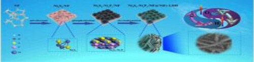
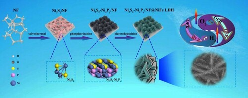
Figure schematically illustrates the synthetic process of Ni3S2-NixPy/NF@NiFe LDH catalyst. The Ni3S2-NixPy heterostructure was fabricated via a facile vulcanization and phosphating. After phosphating, the bottom-up layered Ni3S2-NixPy/NF nanoflowers with abundant heterogeneous interfaces are generated. Subsequently, the self-supported Ni3S2-NixPy/NF@NiFe LDH catalyst was synthesized by electroplating. The abundant heterogeneous interfaces between Ni3S2 and NixPy and the formation of NiFe LDH ultra-thin nanosheets might realize fast energy transfer and electron transfer. Hence, we expect that the Ni3S2-NixPy@NiFe LDH/NF electrode can display good bifunctional electrocatalytic activity to HER/OER under alkaline conditions.
Figure 1. Schematic illustration of synthesis procedures of Ni3S2-NixPy/NF@NiFe LDH catalyst.
We analyzed and confirmed the crystal phase structure of Ni3S2-NixPy/NF@NiFe LDH through XRD. As shown in Figure (a), three very strong diffraction peaks at 44.49°, 51.85° and 76.38° belongs to the NF substrate. Meanwhile, we can see that the diffraction peaks of Ni3S2-NixPy/NF@NiFe LDH are the same as those of Ni3S2 (JCPDS: 44-1418) [Citation38,Citation39]. Index to other diffraction peaks are Ni2P (JCPDS: 74-1385) and Ni12P5 (JCPDS: 74-1381). The formation of NixPy mixture (Ni2P and Ni12P5) is attributed to the polycrystalline phase of nickel-based phosphate in the compound phosphating chemistry [Citation25]. The peaks at 11.79°, 23.77°, 35.89°, 37.60°, 47.02°, 60.28° and 61.66° are the same as those of NiFe LDH (JCPDS: No.49-0188) (003), (006), (009), (104), (018), (110) and (113) planes [Citation40].
Figure 2. (a) XRD patterns of the Ni3S2-NixPy/NF@NiFe LDH and Ni3S2-NixPy/NF. (b) High-resolution of XPS profiles of Ni 2p, (c) S 2p, (d) P 2p, (e) Fe 2p and (f) O 2s.
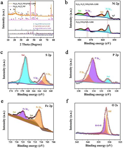
As shown in Figure S1 and Figure (b–f), investigation on the chemical states of Ni3S2-NixPy/NF@NiFe LDH is conducted by XPS. There are two main peaks at 855.8 and 873.4 eV in Figure (b), which can be distributed as Ni 2p3/2 and Ni 2p1/2 of the spin–orbit doublets of Ni2+, respectively. After phosphating, the binding energies of Ni 2p1/2 and Ni 2p3/2 display sequentially positive shifts of 0.7 and 0.6 eV, respectively. It shows that phosphating can adjust the electronic structure of Ni3S2, produce a large number of Ni3S2-NixPy heterogeneous interfaces, and cause more partial positive/negative charges (δ+/δ−). Meanwhile, there are two obvious peaks at 855.9 and 873.6 eV as satellite peaks. As shown in Figure (c), the S 2p spectrum shows a 2p1/2 peak at 163.3 eV and a 2p3/2 peak at 162.2 eV, indicating the presence of S in the catalyst. In Figure (d), the P 2p spectrum shows that the binding energies of P 2p3/2 and P 2p1/2 are 134.25 and 135.45 eV, respectively, showing the successful introduction of phosphorus after surface phosphating. Figure (e) exhibited two peaks at 727.5 and 711.9 eV corresponding to Fe 2p1/2 and Fe 2p3/2, suggesting the existence of Fe3+. The peak of O 1s at 531.35 eV can be seen in Figure (f), which is derived from the OH- after NiFe LDH electrodeposition. In Table S2, by analyzing the area occupied by the peaks of different elements in XPS, the atomic ratios can be obtained.
Figures S2, S3 and Figure (a) are the FESEM images of the Ni3S2-NixPy/NF@NiFe LDH at different stages, and thus the morphological evolution process can be disclosed. Inset Figure (a) is the enlarger part of Ni3S2-NixPy/NF@NiFe LDH, showing that the nanosheets are uniformly distributed. From the TEM image of Ni3S2-NixPy/NF@NiFe LDH (Figure (b)), we can observe flower cluster structure composed of nanosheets. The staggered arrangement of these nanosheets effectively increases the probability that the active site will provide an efficient electron transport channel.
Figure 3. Ni3S2-NixPy/NF@NiFe LDH: (a) FESEM image, (b) Low-resolution and (c) high-resolution TEM images (d) elemental mapping. (e) Microscopic schematic diagram of interface electron transfer between Ni3S2-NixPy and NiFe LDH.
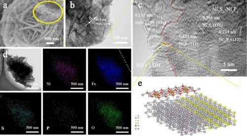
The fine structure was further revealed by HRTEM shown in Figure (c,e). The fringe spacing of 0.286 nm is attributed to the (110) plane of Ni3S2. Furthermore, the fringe spacing of 0.234 nm corresponds to the (112) characteristic plane of Ni12P5, while the lattice spacing of 0.286 nm points to the (110) plane of Ni2P. Figure (d) shows the energy spectrum distribution diagram, and the signals of Ni, Fe, O, P and S elements are distributed uniformly. Besides, the signal intensities of S and P are weaker than those of Ni, Fe and O, which displays that NiFe LDH is completely coated on the surfaces of Ni3S2-NixPy heterostructure.
We studied the HER performance of the Ni3S2-NixPy/NF@NiFe LDH and the control groups under the same conditions in Figure (a,b). The onset overpotential is calculated at current density of 1 mA cm−2. By contrast, Ni3S2-NixPy/NF@NiFe LDH displays the smallest overpotential of 134 mV at 10 mA cm−2, which is lower than other samples.
Figure 4. (a) LSV polarization curves, (b) corresponding overpotentials at 10 and 20 mA cm−2, and (c) tafel plots for OER. (d) Nyquist plots with a frequency range of 0.01–100 kHz. (e) Theoretical models for the H* adsorbed on the surface of Ni3S2 and P-Ni3S2 and (f) Gibbs free-energy diagram for H* adsorption.
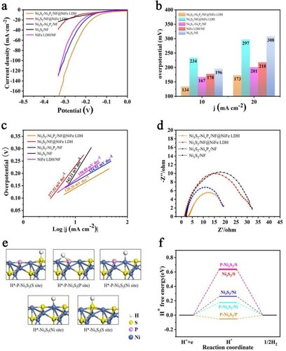
Meanwhile, the tafel slope is used to study the possible reasons for the superior performance of Ni3S2-NixPy/NF@NiFe LDH, as shown in Figure (c). The Ni3S2-NixPy/NF@NiFe LDH catalyst has the lowest tafel slope, only 120.26 mV dec−1. Significantly lower than other samples. Similarly, the impedance values are shown in the Figure (d), which can further prove that Ni3S2-NixPy/NF@NiFe LDH has the smallest charge transfer impedance and the largest electrochemical surface area.
To shed light on the effect of the constructed Ni3S2-NixPy heterostructure on the chemisorption of hydrogen and oxygen-containing intermediates, DFT calculations are performed. Considering that the Ni3S2-Ni2P is a monometallic heterostructure, we use the P doped Ni3S2 (P-Ni3S2) model to represent the Ni3S2-Ni2P interface as shown in Figure S4. The chemisorption free energies of hydrogen (ΔGH*) are first calculated to evaluate the catalytic performance for HER, and the optimized adsorption structures of H on the surface of the catalysts are depicted in Figure (e). According to Figure (f), ΔGH* of H adsorption on the Ni3S2 (S site), Ni3S2 (Ni site), P-Ni3S2 (S site) and P-Ni3S2 (Ni site) surfaces are 0.632, 0.261, 0.642 and 0.174 eV, respectively. However, ΔGH* of the P-Ni3S2 (P site) dramatically changes to −0.052 eV, which is relatively close to the ideal ΔGH* of 0 eV for the catalyst-H* state. Note that, the P site of the P-Ni3S2 model can serve as the most active sites for HER, indicating that the construction of a reasonable Ni3S2-NixPy heterostructure can successfully improve the HER performance.
We also studied the OER performance of the Ni3S2-NixPy/NF@NiFe LDH and the control groups in the same alkaline medium (1 mol L−1 of KOH).
As shown inFigure (a), after IR compensation of electrolyte resistance, we used linear sweep voltammetry (LSV) to detect its OER activity. The Ni3S2-NixPy/NF@NiFe LDH exhibits a considerable activity with only 248 and 298 mV at 50 and 100 mA cm−2 of current densities. In order to explore the contribution of NiFe LDH coating to the catalytic performance, we prepared Ni3S2-NixPy/NF catalyst. As shown in Figure (b), the catalyst requires 366 mV of overpotential at 50 mA cm−2, showing that the NiFe LDH ultra-thin nanosheets can effectively improve its OER performance. As shown in Figure (c) the calculated Tafel slopes of Ni3S2-NixPy/NF@NiFe LDH are separately 40.57 mV dec−1, which prove that Ni3S2-NixPy/NF@LDH catalyst has the highest reaction rate and fastest kinetics for water oxidation. We also compared the electrochemical impedance spectroscopy (EIS) of the catalyst materials in Figure (d). Compared with Ni3S2/NF, Ni3S2/NF@NiFe LDH and Ni3S2-NixPy/NF, Ni3S2-NixPy/NF@NiFe LDH has the lowest charge transfer resistance, indicating the fastest charge transfer. In order to further obtain the possible reasons for the excellent OER activity of Ni3S2-NixPy/NF@NiFe LDH, the electrochemically active surface area (ECSA) was measured by the double-layer capacitance (Cdl). In Figure S5a-d and Figure S6, through the CV curve of different samples we have calculated their Cdl. Ni3S2-NixPy@NiFe LDH/NF presents the largest Cdl value (45.31 mF cm−2) compared to other samples’ Cdl value. The largest Cdl value means that Ni3S2-NixPy@NiFe LDH/NF constructs more effective catalytic sites to enhance electrocatalytic performance and accelerate the catalytic kinetics, indicating that Ni3S2-NixPy/NF@NiFe LDH has the highest intrinsic activity and the most abundant catalytic sites.
Figure 5. (a) LSV polarization curves, (b) corresponding overpotentials at 50 and 100 mA cm−2 and (c) tafel plots for OER. (d) Nyquist plots with a frequency range of 0.01–100 kHz. (e) Theoretical model of P-Ni3S2@NiFe LDH heterostructure. (f) Chemisorption free energies of hydrogen (ΔEad-H) and hydroxide (ΔEad-OH).
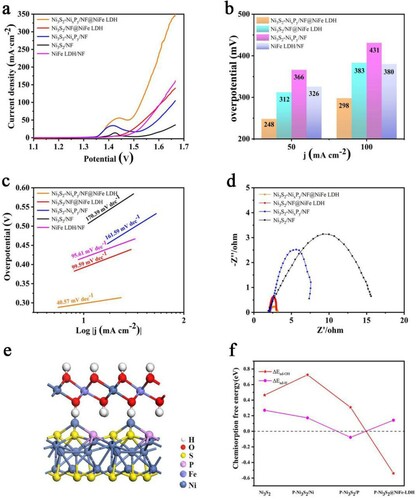
Similarly, in order to further verify the excellent OER performance of the catalyst, DFT calculation was performed. The results show that the previously constructed P doped Ni3S2 (P-Ni3S2) model has a significant improvement in the catalytic activity of HER but not that of OER. According to the results, the catalytic activity improvement for OER is not obvious, because there is a small decrease of the chemisorption free energy ΔEad-OH (0.307 eV) compared with Ni3S2 (0.465 eV). However, through Figure (a), we find that the OER performance of Ni3S3-NixPy/NF is significantly better than that of Ni2S3/NF, just showing that three-dimensional nano-flower structure has a great effect on the improvement of its catalytic performance.
Similarly, In order to further verify the influence of NiFe LDH on OER performance, DFT calculation was performed. The P-Ni3S2@NiFe LDH interface is constructed as shown in Figure (e), Figures S10 and Figure S11. We first calculate the interfacial adhesion energy between the NiFe LDH (001) surface and the P-Ni3S2 (001) surface. According to the results, the Eadhesion is −3.94 eV, which means there is a strong interaction energy between the NiFe LDH (001) surface and the P-Ni3S2 (001) surface. The chemisorption-free energies of hydrogen (ΔEad-H) and hydroxide (ΔEad-OH) on the (001) surface of Ni3S2, P-Ni3S2, and the P-Ni3S2@NiFe-LDH are shown in Figure (f). The ΔEad-H of H adsorption on the Ni3S2, P-Ni3S2 (Ni site), P-Ni3S2 (P site) and the P-Ni3S2@NiFe-LDH surfaces are 0.270, 0.172, −0.078 and 0.142 eV, respectively. The ΔEad-OH of OH adsorption is 0.465, 0.725, 0.307, and −0.539 eV respectively. It is clear that the ΔEad-H of P-Ni3S2@NiFe-LDH possesses a small increment, while ΔEad-OH shows significant decrease. Therefore, the formed interface between P-Ni3S2 and NiFe-LDH facilitates the rupture of the O-H bonds of the H2O molecule to accelerate the OER process, and the effect for HER is negligible simultaneously.
Long-term durability is also a significant parameter for evaluating the electrochemical activity. Figure S13a shows no significant degradation even after 27 h of stability test at the current densities of 50 and 10 mA cm−2, respectively, exhibiting the stable OER and HER activities. As shown in Figure S13b, after the OER cycle, the weak Ni substrate peak has completely disappeared, indicating that Ni is completely oxidized. At the same time, in Figure S13c, it can be observed that the Fe 2p orbital peak has a significant positive shift and weakens after the OER cycle, indicating that the surface Ni and Fe elements exhibit higher oxidation states [Citation20]. Then we compare and analyze the XPS of the O 2s element before and after the OER cycle in Figure S13d. The high-resolution O 1s spectrum further verified the formation of nickel monoxide after the OER process.
We used FESEM to characterize the Ni3S2-NixPy/NF@NiFe LDH electrode after 27 h OER cycles. In Figure S13e and Figure S13f, we can observe that the surface of Ni3S2-NixPy/NF@NiFe LDH after the OER cycle retains the flower-like structure and the surface becomes rougher. The high-resolution O 1s spectrum (Figure S13d) further verified the formation of NiO after the OER process [Citation25]. In Figure S9, the TEM image of Ni3S2-NixPy/NF@NiFe LDH after OER test is almost the same as before OER test. Meanwhile, as shown in Figure S13g the EDS images show the uniform dispersion of Ni, Fe, S, P and O in the Ni3S2-NixPy/NF@NiFe LDH.
Since Ni3S2-NixPy/NF@NiFe LDH has good catalytic activity for OER and HER in 1 mol L−1 of KOH solution, a two-electrode configuration was assembled by employing Ni3S2-NixPy/NF@NiFe LDH as bifunctional catalyst for overall water splitting. Meanwhile, Ni3S2-NixPy/NF@NiFe LDH || Ni3S2-NixPy/NF@NiFe LDH, Ni3S2/NF@NiFe LDH || Ni3S2/NF@NiFe LDH, Ni3S2-NixPy/NF || Ni3S2-NixPy/NF and Ni3S2/NF || Ni3S2/NF were also assembled for comparison. Figure S14a-b. manifests the assembled Ni3S2-NixPy/NF@NiFe LDH || Ni3S2-NixPy/NF@NiFe LDH couple can drive 10, 20 and 50 mA cm−2 current densities at a cell voltage of only 1.54, 1.62 and 1.82 V, respectively, which are lower than other samples.
In addition, as presented in Figure S14c and Figure S12, the calculated density of the states (DOS) of P-Ni3S2 and Ni3S2-NixPy/NF@NiFe-LDH shows that Ni3S2 doped with P and the interface between P-Ni3S2 and NiFe-LDH enhances the carrier density near the Fermi level, compared with that of pure Ni3S2, NiFe-LDH and P-Ni3S2. The higher electron density at the Fermi level leads to the higher electrical conductivity, because the elevated electron transfer helps to the enhanced electrochemical performance to accelerate the catalytic kinetics of electrochemical overall water splitting, which is consistent with the results of previous impedance tests in Figure (d) and Figure (d).
3. Conclusion
We report a novel bottom-up method to successfully construct the high-performance Ni3S2-NixPy/NF@NiFe LDH catalyst for overall water splitting. Confirmed by experimental and theoretical calculation results, the doping of P and the strong coupling interactions between P-Ni3S2 and NiFe-LDH could effectively optimize the electronic structure and chemisorption energy, synergistically boosting the HER/OER activity and stability, and significantly improving the catalytic activity. Furthermore, the assembled cell Ni3S2-NixPy/NF@NiFe LDH || Ni3S2-NixPy/NF@NiFe LDH can drive 10, 20, and 50 mA cm−2 current densities at ultralow cell voltage of only 1.54, 1.62 and 1.82 V, which are superior to the most reported catalysts. Meanwhile, the durability of the catalyst can be as long as 27 h. The Ni3S2-NixPy/NF@NiFe LDH catalyst may be a potential application candidate for efficient overall water splitting.
Supplemental Material
Download MS Word (1.6 MB)Disclosure statement
No potential conflict of interest was reported by the author(s).
Additional information
Funding
References
- Seh ZW, Kibsgaard J, Dickens CF, et al. Combining theory and experiment in electrocatalysis: insights into materials design. Science. 2017 Jan 13;355(6321). doi: https://doi.org/10.1126/science.aad4998.
- Bashyam R, Zelenay P. A class of non-precious metal composite catalysts for fuel cells. Nature. 2006 Sep 7;443(7107):63–66. doi: https://doi.org/10.1038/nature05118.
- Zhou H, Yu F, Zhu Q, et al. Water splitting by electrolysis at high current densities under 1.6 volts. Energy Environ Sci. 2018;11(10):2858–2864. doi: https://doi.org/10.1039/c8ee00927a.
- Zhang B, Lui YH, Ni H, et al. Bimetallic (FexNi1−x)2P nanoarrays as exceptionally efficient electrocatalysts for oxygen evolution in alkaline and neutral media. Nano Energy. 2017;38:553–560. doi: https://doi.org/10.1016/j.nanoen.2017.06.032.
- Wu Y, Liu Y, Li G-D, et al. Efficient electrocatalysis of overall water splitting by ultrasmall NixCo3−xS4 coupled Ni3S2 nanosheet arrays. Nano Energy. 2017;35:161–170. doi: https://doi.org/10.1016/j.nanoen.2017.03.024.
- Liu Q, Huang J, Zhao Y, et al. Tuning the coupling interface of ultrathin Ni3S2@NiV-LDH heterogeneous nanosheet electrocatalysts for improved overall water splitting. Nanoscale. 2019 May 9;11(18):8855–8863. doi: https://doi.org/10.1039/c9nr00658c.
- Lyu F, Wang Q, Choi SM, et al. Noble-metal-free electrocatalysts for oxygen evolution. Small. 2019 Jan;15(1):e1804201. doi: https://doi.org/10.1002/smll.201804201.
- Yang L, Li H, Yu Y, et al. Assembled 3D MOF on 2D nanosheets for self-boosting catalytic synthesis of N-doped carbon nanotube encapsulated metallic Co electrocatalysts for overall water splitting. Appl Catal, B. 2020;271; doi: https://doi.org/10.1016/j.apcatb.2020.118939.
- Shen F, Wang Y, Qian G, et al. Bimetallic iron-iridium alloy nanoparticles supported on nickel foam as highly efficient and stable catalyst for overall water splitting at large current density. Appl Catal, B. 2020;278; doi: https://doi.org/10.1016/j.apcatb.2020.119327.
- Wu Q, Dong A, Yang C, et al. Metal-organic framework derived Co3O4@Mo-Co3S4-Ni3S2 heterostructure supported on Ni foam for overall water splitting. Chem Eng J. 2021;413; doi: https://doi.org/10.1016/j.cej.2020.127482.
- Li Y, Zhang H, Jiang M, et al. 3D Self-supported Fe-Doped Ni2P nanosheet arrays as bifunctional catalysts for overall water splitting. Adv Funct Mater. 2017;27(37). doi: https://doi.org/10.1002/adfm.201702513.
- Wang Q, Zhao H, Li F, et al. Mo-doped Ni2P hollow nanostructures: highly efficient and durable bifunctional electrocatalysts for alkaline water splitting. J Mater Chem A. 2019;7(13):7636–7643. doi: https://doi.org/10.1039/c9ta01015g.
- Yang L, Huang L, Yao Y, et al. In-situ construction of lattice-matching NiP2/NiSe2 heterointerfaces with electron redistribution for boosting overall water splitting. Appl Catal, B. 2021;282; doi: https://doi.org/10.1016/j.apcatb.2020.119584.
- Marquez-Montes RA, Kawashima K, Son YJ, et al. Mass transport-enhanced electrodeposition of Ni–S–P–O films on nickel foam for electrochemical water splitting. J Mater Chem A. 2021;9(12):7736–7749. doi: https://doi.org/10.1039/d0ta12097a.
- Hu H-S, Li Y, Shao Y-R, et al. Nicop nanorod arrays as high-performance bifunctional electrocatalyst for overall water splitting at high current densities. J Power Sources. 2021;484; doi: https://doi.org/10.1016/j.jpowsour.2020.229269.
- An L, Feng J, Zhang Y, et al. Epitaxial heterogeneous interfaces on N-NiMoO4/NiS2 nanowires/nanosheets to boost hydrogen and oxygen production for overall water splitting. Adv Funct Mater. 2019;29(1). doi: https://doi.org/10.1002/adfm.201805298.
- Xu Q, Gao W, Wang M, et al. Electrodeposition of NiS/Ni2P nanoparticles embedded in amorphous Ni(OH)2 nanosheets as an efficient and durable dual-functional electrocatalyst for overall water splitting. Int J Hydrogen Energy. 2020;45(4):2546–2556. doi: https://doi.org/10.1016/j.ijhydene.2019.11.217.
- Feng X, Shi Y, Shi J, et al. Superhydrophilic 3D peony flower-like Mo-doped Ni2S3@NiFe LDH heterostructure electrocatalyst for accelerating water splitting. Int J Hydrogen Energy. 2021;46(7):5169–5180. doi: https://doi.org/10.1016/j.ijhydene.2020.11.018.
- Jin C, Zhai P, Wei Y, et al. Ni(OH)2 templated synthesis of ultrathin Ni3S2 nanosheets as bifunctional electrocatalyst for overall water splitting. Small. 2021 Aug;17(33):e2102097. doi: https://doi.org/10.1002/smll.202102097.
- Hu J, Zhu S, Liang Y, et al. Self-supported Ni3Se2@NiFe layered double hydroxide bifunctional electrocatalyst for overall water splitting. J Colloid Interface Sci. 2021 Apr;587:79–89. doi: https://doi.org/10.1016/j.jcis.2020.12.016.
- Xu R, Wu R, Shi Y, et al. Ni3Se2 nanoforest/Ni foam as a hydrophilic, metallic, and self-supported bifunctional electrocatalyst for both H2 and O2 generations. Nano Energy. 2016;24:103–110. doi: https://doi.org/10.1016/j.nanoen.2016.04.006.
- Xu S, Wang M, Saranya G, et al. Pressure-driven catalyst synthesis of Co-doped Fe C@Carbon nano-onions for efficient oxygen evolution reaction. Appl Catal, B. 2020;268; doi: https://doi.org/10.1016/j.apcatb.2019.118385.
- Fan H, Yu H, Zhang Y, et al. Fe-Doped ni3 C nanodots in N-doped carbon nanosheets for efficient hydrogen-evolution and oxygen-evolution electrocatalysis. Angew Chem Int Ed Engl. 2017 Oct 2;56(41):12566–12570. doi: https://doi.org/10.1002/anie.201706610.
- Wu Y, Xu L, Xin W, et al. Rational construction of 3D MoNi/NiMoOx@NiFe LDH with rapid electron transfer for efficient overall water splitting. Electrochim Acta. 2021;369; doi: https://doi.org/10.1016/j.electacta.2020.137680.
- Luo X, Ji P, Wang P, et al. Interface Engineering of hierarchical branched Mo-doped Ni3S2/NixPy hollow heterostructure nanorods for efficient overall water splitting. Adv Energy Mater. 2020;10(17). doi: https://doi.org/10.1002/aenm.201903891.
- Liu Y, Li X, Zhang Q, et al. A general route to prepare low-ruthenium-content bimetallic electrocatalysts for pH-universal hydrogen evolution reaction by using carbon quantum dots. Angew Chem Int Ed Engl. 2020 Jan 20;59(4):1718–1726. doi: https://doi.org/10.1002/anie.201913910.
- Du F, Zhang Y, He H, et al. Electrodeposited amorphous cobalt phosphosulfide on Ni foams for highly efficient overall water splitting. J Power Sources. 2019;431:182–188. doi: https://doi.org/10.1016/j.jpowsour.2019.05.063.
- Xiao X, Huang D, Fu Y, et al. Engineering nis/Ni2P heterostructures for efficient electrocatalytic water splitting. ACS Appl Mater Interfaces. 2018 Feb 7;10(5):4689–4696. doi: https://doi.org/10.1021/acsami.7b16430.
- Zhou B, Li J, Zhang X, et al. Engineering P-doped Ni3S2-NiS hybrid nanorod arrays for efficient overall water electrolysis. J Alloys Compd. 2021;862; doi: https://doi.org/10.1016/j.jallcom.2020.158391.
- Diao J, Qiu Y, Liu S, et al. Interfacial Engineering of W2N/WC heterostructures derived from solid-state synthesis: a highly efficient trifunctional electrocatalyst for ORR, OER, and HER. Adv Mater. 2020 Feb;32(7):e1905679. doi: https://doi.org/10.1002/adma.201905679.
- Diao F, Huang W, Ctistis G, et al. Bifunctional and self-supported NiFeP-layer-coated NiP rods for electrochemical water splitting in alkaline solution. ACS Appl Mater Interfaces. 2021 May 26;13(20):23702–23713. doi: https://doi.org/10.1021/acsami.1c03089.
- Xu J, Rong J, Zheng Y, et al. Construction of sheet-on-sheet hierarchical MoS2/NiS2 heterostructures as efficient bifunctional electrocatalysts for overall water splitting. Electrochim Acta. 2021;385; doi: https://doi.org/10.1016/j.electacta.2021.138438.
- Xu M, Wei M. Layered double hydroxide-based catalysts: recent advances in preparation, structure, and applications. Adv Funct Mater. 2018;28(47). doi: https://doi.org/10.1002/adfm.201802943.
- Yang R, Zhou Y, Xing Y, et al. Synergistic coupling of CoFe-LDH arrays with NiFe-LDH nanosheet for highly efficient overall water splitting in alkaline media. Appl Catal, B. 2019;253:131–139. doi: https://doi.org/10.1016/j.apcatb.2019.04.054.
- Zhang X, Fan J, Lu X, et al. Bridging NiCo layered double hydroxides and Ni3S2 for bifunctional electrocatalysts: the role of vertical graphene. Chem Eng J. 2021;415; doi: https://doi.org/10.1016/j.cej.2021.129048.
- Anantharaj S, Kundu S, Noda S. The Fe effect: a review unveiling the critical roles of Fe in enhancing OER activity of Ni and Co based catalysts. Nano Energy. 2021;80; doi: https://doi.org/10.1016/j.nanoen.2020.105514.
- Tang Y, Liu Q, Dong L, et al. Activating the hydrogen evolution and overall water splitting performance of NiFe LDH by cation doping and plasma reduction. Appl Catal, B. 2020;266; doi: https://doi.org/10.1016/j.apcatb.2020.118627.
- Wu C, Liu B, Wang J, et al. 3D structured Mo-doped Ni3S2 nanosheets as efficient dual-electrocatalyst for overall water splitting. Appl Surf Sci. 2018;441:1024–1033. doi: https://doi.org/10.1016/j.apsusc.2018.02.076.
- Zhang G, Feng Y-S, Lu W-T, et al. Enhanced catalysis of electrochemical overall water splitting in alkaline media by Fe doping in Ni3S2 nanosheet arrays. ACS Catal. 2018;8(6):5431–5441. doi: https://doi.org/10.1021/acscatal.8b00413.
- Zhang S, Guo R, Zeng H, et al. Improved performance and stability of perovskite solar modules by interface modulating with graphene oxide crosslinked CsPbBr3 quantum dots. Energy Environ Sci. 2021. doi: https://doi.org/10.1039/d1ee01778k.