
 ?Mathematical formulae have been encoded as MathML and are displayed in this HTML version using MathJax in order to improve their display. Uncheck the box to turn MathJax off. This feature requires Javascript. Click on a formula to zoom.
ABSTRACT
In this work, by using multi-scale characterizations from electron channeling contrast imaging (ECCI) to atom probe tomography (APT), we directly evidenced that the massive cracking events in the selective-laser-melted (SLMed) Haynes 230 superalloy are due to the continuous decoration of an M23C6-type thin film at grain boundaries. The high-melting-point nature of the carbide rules out the possibility of liquidation cracking, while the long and straight film surface facilitates stress-induced solid-state cracking. Impurities, Si, Mn and Fe, greatly enhance the cracking susceptibility despite the interesting fact that they are strongly depleted from the carbide.
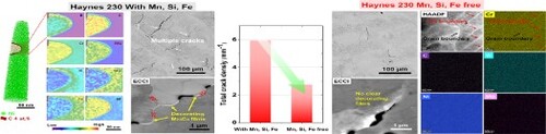
GRAPHICAL ABSTRACT
IMPACT STATEMENT
The massive cracking events in the selective-laser-melted Haynes 230 superalloy are due to the continuous decoration of an M23C6 film at grain boundaries, regardless of the detailed cracking modes.
1. Introduction
The rapid advancement of metal-based additive manufacturing (AM) technology has caused huge impacts on producing Ni-based superalloy parts in recent years [Citation1–6]. This is because the AM process features near-net & high-freedom shaping, which hits the exact demand in jet engines or gas turbines. However, the Achilles heel of the widespread equipping of AM in the superalloy field mainly lies in the easy occurrence of cracking [Citation7–13]. Two major cracking mechanisms have been proposed in the past decades referring to the case of welding. The first is hot-cracking, including solidification and liquidation cracking that originate from the reservation/formation of localized liquidation regions, e.g. low-melting-point borides or eutectic phases along grain boundaries (GBs) [Citation8,Citation14,Citation15]. The second is solid-state cracking, which occurs in pure solid-state and is driven by the accumulation of internal thermal stresses [Citation7,Citation16,Citation17].
Actually, these cracks often appear simultaneously in the AMed superalloys and are hence believed closely related to each other [Citation16,Citation18]. One proposal is that the hot cracks developed during solidification or early thermal cycles can act as nuclei for the later solid-state cracks [Citation7,Citation18]. This is probably true since stress can be concentrated easily around pre-existed crack tips. However, direct proof is lacking while a clear picture depicting different cracking paths is still missing. A scientific question then arises: can there be a single root for multiple cracks in a certain AMed superalloy?
To address the concern, in this work we built specimens of Haynes 230, a classical solid-solution-strengthened Ni-based superalloy [Citation19] via selective laser melting (SLM). Surprisingly we unravelled the continuous decoration of an M23C6 carbide film with a high-melting point at GBs that leads to most cracking events regardless of the specific cracking mode. Particular interest was paid to the segregation of impurities, i.e. Mn, Si and Fe, with the help of atom probe tomography. We believe that these findings will shed light on the future design of AM-suitable solid-solution-strengthened superalloys.
2. Materials and methods
The pre-alloyed Haynes 230 powder was produced using vacuum argon-protected gas atomization, with details described elsewhere [Citation20]. SLM processing was conducted on an SLM 125HL machine (SLM Solutions GmbH, Germany) equipped with a 400 W fibre laser (IPG) under an argon atmosphere. The processing parameters are a laser power of 160 W, a scanning speed of 1000 mm/s, a hatching space of 90 μm, a layer thickness of 30 μm, a scanning rotation angle of 67° and a baseplate temperature of 200°C. The standard composition range and also the measured chemical composition of the SLMed sample via inductively coupled plasma (ICP) are listed in Table . Overall cracking morphology was revealed by scanning electron microscopy (SEM, Helios Nanolab G3 UC) under the second electron (SE) imaging mode and the electron-channelling-contrast (ECC) imaging mode. Electron backscattered diffraction (EBSD) was also correlatively carried out on a Zeiss GeminiSEM 460 machine. Microstructure details were then probed using transmission electron microscopy (TEM, FEI Titan G2 60-300) with an objective aberration corrector operated at 300 kV. SEM/EBSD samples were prepared by minor polishing, using a 50 nm scale SiO2 suspension. TEM samples were twin-jet electro-polished in a solution of 10% HClO4 + 90% C2H6O at a direct voltage of 30 V. Atom probe tomography (APT) was carried out on a LEAP 5000XR from Cameca Instruments Inc., under a laser pulsing mode with a pulse repetition rate of 125 kHz and a pulse energy of 60 pJ. The base specimen temperature was set at 60 K, and the target detection rate was kept at 0.7%. APT needle specimens were prepared following the standard lift-out protocol in a dual-beam SEM/focused-ion-beam (FIB) instrument (Helios Nanolab 600i).
3. Results and discussion
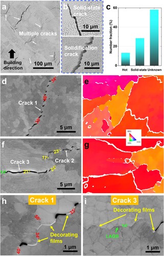
Figure a gives a cross-sectional view of the as-built microstructure. Dense distribution of cracks appears, with cracking lengths ranging from several to hundreds of microns. After carefully screening more than 200 different cracks we find that firstly, cracking occurs exclusively along normal high-angle GBs (nearly 98% in number fraction). And secondly, as shown in Figure b both hot cracks (to be more specific, solidification cracks) with an exposed dendritic arm on crack faces and solid-state cracks that are straight (many with sharp corners) exist here and there. Notice that as plotted in Figure b more than half of the checked cracks are not able to distinguish precisely under the commonly applied morphological criterion. Correlative ECCI-EBSD observations on several of those cracks are provided in Figures c–f, respectively. We number the crack in Figures c and d as crack 1, and the misorientation across the cracked GB falls in the range of 30–40° (measured from the inverse pole figure (IPF) in Figure (d)). By taking a closer view of cracks 1 and 3 in Figures h and i, respectively, we observe that both the cracks are discrete and consist of short pieces of cracks, suggesting that they are not fully opened/developed. These premature cracks allow us to collect real information about the crack-sensitive GBs right before they split into large cracks. Surprisingly, abundant linear features with the brightest contrast are found connecting those isolated short cracks. Even the uncracked low-angle GB ahead of the crack tip (the 14° one in Figure i) is continuously decorated by the brightest feature. These observations indicate that the brightest feature, probably a new phase, preliminarily covers almost all cracked GBs regardless of the misorientation value and cracking mode. This resembles the case of the so-called liquid film with low-melting-point mentioned before in the literature [Citation8,Citation16,Citation21].
Figure 1. Crack identifications in the SLMed Haynes 230 superalloy: (a) Low-magnification image showing the overall cracking status. (b) High-magnification images showing examples of a solid-state crack and a hot-crack (solidification crack). (c) Columnar charge showing the number fractions of the identified cracks and those unresolved cracks. (d, e) and (f, g) Correlated ECCI-EBSD images showing two cracked regions with three cracks numbered 1, 2 and 3; (h, i) High-magnification ECC images showing the microstructures centred on the crack 1 and 3, respectively, where film-like features are clearly observed.
The film-like phase is further characterized by TEM in Figure . We prepared a site-specific lamella sample across a cracked GB, as described in Supplementary material Figure S1. The overall TEM bright field imaging of the lamella is given in Figure a. The width of the subject crack separating the two grains (containing columnar dislocation substructures) is, to some degree, expanded during the FIB-milling process. The film-like phase, as pointed by the yellow arrow, is embedded ahead of the crack, near the sample surface. Figure b is a closer view showing the film-like phase, while Figure c gives the high-resolution TEM image centred on the phase boundary. The comparison of the fast Fourier transformation (FFT) in the insets of Figure c indicates that it is an M23C6 carbide that maintains a near-coherent {100} interface with the face-centred cubic (fcc) solid-solution matrix [Citation22]. Figure d shows the scanning transmission electron microscopy (STEM) high-angle annular dark field (HAADF) image on the M23C6 carbide and the abutted crack tip. The elemental distribution maps indicate that the carbide is enriched highly in Cr, W and Mo but slightly in Si and C. For Si/C the enrichment intensity might not be correctly reflected due to the limited EDS accuracy on light-weight elements. In addition, only Cr, W and O are found co-segregating at the crack inner face with a thickness of only 10 nm. Combining with the fact that no obvious O enrichment is detected at the crack tip carbide position (which is also in line with the APT results in Figure ), it is supposed that such oxidation occurs along the crack channel right after the crack extension during SLM, hence probably won't generate key influences on the crack onset.
Figure 2. TEM observations on the film-like phase: Bright field images showing (a) the overall view of the lift-out lamella sample and (b) the film-like phase enclosed to the crack. (c) High-resolution TEM image centred on the interface of the film-like phase and the matrix, with insets showing their FFT patterns, respectively. (d) STEM-HAADF image and the corresponding elemental maps centred on the crack tip and the carbide film.
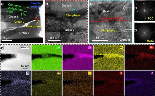
Figure 3. Atom probe tomography on the M23C6 carbide: (a) APT reconstruction with a 4.0 at.% C iso-composition surface embedded in Ni atoms showing the presence of the carbide. (b) 2D elemental distribution maps in the orange region of interest. (c, d) 1D composition profiles along the black arrow in (b).
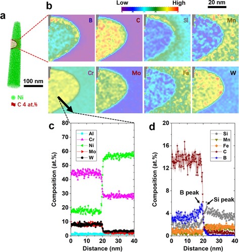
To reveal the chemistry (in particular Si, C and B) of the M23C6 carbide more precisely, we carried out APT measurements, and the results are shown in Figure . Figure a outlines the carbide-matrix interface at a 4.0 at.% C iso-composition surface. Figure b lists all two-dimensional (2D) elemental maps from the orange-coloured region of interest. The carbide enriches in C, B, Cr, Mo, W, in accordance with the TEM-EDS mapping results in Figure d except for Si. In the APT dataset Si is enriched surrounding the carbide. It is believed that the 2D overlapping of the Si-rich nano-layer with the carbide volume leads to the artifact projected by TEM. The composition of the carbide is Cr45.1-Ni17.8-C13.7-W8.3-Mo8.2-B3.0-Si1.9-other (at.%) according to the 1D composition profiles in Figures c and d, along the black arrow in Figure b. The Cr level in the carbide is detected at around 45 at.%, in line with the reported M23C6 carbide in the literature [Citation20,Citation23,Citation24]. In addition, B is probed similarly segregated towards the phase boundary in the carbide side, indicating continuous absorbance of B and repulsion of Si across the interface during the growth of the carbide.
The chemistry on low-angle GBs is also probed using APT and the results are given in Supplementary material Figure S2. The elemental segregation intensity is reasonably similar, and more likely stronger at high-angle GBs due to the higher local free energy and thus the higher segregation driving force [Citation25]. Therefore, by comparing GBs and carbide films, the apparent segregation of Cr, C and B will facilitate the formation of the M23C6 carbide by reducing the nucleation barrier, and eventually construct it as the principal element. Mo and W are also strong carbide stabilizers [Citation20,Citation23], and they indeed enrich the carbide despite no clear segregation at GBs. This is reasonable considering their 1∼2 orders of magnitude lower diffusion kinetics than the solvent Ni. However, considering the key roles played by the five elements on the temperature capability for a polycrystalline solid-solution-strengthened superalloy, it is not preferred to exclude or even reduce their amount in the alloying philosophy. Among the left, Mn, Si and Fe are found strongly repelled from the carbide, behaving just like carbide-destabilizers. This is quite interesting since that Mn and Si are often reported as crack promoters [Citation26–28]. In particular, Si is evidenced as a significant stabilizer for yet another type of carbide, M6C, and with a high tendency to enrich along multiple interfaces (as depicted in Figure d and Figure S2d) [Citation29–31]. Although Fe is seldom seen in the discussion on forming carbides in superalloys, its interaction with Cr to construct (Fe/Cr)23C6 in steels is well acknowledged [Citation32,Citation33]. To figure out whether the formation of the carbide film during SLM is related and can be enhanced by the alloying of the three elements, we carried out a combined experimental-thermo-calc investigation on an Mn, Si, Fe-free counterpart (measured composition listed in Table ), and the comparison to the current Mn, Si, Fe-containing Haynes 230 is given in Figure .
Figure 4. Combined experimental-thermo-calc investigation on the Mn, Si, Fe-free counterpart and the current Mn, Si, Fe-containing Haynes 230: (a) Columnar chart showing the measured crack density, with an inset showing the overall crack status in the Mn, Si, Fe-free counterpart; Thermo-calc simulation showing (b) the solidification path based on the Scheil-Gulliver assumption and (c) the equilibrium phase curve focusing on the M23C6, fcc and liquid phases, using the TTNI8 database.
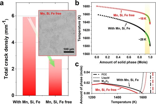
Table 1. Standard composition range and also measured composition of the SLMed Haynes 230 superalloy (the current one with, and the modified one without Si, Mn, Fe, all in wt.%).
Figure a shows the low-magnification image of the microstructure of the SLMed Mn, Si, Fe-free counterpart, where much fewer cracks appear. The measured total crack density drops substantially from 5.93 to 2.74 mm−1, indicating a lowered cracking risk by removing Mn, Si and Fe. Supplementary material Figure S3 (ECCI) and S4 (STEM) further confirm barely no similar film-like phase covering cracked GBs in this counterpart. The solutes (e.g. Cr) segregation at the dense cell boundaries, as shown in Figure S4, suggest that the reduced tendency to form M23C6 along GBs might be due to the averaged segregation intensity of certain elements towards multiple boundaries rather than GBs only, when missing Mn, Si and Fe in the system. Figure b shows the thermo-calc result on the solidification path from the Scheil-Gulliver assumption, using the TTNI8 database. We highlight the critical temperature window in the last solidification stage, , where the fraction of solid changes from 0.9 to 0.99 (a yellow coloured region in Figure b) [Citation16,Citation34]. The larger the
, the higher strain and strain rate will be generated during the very terminal stage of solidification, resulting in higher solidification cracking sensitivity. Here for the Mn, Si, Fe-free one, the
is only around half of that for the Mn, Si, Fe-containing one, also suggesting a reduced solidification cracking sensitivity, in line with Figure a. Figure c then shows the thermo-calc result on the equilibrium phase composition, including only the M23C6, fcc solid solution and liquid phases in the near-liquidation temperature range. It is shown that the upper-temperature limit of equilibrium M23C6 turns higher when including Mn, Si and Fe in Haynes 230 (black solid line vs. red solid line). This suggests that Mn, Si and Fe stabilize the M23C6 phase anyway although they do not directly construct the crystalline lattice of M23C6.
Across the observations above, we can address the same immediate structural origin for most cracks in the SLMed Haynes 230 as the formation of the M23C6 thin films along GBs. This seems in line with the reported hot-cracking mechanism being the tearing of the weak liquid film [Citation7,Citation8]. Further considering a very important fact that the carbide film itself is not of low-melting-point, as pointed out in Figure c, the hot tearing process may not follow the liquidation cracking mechanism. On the one hand, although B segregation at GBs indeed exists in our case, it remains insufficient to form those low-melting-point borides, as illustrated by Kontis et al. [Citation21] and Després et al. [Citation35]. Instead, the segregated B atoms flow into the carbide at a low concentration of ∼3 at.%. On the other hand, according to Guo et al. [Citation36] and Zhang et al. [Citation37], M23C6 can still correlate to liquidation cracking only if the carbide forms in a eutectic way, creating a low-melting-point eutectic regime along GBs. What's more, no liquidation trace is observed near or ahead of the cracked GBs. Thereby, we exclude the occurrence of liquidation cracking in the current SLMed Haynes 230.
As a new root cause for cracking in at least the current Haynes 230 superalloy, we propose the following cracking sequence associated with M23C6 films along GBs. During the terminal stage of solidification, C, B and Cr, etc. are repelled from the solidified dendrites to the surrounding liquids [Citation36]. The local enrichment of these carbide stabilizers accelerates the nucleation of M23C6 directly from the liquids, as shown in Figure c where the upper-temperature limit of the equilibrium M23C6 is nearly 20 degrees higher than the end-of-solidification temperature. Considering the extreme case where the M23C6 phase forms within the interdendritic liquids, its film-like presence will certainly block the liquid feeding hence resulting in solidification cracking nearby. Such blocking effect is reasonably stronger than that from discrete tiny spherical MC carbide or Re-enriched precipitates as claimed in the literature [Citation7,Citation14]. Nevertheless, the identification of a minor number of solidification cracks supports the conjecture above. Alternatively, in a more reasonable case where the M23C6 phase grows and coarsens continuously along the GBs during the following thermal cycles, the bonding of the carbide/fcc matrix interface is likely not strong, which could be further weakened by the Si-enriched nano-layer surrounding the carbide. The straight and large film surfaces also lower the tolerance for strain and stress partitioning and once the micro-voids initiate at the surface, they coalesce and extend fast into a long crack. This suggests that the stress-driven solid-state crack can occur much more easily along the M23C6 films, in line with the identified larger number fraction of solid-state cracks compared to hot cracks. In this context, we suppose that most of the unresolved cracks are also of solid-state type.
4. Conclusion
In this study, we reported that originating from the high-melting-point nature, the formation of the M23C6 carbide films along GBs directly leads to massive cracking events in a solid-solution-strengthened Ni-based superalloy, Haynes 230. This is seen as a general cracking origin for this specific superalloy, regardless of the GB misorientation and the specific cracking mode. By using APT, we evidenced that the segregation of Cr, C and B fundamentally triggers the nucleation of the carbide. Although the impurities, Mn, Si and Fe, are repelled from the carbide, their removal successfully suppresses cracking during SLM. This is because firstly, they enhance the solidification-cracking sensitivity by both the enlarged and the stabilized M23C6 phase over the liquidus line; and secondly, they promote the growth of the M23C6 film along GBs, which concentrates stress and causes solid-state tearing along the straight weak interfaces.
Supplemental Material
Download PDF (2.8 MB)Acknowledgement
JH thanks the technical help from Yuhao Zhou for EBSD characterization and Liuliu Han for thermo-calc simulation. JH also feels grateful for the technical support from the Institute For Advanced Study, Central South University on atom probe tomography and focus ion beam facilities.
Disclosure statement
No potential conflict of interest was reported by the author(s).
Additional information
Funding
References
- Wong KV, Hernandez A. A review of additive manufacturing. Int Sch Res Notices. 2012;2012:1–10.
- Dilberoglu UM, Gharehpapagh B, Yaman U, et al. The role of additive manufacturing in the era of industry 4.0. Proc Manuf. 2017;11:545–554.
- Attallah MM, Jennings R, Wang X, et al. Additive manufacturing of Ni-based superalloys: the outstanding issues. MRS Bull. 2016;41:758–764.
- Panwisawas C, Tang YT, Reed RC. Metal 3D printing as a disruptive technology for superalloys. Nat Commun. 2020;11:1–4.
- Cheng B, Gu J, Song M. An investigation of the microstructural evolution and tensile properties of a nickel-based GH648 superalloy manufactured through selective laser melting. Mater Sci Eng A. 2020;790:139704.
- Wang X, Carter LN, Pang B, et al. Microstructure and yield strength of SLM-fabricated CM247LC Ni-superalloy. Acta Mater. 2017;128:87–95.
- Tang YT, Panwisawas C, Ghoussoub JN, et al. Alloys-by-design: application to new superalloys for additive manufacturing. Acta Mater. 2021;202:417–436.
- Chauvet E, Kontis P, Jägle EA, et al. Hot cracking mechanism affecting a non-weldable Ni-based superalloy produced by selective electron beam melting. Acta Mater. 2018;142:82–94.
- Ramsperger M, Singer RF, Körner C. Microstructure of the nickel-base superalloy CMSX-4 fabricated by selective electron beam melting. Metall Mater Trans A. 2016;47:1469–1480.
- Lee YS, Kirka MM, Kim S, et al. Asymmetric cracking in Mar-M247 alloy builds during electron beam powder bed fusion additive manufacturing. Metall Mater Trans A. 2018;49:5065–5079.
- Carter LN, Attallah MM, Reed RC. Laser powder Bed fabrication of nickel-base superalloys: influence of parameters; characterisation, quantification and mitigation of cracking. Superalloys. 2012;2012:577–586.
- Peng H, Shi Y, Gong S, et al. Microstructure, mechanical properties and cracking behaviour in a γ′-precipitation strengthened nickel-base superalloy fabricated by electron beam melting. Mater Des. 2018;159:155–169.
- Murray SP, Pusch KM, Polonsky AT, et al. A defect-resistant Co–Ni superalloy for 3D printing. Nat Commun. 2020;11:1–11.
- Lu N, Lei Z, Hu K, et al. Hot cracking behavior and mechanism of a third-generation Ni-based single-crystal superalloy during directed energy deposition. Addit Manuf. 2020;34:101228.
- Chen Y, Lu F, Zhang K, et al. Dendritic microstructure and hot cracking of laser additive manufactured Inconel 718 under improved base cooling. J Alloys Compd. 2016;670:312–321.
- Griffiths S, Tabasi HG, Ivas T, et al. Combining alloy and process modification for micro-crack mitigation in an additively manufactured Ni-base superalloy. Addit Manuf. 2020;36:101443.
- Ramirez AJ, Lippold JC. High temperature behavior of Ni-base weld metal: part II–insight into the mechanism for ductility dip cracking. Mater Sci Eng A. 2004;380:245–258.
- Ghoussoub JN, Tang YT, Panwisawas C, et al. On the influence of alloy chemistry and processing conditions on additive manufacturability of Ni-based superalloys. Superalloys. 2020;2020:153–162.
- Yang B, Shang Z, Ding J, et al. Investigation of strengthening mechanisms in an additively manufactured Haynes 230 alloy. Acta Mater. 2022;222:117404.
- Xia T, Wang R, Bi Z, et al. Microstructure and mechanical properties of carbides reinforced nickel matrix alloy prepared by selective laser melting. Materials. 2021;14:4792.
- Kontis P, Chauvet E, Peng Z, et al. Atomic-scale grain boundary engineering to overcome hot-cracking in additively-manufactured superalloys. Acta Mater. 2019;177:209–221.
- Xiang S, Mao S, Shen Z, et al. Site preference of metallic elements in M23C6 carbide in a Ni-based single crystal superalloy. Mater Des. 2017;129:9–14.
- Bai G, Li J, Hu R, et al. Effect of thermal exposure on the stability of carbides in Ni-Cr-W based superalloy. Mater Sci Eng A. 2011;528:2339–2344.
- Wang D, Zhang J, Lou LH. Formation and stability of nano-scaled M23C6 carbide in a directionally solidified Ni-base superalloy. Mater Charact. 2009;60:1517–1521.
- Hariharan A, Lu L, Risse J, et al. Misorientation-dependent solute enrichment at interfaces and its contribution to defect formation mechanisms during laser additive manufacturing of superalloys. Phys Rev Mater. 2019;3:123602.
- Tomus D, Jarvis T, Wu X, et al. Controlling the microstructure of Hastelloy-X components manufactured by selective laser melting. Phys Procedia. 2013;41:823–827.
- Han Q, Gu Y, Soe S, et al. Effect of hot cracking on the mechanical properties of Hastelloy X superalloy fabricated by laser powder bed fusion additive manufacturing. Opt Laser Technol. 2020;124:105984.
- Tomus D, Rometsch PA, Heilmaier M, et al. Effect of minor alloying elements on crack-formation characteristics of Hastelloy-X manufactured by selective laser melting. Addit Manuf. 2017;16:65–72.
- Xu Z, Jiang L, Dong J, et al. The effect of silicon on precipitation and decomposition behaviors of M6C carbide in a Ni–Mo–Cr superalloy. J Alloys Compd. 2015;620:197–203.
- Wang YS, Guan XM, Ye HQ, et al. Effect of silicon on grain boundary carbide precipitation and properties of a cobalt-free wrought nickel-base superalloy. Superalloys. 1980;20:63–70.
- Detrois M, Pei Z, Rozman KA, et al. Partitioning of tramp elements Cu and Si in a Ni-based superalloy and their effect on creep properties. Materialia. 2020;13:100843.
- Lewis MH, Hattersley B. Precipitation of M23C6 in austenitic steels. Acta Metall. 1965;13:1159–1168.
- Oanh NTH, Viet NH. Precipitation of M23C6 secondary carbide particles in Fe-Cr-Mn-C alloy during heat treatment process. Metals. 2020;10:157.
- Zhang J, Singer RF. Hot tearing of nickel-based superalloys during directional solidification. Acta Mater. 2002;50:1869–1879.
- Després A, Antonov S, Mayer C, et al. On the role of boron, carbon and zirconium on hot cracking and creep resistance of an additively manufactured polycrystalline superalloy. Materialia. 2021;19:101193.
- Guo B, Zhang Y, Yang Z, et al. Cracking mechanism of Hastelloy X superalloy during directed energy deposition additive manufacturing. Addit Manuf. 2022;55:102792.
- Zhang W, Liu F, Liu F, et al. Microstructural evolution and cracking behavior of Hastelloy X superalloy fabricated by laser directed energy deposition. J Alloys Compd. 2022;905:164179.