
 ?Mathematical formulae have been encoded as MathML and are displayed in this HTML version using MathJax in order to improve their display. Uncheck the box to turn MathJax off. This feature requires Javascript. Click on a formula to zoom.
Abstract
By combining volume sensitive high resolution Magnetic Force Microscopy with surface sensitive X-ray Photoemission Electron Microscopy, we resolved the depth profile of a weak stripe magnetic texture and its evolution upon in-plane magnetization reversal. In contrast to previous reports, we show that the conventional weak stripe texture undergoes a well-defined undulation while the magnetic field is reversed to negative after in plane positive saturation. This transformation is strongly impacting the flux closure caps domains and a staggered Néel caps texture appears. Thanks to quantitative agreement with micro-magnetic simulations, we demonstrate that the existence of both the instability and the staggered Néel caps is intrinsic in negative applied field after positive in plane saturation. This reversal mode is characterized by a checker board pattern of alternating surface magnetic charges and by a longitudinal modulation of the in-plane component of magnetization similar to the oscillatory buckling reversal mode reported in elongated soft magnetic nanostructures.
GRAPHICAL ABSTRACT

IMPACT STATEMENT
Zigzaging magnetic weak stripes have been observed in CoFeB thin films. The characteristics of this new magnetic texture and its origins are revealed thanks to MFM and XMCD-PEEM measurements combined to micromagnetic simulations.
1. Introduction
The competition between reaction and diffusion or between different interactions leads to a variety of complex phases scaling from several millimeters down to nanometers in biology [Citation1], chemistry [Citation2] or condensed matter [Citation3,Citation4]. In the last case, the equilibrium shapes result from the competition between a short range interaction and a long range one. More specifically, in magnetic systems, the formation of a nanometric periodic modulation of the magnetization is the result of the competition between demagnetizing and domain wall energies [Citation5,Citation6]. Parallel stripes, labyrinthine maze structure or bubbles modulations have been observed in many magnetic materials with strong magnetic anisotropy perpendicular to film plane (see [Citation6–8] for example) leading to so called strong stripe structures. Studies have been devoted to highlight the mechanism of transitions between those modulated phases as shown in [Citation9,Citation10] for the stripe to bubble transformation or in [Citation11,Citation12] for the stripe to labyrinthine. Under various stimuli, applied field [Citation13], temperature [Citation14] or both [Citation15], it has been shown that this last transformation results from the progressive appearance of undulation instabilities then discontinuities (chevrons) [Citation12]. The mechanism that supports this shape modulation is the magnetic strain induced by the progressive annihilation of domains.
When the perpendicular anisotropy decreases, shape anisotropy forces the magnetization toward the film plane and only a part of it is deviating from the plane. This stabilizes a periodic texture called magnetic weak stripes in which only a small component of perpendicular magnetization develops (see inset Figure ). As for strong stripes, magnetization alternates between up and down states across the stripes to decrease the demagnetization energy. This magnetic texture was first observed in the seminal work of [Citation16] and [Citation17] using Bitter pattern technique. Its observation has been reported in many materials through the use of Lorentz Microscopy [Citation18], Magnetic Force Microscopy (MFM) [Citation7] or synchrotron techniques like X-Ray Transmission Microscopies [Citation19,Citation20]. While the numerous types and shapes of magnetization modulation domain patterns and their transformation has been widely reported in the literature for strong stripes, it appears that in the weak stripe case, only parallel stripes configurations are encountered in full films in zero applied field [Citation6]. The only report of a zigzag weak stripes texture found at remanence is due to Barturen and coworkers [Citation21]. This was explained later as being related to the cubic anisotropy of the FeGa alloy [Citation22]. During in plane magnetization reversal, the conservation of parallel stripes has been reported for FeCoAlON [Citation23], while the appearance of zigzag configurations has been reported in FeSiB by [Citation24] with no justifications provided to explain the latter. Finally, in magnetic nanostructures, as the planar component of the magnetization must follow the nanostructure edges, exotic configurations could be demonstrated [Citation25].
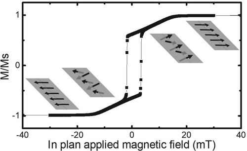
Figure 1. Hysteresis loop of a 180 nm thick CoFeB layer measured with the field applied in plane. Insets: Schematics of the magnetization profile at positive and negative saturation and in the slope of the loop.
By combining volume sensitive high resolution MFM, surface sensitive X-ray photoemission electron microscopy and micromagnetic calculations, we investigate the evolution of the depth profile of weak stripe domains during in-plane magnetization reversal. We demonstrate that the conventional weak stripe texture undergoes an intrinsic undulation instability when the magnetic field is reversed to negative values after in plane positive saturation, which transforms progressively into a zigzag pattern. The progressive evolution of the flux closure features shape at the surface vicinity—so called Néel caps—leads to the emergence of a staggered texture. The quantitative agreement with micromagnetic simulations shows that these instabilities have an intrinsic origin related to demagnetizing fields.
2. Method
An amorphous 180 nm thick CoFeB thin film was grown in an Alliance Concept UHV sputtering on a 5 nm thick Ta seed layer onto a Si(100) wafer and capped with a 5 nm thick Pt layer to prevent oxidation. The CoFeB layer was shown to be amorphous and homogeneous (see supporting material). The macroscopic hysteresis cycles were recorded using an ADE vibrating sample magnetometer with the magnetic field applied in plane. A M(H) loop is reported in Figure . It is typical of a stripe domain texture [Citation23]. Characteristic fields could be extracted: inplane saturation field, µ0HS = 16 mT and inplane coercive field, µ0HC = 2.5 mT. Magnetic imaging was performed using an Asylum MFM with in situ applied field and the X-Ray Photo-Emission Electron Microscopy (XPEEM) end station of the HERMES beamline (SOLEIL Synchrotron) [Citation26].
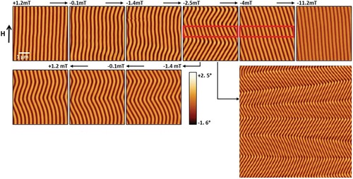
The domain pattern has been studied in situ, under inplane applied field, using MFM as reported in Figure . After saturation under a field above 20 mT, the applied field is decreased down to negative saturation. Straight weak stripes are nucleated at a field around 15mT and are straight and aligned along the applied field direction (first line, + 1.2 mT). The period increases from 320 to 360 nm when the applied field decreases from 15 mT to 0 mT (see supplementary figure). Those stripes undergo undulations when negative field is applied (Figure , first line, −0.1 mT). Increasing the negative field, the undulation amplitude increases before a transformation into the zigzag state occurs (Figure , first line, −2.5 mT). Increasing the negative field leads to straight stripes aligned with one zigzag direction (those in the red rectangle in Figure ). When the field is further decreased, from −4 mT to −11.2 mT, the stripes orient progressively towards to the field direction. If the positive to negative field sweep is stopped at −2.5 mT and progressively increased back to positive saturation, the zigzag state is preserved when the field reaches zero (Figure , second line, −0.1 mT) and it is even conserved in the positive applied field range (Figure , second line, 1.2 mT). This shows that the straight stripe to zigzag state transformation is hysteretic and the zigzag state can be observed at remanence by a proper field history (for example the one used in Figure ). A larger field of view image is given in Figure close to the coercive field (second line, right). A modulation period along the field direction between 1 and 3 µm could be measured and domain patterns close to those reported for strong stripes could be observed [Citation11–15].
Figure 2. MFM images of the weakstripes in 180 nm thick CoFeB. Top: Evolution of the weakstripe configuration under applied field from positive saturation to the negative saturation. Bottom left: Evolution of the weakstripe configuration under applied field from −2.5mT to +1.2mT after positive saturation. Bottom right: zoom out at −2.2mT (size 15µm × 15µm).
Micromagnetic calculations have been performed using MuMax3 [Citation27]. All the magnetic parameters of CoFeB have been extracted from experiments, namely a saturation magnetization MS = 1290 kA/m (measured by SQUID), an exchange stiffness constant Aex = 17 pJ/m (measured by spin-wave resonance), and an uniaxial magnetic anisotropy constant (with easy axis perpendicular to film plane) K = 36.5 kJ/m3 (measured by FMR and SQUID) [Citation28]. A discretization cell of 2.87 × 2.87 × 3nm3 has been used allowing to describe accurately the micromagnetic configuration over the range of applied field used. The micromagnetic behavior of CoFeB films with thicknesses ranging from 150 nm to 300 nm has been investigated. Obviously, the values of the critical field of stripes nucleation, stripes undulation, magnetization reversal, the stable domain sizes and the remnant magnetization are depending on the film thickness. However, all simulations show the same behavior as the one described in the following concerning the 180 nm thick film.
We used a large simulation region (Lx = 1–5 µm, Ly = 200–400 nm, where x is the direction of the in-plane field and y is the in-plane direction perpendicular to it, see Figure ). This simulation region is extended using periodic boundary conditions (PBC) in both x and y directions to emulate an extended film. These conditions are critical and we infer that previous simulation works could not address the processes described in this paper because they involved an implicit hypothesis of translation invariance along the stripe direction. Indeed, conventionally, the total volume energy density of the stripes texture is minimized by varying Ly, assuming that the stripe is straight in the longitudinal x direction (one single discretization cell is used in the x direction with a very large number of PBC repetitions to emulate an extended film). This allows to determine the stripe period by minimizing the total volume energy density with respect to Ly. Along x, i.e. along the stripes, such restricting periodic conditions are usually set to reduce the number of discretization cells and to reduce memory usage and calculation time. Indeed, at first sight, the micromagnetic problem seems to be invariant in this direction. In view of our results, this statement is obviously incorrect. In our study, Lx has been varied between 1 and 5 µm. While a single period of the undulating zigzag state could always be obtained, no clear minimum of energy with respect to the length of the simulation cell could be evidenced. In the following, Lx was fixed to 1.7 µm.
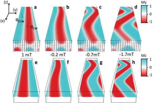
Figure 3. Micromagnetic configuration as a function of the applied field: a and e at 1mT, b and f at −0.2 mT, c and g at −0.7 mT, d and h at −1.7mT. Top line shows the micromagnetic configurations in the volume (arrows) and the My component of magnetization (color scale) for a 1mT, b −0.2mT, c −0.7mT and d −1.7 mT. This highlights the impact of the magnetization rotation on the Néel cap closure domains. Bottom line shows the Mz component of magnetization (color scale) for e 1mT, f −0.2mT, g −0.7mT and h −1.7 mT at the center of the layer. Calculations have been done for the 180 nm thick CoFeB. The size of the simulation cell along y have been adapted to find the minimum of energy whereas the size of the simulation cell along x is taken equal to Lx = 1.7 µm.
3. Results and discussion
Starting from in plane positive saturation, the applied field is progressively reduced to zero. When nucleation occurs at 14.3mT, well-defined straight stripes are obtained with a period of 270 nm as the energy minimum (see supplementary material). During the reduction of the applied field, the period of the straight stripes increases slowly to 330 nm at 0 mT. The obtained stripes texture obtained at 1 mT is shown in Figure a. From 0 mT to −0.5 mT, the decrease of the field leads to the formation of undulations. (see Figure b). This energy minimum is characterized by a period along y which increases more rapidly as compared to the corresponding unstable straight stripe case, as obtained with a single discretization cell in the x direction (not shown). A further decrease of the applied field leads to the appearance of the zigzag state (Figure , −1.7 mT). When decreasing more the applied field, the period along y increases up to 430 nm. Interestingly, the local period (measured in the direction perpendicular to the wall) is mostly constant. Those results could be obtained only when the length of the simulation cell along x is above 1 µm (only straight stripes are obtained below). This is in accordance with the undulation periodicity between 1 and 3 µm observed experimentally (Figure ).
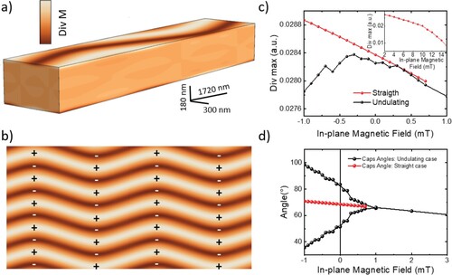
In weak stripe structures, the 3D configuration of magnetization is complex (see Figure ) but a scenario to explain the intrinsic undulation and zigzag instabilities emerges. First of all, as shown in the seminal work of Kittel [Citation5], in materials with low Q factor (), the stripe period is set by the size of the Néel caps. As a result, they play a key role in the evolution of the domain pattern. Second, a close look to the magnetization divergence (see Figure a) reveals that the volume magnetic charges are mainly stored close to the surface (dMy/dy ≈ −dMz/dz away from surface). So these charges located around the surface are responsible for demagnetization energy. The evolution of this energy under applied field can be understood through the analysis of their spatial positioning. Starting from in plane positive saturation, the decrease of the field leads to the reorientation of magnetization along the perpendicular anisotropy axis (Figure ): the perpendicular component of the magnetization increases and alternates to reduce the demagnetization field as it occurs in the strong stripe phase (Figure e). Néel caps start to appear to close the flux at the surface and surface magnetization rotates clockwise (CW) or counter clock wise (CCW) by an angle and
(Figure a) with respect to the direction of the applied field (angles always taken positive). Decreasing the field down to 0 mT reinforces this trend,
and
increases in a symmetric manner:
and the charges close to the surface increases (Figure c). At 0 mT, the magnetic texture can follow two paths: the first path is to continue this process of symmetrical rotation of the caps angles that keeps the stripes in a straight shape (red dots in Figure d). This is the process always reported in the literature which appears to be a high energy path. The second path consists in decreasing
and increasing
(black dots in Figure d). This leads to an asymmetric evolution of Néel caps closure domains and results in the formation of staggered Néel caps. In this second path, the increase of the charges is slowed down, the magnetization in the core of the layer rotates and undulation occurs (Figure g). The magnetic texture rearranges the magnetic charges from a 1D distribution towards a 2D checkerboard distribution (Figure b), leading to a further decrease of the demagnetization energy. Looking at the in-plane magnetization distribution in the center of the film (arrows in Figure g), one recognizes an oscillatory buckling process very close to the buckling reversal observed in nanostructures [Citation29] for which alternating distribution of charges occurs at the nanostructure boarders, reducing the demagnetization energy during reversal [Citation30]. Here, charges arise from the weak stripe structure. For both simulation and experiments, increasing further the field to negative values leads to the disappearance of the zigzags: the stripes finally become straight again, with their in-plane component aligned with the field direction (see Figure , −11.2 mT).
Figure 4. (a) 3D distribution of magnetization divergence. Divergence is significant at the surface; (b) Top view of the magnetization divergence at the surface with associated surface charges; (c) Maximum of surface divergence versus applied field in the case of straight (red curve) and undulating (black curve) stripes; Insert: Maximum of surface divergence versus applied field in the case of applied fields above 2mT when stripes are always straight; (d) Variation of the caps angles calculated for stripes that are forced to be straight (red dots) and for undulating stripes or zigzag domain pattern (black dots). In this last case, the angle is measured in the straight parts of the domain pattern.
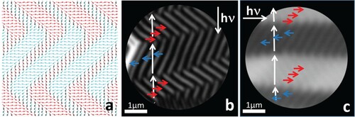
This astounding and unusual staggered flux closure domain structure has never been identified and needs the use of a surface sensitive technique to confirm its presence. Since the zigzag state has been observed at remanence by MFM, staggered Néel caps should then be observed at zero applied field. The remnant state has been observed by X-ray Magnetic Circular Dichroism Photo-Emission Electron Microscopy (XMCD-PEEM) at the HERMES beamline end station. A slight sputtering of the surface was used to remove a part of the Pt capping layer to enhance the magnetic contrast. During the acquisition, the XMCD-PEEM measurement have been performed at the Co L3 edge (777.5 eV) using left/right circularly polarized light. The X-rays are impinging the sample at grazing incidence and therefore the method is mostly in-plane surface sensitive. The sample could be rotated by 90° to get access to the two in-plane dimensional configuration. Since micromagnetism forecasts a staggered Néel caps state occurrence (Figure a) for all thicknesses between 150 and 300 nm (not shown here), the observation has been done on a 300 nm thick layer. A high resolution XPEEM image is reported in Figure b. It reveals the astounding staggered Néel caps with a transverse modulation between 1 and 3 µm. The presence of a 360° domain wall defect on the left (white contrast) asserts that surface magnetization is oriented mainly against the photon beam (black contrast) and the oblique staggered flux closure domain structure has mainly its magnetization perpendicular to the photon beam (gray contrast). Rotating the sample by 90°, highlights the magnetization orientation in the staggered caps (Figure c) with magnetization along the photon beam, either parallel or antiparallel to it, as expected from the micromagnetic simulation. This result is in perfect agreement with the magnetic simulation, and confirms the strong correlation between the stripes reversal mechanism in the volume as shown by MFM and the arrangement at the surface of the staggered Néel caps. As a result, we not only show the existence of the Néel caps that were indirectly measured by [Citation31] and that could not be observed by volume sensitive techniques [Citation18–20,Citation25] but we also show the complexity of a volume arrangement that was not reported up to now.
Figure 5. Surface magnetic configuration. (a) Surface spin texture from micromagnetic simulation showing staggered Néel caps; (b) and (c) XMCD-PEEM images measured on a 300 nm thick CoFeB in the remanent state with the beam oriented in two orthogonal directions indicated by the white arrows labeled hν. They reveal the astounding staggered Néel caps with a transverse modulation between 1 and 3 µm. (b) the surface magnetization (white arrow) is oriented mainly against the photon beam (black contrast) and the magnetization in the oblique staggered flux closure domain structure is modulated (blue and red arrow) perpendicular to the photon beam (gray contrast). (c) Rotating the sample by 90°, the magnetization in the oblique staggered flux closure domain structure (blue and red arrow) can be undoubtedly determinate.
4. Conclusion
In conclusion, during the magnetization reversal, weak stripes undergo progressive appearance of undulation and zigzag instabilities. This reversal mode has not been considered in all the proposed models of weak stripes which only consider straight stripes. As a consequence, a new phase of staggered Néel caps never predicted or observed up to now is stabilized. The origin of the progressive appearance of undulation instabilities, and then discontinuities, is new and different than the one described for strong stripes [Citation12]. For strong stripes, the mechanism that supports the shape modulation is the magnetic strain induced by the progressive annihilation of domains. The response of the magnetic texture state to this compression takes the form of a modulation of the wave vector along the stripes keeping the longitudinal component constant. In our case, the mechanism favoring this reversal mode is the gradual tightening of magnetic charges resulting from the increase of the zigzag angle.
Supplemental Material
Download MS Word (332.3 KB)Acknowledgements
The XPEEM measurements have been done on the Hermes Beamline at Synchrotron SOLEIL. The authors acknowledge the assistance from SOLEIL Hermes beamline staff. This work was partially supported by SOLEIL and the ANR SWANGATE. We would like to acknowledge the support from the French PIA project ‘Lorraine Université d’Excellence’ (ANR-15-IDEX-04-LUE) and by the Région Lorraine. Thin film growth was carried out on IJL Project TUBE-Davm equipment funded by FEDER (EU), Région Grand Est, Métropole Grand Nancy. The authors also acknowledge the High Performance Computing Center of the University of Strasbourg for supporting this work by providing access to computing resources partly funded by the Equipex Equip@Meso project (Programme Investissements d’Avenir) and the CPER Alsacalcul/Big Data. M.H. and D.L. supervised the work. D.S. performed the micromagnetic calculations. K.A.O. and D.L. performed MFM measurements. K.A.O. and R.B. performed XPEEM measurements. M.H. performed thin layer deposition. K.A.O, M.G., M.B., Y.H. and S.P. performed magnetic characterization. All the authors discussed the results and M.H., D.L. and D.S. wrote the manuscript with the help of all the authors.
Disclosure statement
No potential conflict of interest was reported by the author(s ).
Additional information
Funding
References
- Turing AM. The chemical basis of morphogenesis. Philos Trans R Soc Lond B Biol Sci. 1952;237:37–72. doi:10.1098/rstb.1952.0012
- Kapral R, Showalter K. Chemical waves and patterns. Dordrecht: Kluwer; 1995.
- Bak P. Commensurate phases, incommensurate phases and the devil's staircase. Rep Prog Phys. 1982;45:587. doi:10.1088/0034-4885/45/6/001
- Zhao G-P, Chen L, Wang J. A modified scaling law for 180° stripe domains in ferroic thin films. J Appl Phys. 2009;105:061601. doi:10.1063/1.3055355
- Kittel C. Theory of the structure of ferromagnetic domains in films and small particles. Phys Rev. 1946;70:965. doi:10.1103/PhysRev.70.965
- Hubert A, Schäfer R. Magnetic domains. New York: Springer Berlin Heidelberg; 1998; ISBN 978-3-540-64108-7.
- Hehn M, Padovani S, Ounadjela K, et al. Nanoscale magnetic domains in epitaxial cobalt films. Phys Rev B. 1996;54:3428. doi:10.1103/PhysRevB.54.3428
- Gehanno V, Marty A, Gilles B, et al. Magnetic domains in epitaxial ordered FePd(001) thin films with perpendicular magnetic anisotropy. Phys Rev B. 1997;55:12552. doi:10.1103/PhysRevB.55.12552
- Garel T, Doniach S. Phase transitions with spontaneous modulation-the dipolar ising ferromagnet. Phys Rev B. 1982;26:325. doi:10.1103/PhysRevB.26.325
- Shimada Y, Kojima H. Bubble lattice formation in a magnetic uniaxial single-crystal thin plate. J Appl Phys. 1973;44:5125. doi:10.1063/1.1662103
- Seul M, Wolfe R. Evolution of disorder in magnetic stripe domains. I. Transverse instabilities and disclination unbinding in lamellar patterns. Phys Rev A. 1992;46:7519. doi:10.1103/PhysRevA.46.7519
- Sornette D. Undulation instability in stripe domain structures of «bubble» material. J Physique. 1987;48:151. doi:10.1051/jphys:01987004801015100
- Flament C, Bacri J-C, Cebers A, et al. Parallel stripes of ferrofluid as a macroscopic bidimensional smectic. Europhys Lett. 1996;34:225. doi:10.1209/epl/i1996-00443-7
- Seul M, Wolfe R. Evolution of disorder in two-dimensional stripe patterns: “smectic” instabilities and disclination unbinding. Phys Rev Lett. 1992;68:2460. doi:10.1103/PhysRevLett.68.2460
- Molho P, Porteseil JL, Souche Y, et al. Irreversible evolution in the topology of magnetic domains. J Appl Phys. 1987;61:4188. doi:10.1063/1.338473
- Cohen MS. Anomalous magnetic films. J Appl Phys. 1962;33:2968. doi:10.1063/1.1728545
- Spain JR. Dense-banded domain structure in rotatable anisotropy permalloy films. Appl Phys Lett. 1963;3:208. doi:10.1063/1.1753851
- Ferrier RP, Puchalska IB. 360° walls and strong stripe domains in permalloy films. Phys Stat Solidi (b). 1968;28:335. doi:10.1002/pssb.19680280134
- Blanco-Roldan C, Quirós C, Sorrentino A, et al. Nanoscale imaging of buried topological defects with quantitative X-ray magnetic microscopy. Nat Com. 2015;6:8196. doi:10.1038/ncomms9196
- Ait Oukaci K, Lacour D, Stoeffler D, et al. Weakstripe angle determination by quantitative X-ray magnetic microscopy. Phys Rev Appl. 2020;14:024083. doi:10.1103/PhysRevApplied.14.024083
- Barturen M, Rache Salles B, Schio P, et al. Crossover to striped magnetic domains in Fe1− x Ga x magnetostrictive thin films. Appl Phys Lett. 2012;101:092404. doi:10.1063/1.4748122
- Billoni OV, Bustingorry S, Barturen M, et al. Anisotropy-based mechanism for zigzag striped patterns in magnetic thin films. Phys Rev B. 2014;89:184420. doi:10.1103/PhysRevB.89.184420
- Wu D, Jin T, Lou Y, et al. Understanding the dense stripe domains in soft magnetic film. Appl Surf Sci. 2015;346:567. doi:10.1016/j.apsusc.2015.04.010
- Coïsson M, Vinai F, Tiberto P, et al. Magnetic properties of FeSiB thin films displaying stripe domains. J Magn Magn Mater. 2009;321:806. doi:10.1016/j.jmmm.2008.11.072
- Hehn M, Ounadjela K, Bucher J-P, et al. Nanoscale magnetic domains in mesoscopic magnets. Science. 1996;272:1782. doi:10.1126/science.272.5269.1782
- Belkhou R, Stanescu S, Swaraj S, et al. HERMES: a soft X-ray beamline dedicated to X-ray microscopy. J Synchrotron Rad. 2015;22:968. doi:10.1107/S1600577515007778
- Vansteenkiste A, Leliaert J, Dvornik M, et al. The design and verification of MuMax3. AIP Adv. 2014;4:107133. doi:10.1063/1.4899186
- Grassi M, Geilen M, Ait Oukaci K, et al. Higgs and goldstone spin-wave modes in striped magnetic texture. Phys Rev B. 2022;105:094444. doi:10.1103/PhysRevB.105.094444
- Frei EH, Shtrikman S, Treves D. Critical size and nucleation field of ideal ferromagnetic particles. Phys Rev. 1957;106:446. doi:10.1103/PhysRev.106.446
- Steiner J. The formation of the concertina pattern: experiments, analysis, and numerical simulations [dissertation]. Mathematisch-Naturwissenschaftlichen Fakultat der Rheinischen Friedrich-Wilhelms-Universitat Bonn. http://hss.ulb.uni-bonn.de/diss.
- Dürr HA, Dudzik E, Dhesi SS, et al. Chiral magnetic domain structures in ultrathin FePd films. Science. 1999;284:2166. doi:10.1126/science.284.5423.2166