
 ?Mathematical formulae have been encoded as MathML and are displayed in this HTML version using MathJax in order to improve their display. Uncheck the box to turn MathJax off. This feature requires Javascript. Click on a formula to zoom.
Abstract
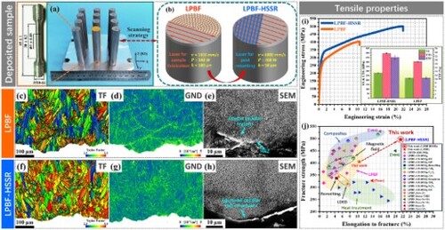
The limited mechanical properties of Al–Si alloys hinder their application in demanding and extreme conditions. The cracking tendency of high-strength aluminum alloys and high-cost of rare-earth elements pose challenges for the large-scale application of aluminum alloys in additive manufacturing. The novel and practical high-speed scanning remelting proposed in this study enables Al–Si alloys to exhibit significant proportion of fine microstructures and nano-precipitates, surpassing the mechanical properties of aluminum alloys fabricated by normal methods with exceptional strength (496.1 ± 5.8 MPa) and plasticity (21.4 ± 0.9%). This in-situ microstructure control method opens new pathways for the application in demanding engineering contexts.
GRAPHICAL ABSTRACT
1. Introduction
The development of additive manufacturing (AM) has profoundly transformed the manufacturing industry, and this technology has found applications in fields such as food [Citation1], medicine [Citation2], automotive [Citation3], and electronic components [Citation4]. In particular, in the aerospace field, which requires extremely lightweight and high-strength (∼500 MPa) components, the AM of aluminum alloys is considered a highly promising solution [Citation5]. The most serious limitation of conventional high-strength aluminum alloys (such as 2xxx, 6xxx, and 7xxx series) is the development of coarse columnar grains and cracks under AM conditions [Citation6]. Extensive efforts have been applied to computational and experimental research, including the addition of expensive rare-earth elements to aluminum alloys to promote the formation of equiaxed grains and precipitated phases [Citation7–12]. On the other hand, for cast aluminum alloys with excellent formability but low strength, such as Al–Si alloys, various additive particles have been attempted to strengthen the matrix. Unfortunately, the soft matrix of some composites is severely cut by hard particles, resulting in extremely low plasticity [Citation13–15]. Some others did not achieve the desired strengthening effect, which outweighs the high cost of additives [Citation16–18]. Only a few Al–Si-based composites have both ideal formability and mechanical properties [Citation19,Citation20]. However, to the best of our knowledge, there are still significant challenges in the process cost and stability of composite powder production.
Al–Si alloys are inexpensive and exhibit excellent formability, so researchers have attempted various auxiliary methods to improve the microstructure and mechanical performance of these alloys for AM applications. The prevalent approach involves post-heat treatments, which, while enhancing plasticity, adversely impacts tensile strength [Citation20–27]. Efforts to augment tensile strength using a static magnetic field at the substrate's base have been limited by uneven field distribution and reduced effectiveness along the build direction, making this approach unsuitable for producing large-scale samples [Citation28,Citation29]. And some others aimed to ameliorate the microstructure and mechanical properties through layer-by-layer remelting with the same process parameters (conventional remelting), but the results were minimal [Citation30]. However, the current conventional methods have not fully explored the extreme process conditions of AM. Therefore, finding an appropriate balance between process cost and mechanical performance remains a scientific and engineering challenge.
To effectively address this dilemma, we propose a feasible and economical method, in-situ high-speed scanning remelting (HSSR), to simultaneously enhance the strength and plasticity of the AlSi10Mg alloy produced by laser powder bed fusion (LPBF). This approach utilized thermal accumulation from the initial melting stage to mitigate temperature gradients in the molten pool and enhanced the solidification rate during the high-speed remelting stage, promoting the grains/cellular sub-structures refinement, columnar-to-equiaxed transition (CET), and precipitation of nano-particles. The resulting material demonstrates superior strength-plasticity synergy compared to the aluminum alloys/composites processed by standard LPBF and other methods to date.
2. Materials and methods
This study used gas-atomized AlSi10Mg alloy powder with a size of 15–53 μm. Addressing the challenges of direct high-speed melting, the powder layer was first melted under the optimal parameters based on our prior study [Citation31]. While the HSSR process increased both the scanning speed and laser power to obtain refined microstructure. It has been reported that the scanning direction has an impact on the tensile crack propagation behavior [Citation32], so an interlayer rotation of 67° was uniformly adopted in these experiments. The key process parameters are listed in Table . All specimens were cylindrical with a diameter of 12 mm and a height of 70 mm.
Table 1. Deposition and HSSR process parameters.
The microstructures were examined using a field-emission scanning electron microscopy (FE-SEM, Carl Zeiss-Gemini SEM 500), equipped with an electron backscatter diffraction (EBSD) detector. Kikuchi patterns were collected at a 0.5 μm step size and analyzed using AZtecCrystal software. A double Cs-corrected transmission electron microscope (TEM, FEI-Themis Z) was used for the dislocation observation. The foils for TEM observation were thinned by electropolishing. At least ten images were used for the measurements and statistical analyses of the microstructure using the Image-Pro Plus 6.0 software.
The specimens used for tensile testing had parallel lengths of 30 mm, diameters of 5 mm, and an extensometer gauge length of 25 mm was used following the ASTM E8/E8 M-08 standard [Citation33]. The uniaxial and loading-unloading-reloading (LUR) tensile tests were conducted under a universal testing machine (Instron 3382) at a strain rate of 6.7 × 10⁻⁴ s−1 at room temperature. Three tensile tests were repeated for each group of samples. Additionally, a finite element method (FEM) model, based on heat transfer and implemented in Abaqus software, was developed to study the solidification behavior.
3. Results and discussion
Figure (a) illustrates the typical molten pool morphology of the LPBF-processed AlSi10Mg alloy. Within the molten pool, coarse columnar grains predominantly grow along the BD, with a thin layer of equiaxed grains observable at the molten pool boundaries (MPBs) (Figure (a1)). The distribution of geometrically necessary dislocations (GNDs) is mostly concentrated inside the molten pool (Figure (a2)). Pole figure (PF) in Figure (b) reveals a strong <100 > texture in the sample. The molten pool interior is mainly composed of elongated cellular sub-structures (Figure (e)), and there are slight of precipitated nano-particles inside the α-Al matrix. (Figure (g)).
Figure 1. Microstructure of the LPBF and LPBF-HSSR samples. (a–a2) (i–i2) Band contrast (BC), inverse pole figure (IPF), and GND distribution maps of the samples. (b) (j) PF images of (a1) (i1), respectively. (c–d) (k–l) Grain equivalent diameters and aspect ratios, respectively. (e–f) (m–n) SEM images and aspect ratios of the cellular sub-structures. (g–h) (o–p) SEM images and size distributions of the precipitated nano-particles.
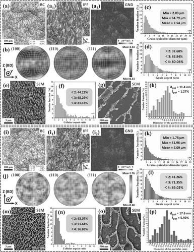
By contrast, the contour of the molten pool presented by periodic changes in the solidified grain structure is not apparent (Figure (i)), which is due to the great increase in the volume fraction of fine equiaxed grains cause by HSSR strategy (Figure (i1)). There are more GNDs in the interior of the molten pool (Figure (i2)). PF in Figure (j) further demonstrates that the crystal texture is considerably diminished through HSSR process. In addition, the interior of the molten pool is mainly occupied by nearly equiaxed cellular sub-structures (Figure (m)), which is different from the LPBF sample. But it is obvious that there are a large number of nano-particles precipitated from the α-Al matrix. (Figure (o)). The quantitative data in the bar charts shows that after remelting, the equivalent diameters of the grains were smaller (Figure (c,k)), while the equiaxed nature of the grains and cellular sub-structures was enhanced (Figure (d, f, l, n)). The size of precipitated nano-particles slightly increased, while the proportion significantly increased from ∼1.27% to ∼5.92% (Figure (h, p)).
The solidification conditions inside the molten pool in LPBF (Figure (a)) and LPBF-HSSR samples (Figure (b)) were compared through FEM. After the normal powder melting track, high-speed and high-power laser remelting was implemented. The HSSR technique results in an extended trailing longitudinal section of the molten pool. However, the impact of thermal accumulation from the initial laser melting is significant in shaping the temperature field and morphology of the HSSR molten pool.
Figure 2. Molten pool temperature field and solidification conditions. (a–b) Longitudinal cross-sections of the temperature field in the molten pool for LPBF and LPBF-HSSR specimens, respectively. (c–d) Comparative analysis of temperature gradient , growth rate
, and cooling rate
at the isothermal melting interface for LPBF and LPBF-HSSR specimens. (e) Solidification maps illustrating
and
values under LPBF and HSSR conditions.
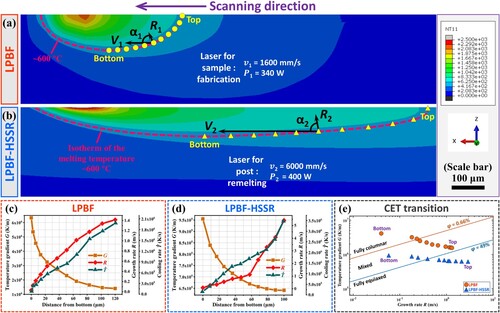
During HSSR, both scanning speed and laser power were increased, leading to significant alterations in the morphology of the isothermal melting surface that influence the solidification conditions. Given that solidification direction is perpendicular to the liquid–solid interface, the growth rate is influenced by the laser scanning speed
and the angle
between them (
) [Citation34]. Although the increase in
at equivalent pool depths during HSSR, coupled with the nearly four-fold increase in scanning speed, results in higher
values at the solidification front compared to standard LPBF. Additionally, due to the thermal accumulation from the preceding normal melting, the temperature gradients
within the molten pool during HSSR were approximately an order of magnitude lower than in the LPBF sample (Figure (c, d)).
Significant changes in solidification conditions led to a distinct solidified microstructure in the LPBF-HSSR sample. Primarily, the HSSR method promotes the refinement of grains and cellular sub-structures. The product of the temperature gradient and the growth rate
determines the cooling rate
at the solid–liquid interface front [Citation35]. It is evident that the cooling rate in the LPBF-HSSR sample surpasses that of the LPBF sample (Figure (c, d)). A higher cooling rate diminishes grain size by increasing nucleation sites and constitutional undercooling ahead of the solid–liquid interface [Citation36]. Furthermore, the changes of
and
caused by HSSR strategy can effectively minimize the size of cellular sub-structures according to the non-equilibrium KGT model [Citation37].
Regarding the morphology, it is challenging to achieve fine equiaxed grains under the normal LPBF solidification conditions. While a few equiaxed grains may form at the molten pool’s top, they tend to disappear due to remelting in subsequent adjacent layer depositions [Citation38]. In the LPBF sample, a thin layer of equiaxed grains formed near the MPBs due to the presence of broken Si particles in the HAZ, but their volume fraction is minimal (<10%) [Citation39]. Conversely, the HSSR process mostly falls within the mixed and even equiaxed zones of solidification parameters. This shift causes grains to grow with an equiaxed tendency following the CET model [Citation40] (Figure (e)). Consequently, the LPBF-HSSR sample exhibits a substantial increase in the volume fraction of equiaxed grains and cellular sub-structures (Figure (i–l)).
As for the nano-particles in the α-Al matrix, it is necessary to consider the two continuous stages: rapid solidification and in-situ solid-state phase transformation [Citation41]. The high-speed moving heat source causes solute segregation at the liquid–solid front, then a formation of the supersaturated solid solution in the matrix. As the solidification rate increases, the degree of supersaturated solid solution becomes more significant [Citation35], providing sufficient kinetics for the precipitation of nano-particles [Citation42]. Additionally, the thermal cycling numbers have been increased by remelting, and the hatch spacing in the HSSR process is half of that in the LPBF process, which makes the thermal cycling effect more significant. The supersaturated Si element undergoes a cyclic precipitation-dissolution process under the strong thermal cycling effect of the HSSR strategy, ultimately leading to an increase in both the size and quantity of nano-particles [Citation43].
Figure (a) shows representative engineering stress–strain () curves, and the characteristic values of axial tensile performance are listed in Table . Compared to the LPBF samples, the yield strength (YS), fracture strength (FS), elongation to fracture (ETF), and elastic modulus (E) of the LPBF-HSSR samples increased by 27.3%, 22.5%, 103.8%, and 7.1%, respectively. Moreover, from the comparison chart of tensile strength-plasticity in Figure (b), it can be seen that the tensile properties obtained by the LPBF-HSSR method herein is superior to that of aluminum alloys/composites fabricated by other processes to date [Citation7–30, Citation43–54].
Figure 3. Uniaxial tensile properties. (a) Representative engineering stress–strain () curves. (b) Comparison of mechanical properties of the current LPBF-HSSR sample with those reported for LPBF [Citation44–53], heat treatment (HT) [Citation21–27], laser-directed energy deposition (LDED) [Citation43,Citation54], magnetic field (MF) application [Citation28,Citation29], remelting [Citation30], composite materials [Citation13–20], and high-strength aluminum alloy [Citation7–12]. (c) True stress (
) and work-hardening rate (
) plotted against true strain (
) with an inset showing a detailed view. (d) Work-hardening exponent (
) values across different strain stages.
![Figure 3. Uniaxial tensile properties. (a) Representative engineering stress–strain (σ−ϵ) curves. (b) Comparison of mechanical properties of the current LPBF-HSSR sample with those reported for LPBF [Citation44–53], heat treatment (HT) [Citation21–27], laser-directed energy deposition (LDED) [Citation43,Citation54], magnetic field (MF) application [Citation28,Citation29], remelting [Citation30], composite materials [Citation13–20], and high-strength aluminum alloy [Citation7–12]. (c) True stress (σt) and work-hardening rate (Θ) plotted against true strain (ϵt) with an inset showing a detailed view. (d) Work-hardening exponent (n) values across different strain stages.](/cms/asset/33104f9f-d5ec-4e13-b5bb-cf8de238ee32/tmrl_a_2370853_f0003_oc.jpg)
Table 2. Uniaxial tensile properties.
The work-hardening rate (, defined as
) is plotted against true strain (
) (Figure (c)). As strain increases, the
initially decreases sharply before settling into a plateau with a gradual decline post the elastic-plastic deformation transition. The inset shows that while the
of the LPBF sample is higher in Stage I, the LPBF-HSSR sample surpasses it in Stage II. The work-hardening exponent (n) based on Hollomon’s equation (
, where
is the strength coefficient) was calculated under various tensile strain stages. Initially, the LPBF sample demonstrates superior work-hardening ability, but in later stages, the LPBF-HSSR sample exhibits a higher exponent, indicating that the enhanced work-hardening capacity contributes to the improvement of tensile strength (Figure (d)).
The HSSR method significantly alters the microstructure in the material, as previously discussed. To elucidate the deformation mechanism in samples processed by different melting strategies, LUR tensile testing and fracture analysis were conducted on both sample groups [Citation55]. It can be seen from the true LUR stress–strain curves (Figure (a)) and evolution of stress components (Figure (b)) that the LPBF-HSSR sample exhibited higher back-stress () during the entire tensile process. And the proportion of effective stress (
) in the flow stress (
) continues to raise as the strain increases in the LPBF-HSSR sample (Figure (c)).
Figure 4. LUR tensile testing and fracture analysis. (a) LUR tensile testing results for both samples. (b) Evolution of the ,
, and
during tensile testing. (c) Proportion of the
in total
(
) at varying strain levels. (d–d’) (g–g’) IPF and TF images near the tensile fracture, respectively. (e–e’) (h–h’) GNDs and BC images of the blue box regions in (d) and (g), respectively. (f) (i) SEM images of the blue box regions in (e) and (h), respectively. (j–l) Dislocation evolution near the fracture under different strains.
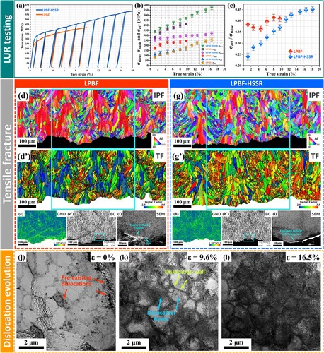
Furthermore, there are great differences in the tensile fracture characteristics between the two contrasts. It is generally believed that the MPBs are the weak regions that control the mechanical behavior of LPBF sample [Citation39,Citation48]. Firstly, the presence of a thin layer of equiaxed grains at the MPBs, these areas served as transition zones with large and fine grains. This configuration led to poor coordinated deformation ability in these zones, resulting in stress concentration and an elevated GNDs (Figure (e)) [Citation56,Citation57]. Secondly, the heterogenous cellular sub-structures of the MPBs (fine cells, course cells, and broken Si particles in the HAZ region) promote MPB decohesion [Citation39,Citation58]. When the MPBs can no longer sustain the increased stress at a certain strain level, cracks form and propagate rapidly along these boundaries (Figure (e’, f)). Therefore, the microstructure characteristics and mechanical properties limitations of AlSi10Mg alloy under normal LPBF process have been prominent, and innovative methods are urgently needed to break these constraints.
Through HSSR, the tensile properties of AlSi10Mg alloy have been greatly improved, attributed to the contributions of microstructure adjustment:
Grains refinement and texture weakening. After HSSR, the decrease in grain size is accompanied by an increase in the proportion of equiaxed grains. During the tensile process, the regions with clusters of fine equiaxed grains contribute to harder areas (with high Taylor factors), and regions with clusters of columnar grains lead to softer areas (with low Taylor factors) (Figure (g’)) [Citation59]. Compared to the LPBF sample (Figure (d’)), the microstructure of LPBF-HSSR greatly enhances the coordinated deformation ability between grains to further weaken the stress concentration in the MPBs (Figure (h)), thereby preventing preferential crack propagation along the MPBs (Figure (h’, i)), and improving tensile plasticity [Citation60].
Refined cellular sub-structure. The unique intragranular cellular sub-structure of LPBF-processed AlSi10Mg alloy plays a crucial role in the mechanical performance. On the one hand, there is a circle of eutectic Si phase around the cellular α-Al matrix to hinder the dislocations movement. The smaller the cellular size, the more pronounced of the Hall-Petch effect and the higher of the yield strength [Citation61]. On the other hand, it has been confirmed that the cellular sub-structure is the origin of the work-hardening ability of LPBF-processed AlSi10Mg alloy. The Orowan looping formed by the interaction between the eutectic Si phase and dislocations is identified as the dominant strengthening mechanism [Citation62]. The finer the cellular boundary, the higher of the
, and the more prominent of the work-hardening ability, which has been evidenced by the high
Increased grain/cellular boundary density and precipitated nano-particles. The refinement of grains and cellular sub-structures inevitably introduced a higher density of grain/cellular boundary interfaces in LPBF-HSSR sample, leading to more dislocation accumulation at these interfaces. Besides, the HSSR strategy leads to the production of a large number of precipitated nano-particles in the matrix (Figure (o)), which can effectively generate dislocation forests (Figure (j–l)). This accumulation not only contributes to back-stress hardening but also enhances dislocation hardening to improve the mechanical properties of the alloy [Citation63], which is consistent with the continuously increasing
4. Conclusion
The HSSR technique is considered a groundbreaking and practical method for the in-situ modification of the microstructures and mechanical properties of alloys formed using LPBF, offering significant potential for future applications. Improving the proportion of refined equiaxed grains can significantly release strain localization at the MPBs, thereby delaying decohesion and improving the ductility of the specimen. Refining the cell structure and increasing the boundary density and precipitated nano-particles can effectively elevate the work-hardening capacity, ultimately increasing the tensile strength. The impact of HSSR-processed Al–Si alloys on anisotropy, fracture toughness, and fatigue performance, which are of great concern in the aerospace field, will be explored in our future work.
Supplemental Material
Download MS Word (14.4 MB)Disclosure statement
No potential conflict of interest was reported by the author(s).
Data availability statement
All relevant data are within the manuscript and its Additional files.
Additional information
Funding
References
- McCaw JCS, Fleck TJ, Tejada-Ortigoza V, et al. Vibration-assisted printing of highly viscous food. Addit Manuf. 2022;56:102851.
- Kuang X, Rong Q, Belal S, et al. Self-enhancing sono-inks enable deep-penetration acoustic volumetric printing. Science. 2023;382:1148–1151. doi:10.1126/science.adi1563
- Wiese M, Thiede S, Herrmann C. Rapid manufacturing of automotive polymer series parts: a systematic review of processes, materials and challenges. Addit Manuf. 2020;36:101582.
- Gerges T, Semet V, Lombard P, et al. Rapid 3D-plastronics prototyping by selective metallization of 3D printed parts. Addit Manuf. 2023;73:103673.
- Gradl P, Mireles OR, Katsarelis C, et al. Advancement of extreme environment additively manufactured alloys for next generation space propulsion applications. Acta Astronaut. 2023;211:483–497. doi:10.1016/j.actaastro.2023.06.035
- Dixit S, Liu S. Laser additive manufacturing of high-strength aluminum alloys: challenges and strategies. J Manuf Mater Process. 2022;6:156.
- Zhang H, Zhu H, Nie X, et al. Effect of zirconium addition on crack, microstructure and mechanical behavior of selective laser melted Al-Cu-Mg alloy. Scr Mater. 2017;134:6–10. doi:10.1016/j.scriptamat.2017.02.036
- Ma S, Shang Z, Shang A, et al. Additive manufacturing enabled synergetic strengthening of bimodal reinforcing particles for aluminum matrix composites. Addit Manuf. 2023;70:103543.
- Bayoumy D, Schliephake D, Dietrich S, et al. Intensive processing optimization for achieving strong and ductile Al-Mn-Mg-Sc-Zr alloy produced by selective laser melting. Mater Des. 2021;198:109317. doi:10.1016/j.matdes.2020.109317
- Wang Z, Lin X, Kang N, et al. Making selective-laser-melted high-strength Al–Mg–Sc–Zr alloy tough via ultrafine and heterogeneous microstructure. Scr Mater. 2021;203:114052. doi:10.1016/j.scriptamat.2021.114052
- Mehta A, Zhou L, Huynh T, et al. Additive manufacturing and mechanical properties of the dense and crack free Zr-modified aluminum alloy 6061 fabricated by the laser-powder bed fusion. Addit Manuf. 2021;41:101966.
- Martin JH, Yahata BD, Hundley JM, et al. 3D printing of high-strength aluminium alloys. Nature. 2017;549:365–369. doi:10.1038/nature23894
- Chen Y, Ren Y, Li K, et al. Laser powder bed fusion of oxidized microscale SiC-particle-reinforced AlSi10Mg matrix composites: microstructure, porosity, and mechanical properties. Mater Sci Eng A. 2023;870:144860. doi:10.1016/j.msea.2023.144860
- Gao C, Liu Z, Xiao Z, et al. Effect of heat treatment on SLM-fabricated TiN/AlSi10Mg composites: microstructural evolution and mechanical properties. J Alloys Compd. 2021;853:156722. doi:10.1016/j.jallcom.2020.156722
- Zhao Z, Bai P, Misra RDK, et al. Alsi10mg alloy nanocomposites reinforced with aluminum-coated graphene: selective laser melting, interfacial microstructure and property analysis. J Alloys Compd. 2019;792:203–214. doi:10.1016/j.jallcom.2019.04.007
- Zang C, Liu W, Zeng M, et al. The influence of NH3 plasma treatment on microstructure and mechanical property of AlSi10Mg alloy fabricated by selective laser melting. Mater Today Commun. 2023;34:105274. doi:10.1016/j.mtcomm.2022.105274
- Lu Z, Han Y, Gao Y, et al. Effect of nano-Si3N4 reinforcement on the microstructure and mechanical properties of laser-powder-bed-fusioned AlSi10Mg composites. Crystals. 2022;12:366. doi:10.3390/cryst12030366
- Zhang F, Zhang Z, Gu Q, et al. Microstructure and mechanical properties of nanoparticulate Y2O3 modified AlSi10Mg alloys manufactured by selective laser melting. Materials. 2023;16:1222. doi:10.3390/ma16031222
- Feng Z, Wang G, Hao Z, et al. Influence of scale effect on surface morphology in laser powder bed fusion technology. Virtual Phys Prototy. 2024;19:e2336157.
- Tan Q, Zhang J, Mo N, et al. A novel method to 3D-print fine-grained AlSi10Mg alloy with isotropic properties via inoculation with LaB6 nanoparticles. Addit Manuf. 2020;32:101034.
- Takata N, Kodaira H, Sekizawa K, et al. Change in microstructure of selectively laser melted AlSi10Mg alloy with heat treatments. Mater Sci Eng A. 2017;704:218–228. doi:10.1016/j.msea.2017.08.029
- Girelli L, Tocci M, Gelfi M, et al. Study of heat treatment parameters for additively manufactured AlSi10Mg in comparison with corresponding cast alloy. Mater Sci Eng, A. 2019;739:317–328. doi:10.1016/j.msea.2018.10.026
- Wang CG, Zhu JX, Wang GW, et al. Effect of building orientation and heat treatment on the anisotropic tensile properties of AlSi10Mg fabricated by selective laser melting. J Alloys Compd. 2022;895:162665. doi:10.1016/j.jallcom.2021.162665
- Wang LF, Sun J, Yu XL, et al. Enhancement in mechanical properties of selectively laser-melted AlSi10Mg aluminum alloys by T6-like heat treatment. Mater Sci Eng A. 2018;734:299–310. doi:10.1016/j.msea.2018.07.103
- Padovano E, Badini C, Pantarelli A, et al. A comparative study of the effects of thermal treatments on AlSi10Mg produced by laser powder bed fusion. J Alloys Compd. 2020;831:154822. doi:10.1016/j.jallcom.2020.154822
- Pramod S, Naveen KM, Kesavan D. Effect of part orientation and low-temperature annealing on impact toughness of laser powder bed fusion-processed AlSi10Mg. J Mater Eng Perform. 2023;32:393–405. doi:10.1007/s11665-022-07083-x
- Zyguła K, Nosek B, Pasiowiec H, et al. Mechanical properties and microstructure of AlSi10Mg alloy obtained by casting and SLM technique. World Sci News. 2018;104:456–466.
- Zhou H, Song C, Yang Y, et al. Effect of axial static magnetic field on microstructure evolution, performance, and melt pool signals of AlSi10Mg fabricated by laser powder bed fusion. Opt Laser Technol. 2023;163:109316. doi:10.1016/j.optlastec.2023.109316
- Du D, Haley JC, Dong A, et al. Influence of static magnetic field on microstructure and mechanical behavior of selective laser melted AlSi10Mg alloy. Mater Des. 2019;181:107923. doi:10.1016/j.matdes.2019.107923
- Zhou J, Han X, Li H, et al. Investigation of layer-by-layer laser remelting to improve surface quality, microstructure, and mechanical properties of laser powder bed fused AlSi10Mg alloy. Mater Des. 2021;210:110092. doi:10.1016/j.matdes.2021.110092
- Cao Y, Lin X, Wang QZ, et al. Microstructure evolution and mechanical properties at high temperature of selective laser melted AlSi10Mg. J Mater Sci Technol. 2021;62:162–172. doi:10.1016/j.jmst.2020.04.066
- Khosravani MR, Frohn-Sörensen P, Engel B, et al. Fracture behavior of double edge notch AlSi10Mg alloy fabricated by laser powder bed fusion. Theor Appl Fract Mech. 2024;130:104349. doi:10.1016/j.tafmec.2024.104349
- ASTM E8/E8M-08. Standard test methods for tension testing of metallic materials. West Conshohocken (PA): ASTM International; 2013.
- Azizi H, Ebrahimi A, Ofori-Opoku N, et al. Characterizing the microstructural effect of build direction during solidification of laser-powder bed fusion of Al-Si alloys in the dilute limit: a phase-field study. Acta Mater. 2021;214:116983. doi:10.1016/j.actamat.2021.116983
- Kurz W, Fisher DJ. Fundamentals of solidification. Durnten-Zurich, Switzerland: Trans Tech Publications; 1992.
- Easton MA, StJohn DH. Improved prediction of the grain size of aluminum alloys that includes the effect of cooling rate. Mater Sci Eng A. 2008;486:8–13. doi:10.1016/j.msea.2007.11.009
- Kurz W, Giovanola B, Trivedi R. Theory of microstructural development during rapid solidification. Acta Metall. 1986;34:823–830. doi:10.1016/0001-6160(86)90056-8
- Thijs L, Kempen K, Kruth JP, et al. Fine-structured aluminium products with controllable texture by selective laser melting of pre-alloyed AlSi10Mg powder. Acta Mater. 2013;61:1809–1819. doi:10.1016/j.actamat.2012.11.052
- Delahaye J, Tchuindjang JT, Lecomte-Beckers J, et al. Influence of Si precipitates on fracture mechanisms of AlSi10Mg parts processed by selective laser melting. Acta Mater. 2019;175:160–170.
- Gäumann M, Bezençon C, Canalis P, et al. Single-crystal laser deposition of superalloys: processing–microstructure maps. Acta Mater. 2001;49:1051–1062. doi:10.1016/S1359-6454(00)00367-0
- Kirka MM, Nandwana P, Lee Y, et al. Solidification and solid-state transformation sciences in metals additive manufacturing. Scr Mater. 2017;135:130–134. doi:10.1016/j.scriptamat.2017.01.005
- Liu M, Fu H, Xu C, et al. Precipitation kinetics and hardening mechanism in Al-Si solid solutions processed by high pressure solution treatment. Mater Sci Eng A. 2018;712:757–764.
- Shi S, Lin X, Wang L, et al. Investigations of the processing–structure–performance relationships of an additively manufactured AlSi10Mg alloy via directed energy deposition. J Alloys Compd. 2023;944:169050. doi:10.1016/j.jallcom.2023.169050
- Li X, Yi D, Wu X, et al. Effect of construction angles on microstructure and mechanical properties of AlSi10Mg alloy fabricated by selective laser melting. J Alloys Compd. 2021;881:160459. doi:10.1016/j.jallcom.2021.160459
- Maconachie T, Leary M, Zhang J, et al. Effect of build orientation on the quasi-static and dynamic response of SLM AlSi10Mg. Mater Sci Eng A. 2020;788:139445. doi:10.1016/j.msea.2020.139445
- Ch SR, Raja A, Nadig P, et al. Influence of working environment and built orientation on the tensile properties of selective laser melted AlSi10Mg alloy. Mater Sci Eng A. 2019;750:141–151.
- Hitzler L, Janousch C, Schanz J, et al. Direction and location dependency of selective laser melted AlSi10Mg specimens. J Mater Process Technol. 2017;243:48–61. doi:10.1016/j.jmatprotec.2016.11.029
- Paul MJ, Liu Q, Best JP, et al. Fracture resistance of AlSi10Mg fabricated by laser powder bed fusion. Acta Mater. 2021;211:116869. doi:10.1016/j.actamat.2021.116869
- Zhao L, Macías JGS, Douillard T, et al. Unveiling damage sites and fracture path in laser powder bed fusion AlSi10Mg: comparison between horizontal and vertical loading directions. Mater Sci Eng A. 2021;807:140845. doi:10.1016/j.msea.2021.140845
- Read N, Wang W, Essa K, et al. Selective laser melting of AlSi10Mg alloy: process optimisation and mechanical properties development. Mater Des. 2015;65:417–424. doi:10.1016/j.matdes.2014.09.044
- Larrosa NO, Wang W, Read N, et al. Linking microstructure and processing defects to mechanical properties of selectively laser melted AlSi10Mg alloy. Theor Appl Fract Mech. 2018;98:123–133.
- Patakham U, Palasay A, Wila P, et al. MPB characteristics and Si morphologies on mechanical properties and fracture behavior of SLM AlSi10Mg. Mater Sci Eng A. 2021;821:141602. doi:10.1016/j.msea.2021.141602
- Uzan NE, Shneck R, Yeheskel O, et al. High-temperature mechanical properties of AlSi10Mg specimens fabricated by additive manufacturing using selective laser melting technologies (AM-SLM). Addit Manuf. 2018;24:257–263.
- Kiani P, Dupuy AD, Ma K, et al. Directed energy deposition of AlSi10Mg: single track nonscalability and bulk properties. Mater Des. 2020;194:108847. doi:10.1016/j.matdes.2020.108847
- Yang M, Pan Y, Yuan F, et al. Back stress strengthening and strain hardening in gradient structure. Mater Res Lett. 2016;4:145–151.
- Otani Y, Takata N, Suzuki A, et al. Microstructural origin of anisotropic tensile ductility of Al-Si alloy manufactured by laser powder bed fusion. Scr Mater. 2023;226:115259. doi:10.1016/j.scriptamat.2022.115259
- Liu Q, Wu H, Paul MJ, et al. Machine-learning assisted laser powder bed fusion process optimization for AlSi10Mg: new microstructure description indices and fracture mechanisms. Acta Mater. 2020;201:316–328. doi:10.1016/j.actamat.2020.10.010
- Eom YS, Park JM, Choi JW, et al. Fine-tuning of mechanical properties of additively manufactured AlSi10Mg alloys by controlling the microstructural heterogeneity. J Alloys Compd. 2023;956:170348. doi:10.1016/j.jallcom.2023.170348
- Park JM, Choe J, Park HK, et al. Synergetic strengthening of additively manufactured (CoCrFeMnNi)99C1 high-entropy alloy by heterogeneous anisotropic microstructure. Addit Manuf. 2020;35:101333.
- Chen H, Patel S, Vlasea M, et al. Enhanced tensile plasticity of an additively manufactured AlSi10Mg alloy by reducing the density of melt pool boundaries. Scr Mater. 2022;221:114954. doi:10.1016/j.scriptamat.2022.114954
- Li Z, Li Z, Tan Z, et al. Stress relaxation and the cellular structure-dependence of plastic deformation in additively manufactured AlSi10Mg alloys. Int J Plast. 2020;127:102640. doi:10.1016/j.ijplas.2019.12.003
- Chen B, Moon SK, Yao X, et al. Strength and strain hardening of a selective laser melted AlSi10Mg alloy. Scr Mater. 2017;141:45–49. doi:10.1016/j.scriptamat.2017.07.025
- Jiang Y, Xu R, Tan Z, et al. Interface-induced strain hardening of graphene nanosheet/aluminum composites. Carbon. 2019;146:17–27. doi:10.1016/j.carbon.2019.01.094