Abstract
In recent years, there has been an increased demand in the use of multiple unmanned aerial vehicles (UAVs) in indoor environments such as material handling task in a manufacturing environment and plant/environment monitoring task in a greenhouse. However, there is a lack of work reported on this topic. This paper presents a detailed study on several UAV systems and UAV scheduling systems. It is followed by a proposed system of UAV application in indoor environment, which comprises components of UAV system addressed in detail; focused on scheduler as the heart of operations. Consequently, system architecture of UAV scheduling system is presented and the framework of scheduler component is included. Scheduler component works in a phased manner to provide a systematic abstraction and achieve an efficient computation time. This study serves as a reference guide for UAV application in indoor environment.
1. Introduction
In manufacturing and production companies, various operations/tasks are gradually being automated – to be performed by robots instead of human labors. These automation robots include Unmanned Ground Vehicle (UGV) and Unmanned Aerial Vehicle (UAV). UGV, whose nature is operating on the ground, has been widely used for manufacturing tasks like part-feeding and material handling (Dang, Nielsen, Steger-Jensen, & Madsen, Citation2014; Vivaldini, Rocha, Becker, & Moreira, Citation2015). UAV, which is operating in the air, is emerging in various application domains such as surveillance, logistics, and search–rescue missions. Recent applications of UAVs in outdoor environments have been addressed in (Bareth, Aasen, & Bendig, Citation2015; von Bueren et al., Citation2015; Pérez-Ortiz et al., Citation2015). But, UAV applicability is not only limited to those outdoor applications, UAVs can also be useful in indoor environments for manufacturing/service (e.g. hospitals, greenhouses, production companies, and nuclear power plant). Equipped with an imaging device and sensor, UAV can be used for performing inspection tasks in harsh environment, both visual and sensorial inspection. Equipped with a gripper, UAV can also be used for performing material handling task in a manufacturing environment to feed materials to the production line. Together with this applicability, the employment of UAVs in indoor environment is also supported by various advantages such as 360° inspection angle of an object in a three-dimensional space and operability in an empty upper-air space (which has been an idle area in the era of UGV). As a result, in a greenhouse for instance, UAV can be very flexible to perform visual inspection on tall or short plants and sense the chemical level of the environment without any distance limitation toward the wall – like the conventional stationary sensor has. On the other side, some difficulties are involved due to narrow spaces and obstacles, as well as the denial of global positioning system (Bejuri, Wan, Mohamad, & Sapri, Citation2011) in indoor environment. With recent technological advancements, UAVs can be equipped with video camera, laser range finder, motion capture system, and wireless communication technologies (Bareth et al., Citation2015; He, Prentice, & Roy, Citation2008; Kwon & Hailes, Citation2014; Mellinger, Michael, & Kumar, Citation2012) which enable UAV employment for indoor operations.
Research on UAV applications in indoor environments (He et al., Citation2008; Macallister, Butzke, Kushleyev, Pandey, & Likhachev, Citation2013; Mellinger et al., Citation2012; Nigam, Bieniawski, Kroo, & Vian, Citation2012) is emerging in the latest decade, and focus on UAV scheduling in such environment (Kim & Morrison, Citation2014) is at an early stage. Research on surveillance missions in indoor environments has been conducted on UAVs which utilizes schedule and image recognition of the specified target (Kim & Morrison, Citation2014; Song et al., Citation2014). Specifically, the studied UAVs focus on the scheduling of split jobs of long surveillance missions; to maintain a persistent UAV operation. UAVs with special equipment can also facilitate material handling systems by moving materials between different locations in an indoor establishment.
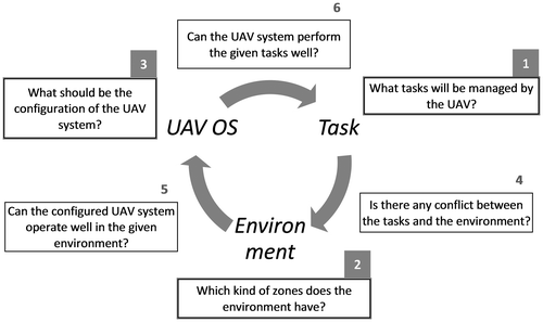
There are three elements to be considered in employing UAVs for a certain application domain: task, environment, and UAV operation system (UAV OS). Task is an activity which will be performed by UAVs. Different types of task include material handling, quality inspection, and area surveillance mission. Environment is the surroundings and infrastructure where the UAV system will be employed. UAV operation system contains different types of UAVs (equipped with gripper, imaging device, and sensor), recharge centers and other resources which support UAV operation. These elements affect each other in a chain reaction and form six groups of requirement as shown in Figure . To analyze this chain reaction, one has to check the following requirements: (1) The nature of the task shall be defined. Types of tasks to perform and the respective attributes, forbidden actions (e.g. landing at random positions on the flying path), and planning requirements such as objectives and constraints are formulated. (2) Based on the characteristics of each area (e.g. area with undetermined-state doors, area with constant/periodical air turbulence), the whole environment is classified into several zones (e.g. no restriction zone, UAV-free zone, and conditional UAV-free zone). Accordingly, the methods to handle each zone are determined. (3) Detailed configuration of the UAV OS such as type and specification of the UAVs, number of UAVs, and position and capacity of recharge centers are then decided. Afterwards, requirements (4)–(6) are defined based on the interactions among these elements. When there is a change of design, the respective requirements have to be redefined and the affected elements should be checked in sequential and iterative manner.
For instance, (1) UAVs are employed to perform inspection tasks on wind turbines (on predetermined points of interest) (2) in an indoor wind turbine production facility, where UAV is allowed to fly through. (3) UAV(s) equipped with a camera shall fly through a predefined path plan (according to the defined points of interest) supported by the indoor positioning system, and scheduler shall assign which UAV to inspect which point of interest on which wind turbine in what order. From this point, let’s assume that (4) there are inaccessible points of interest on the rear part of the wind turbine, which is outside the confined space of indoor positioning system due to its lengthy shape. As a solution, (5) some additional satellites are installed to extend the confined space to cover the rear part of the wind turbine. (6) Finally, it is confirmed that the inspection tasks can be performed without any trouble.
Due to the more cramped area in indoor environment compared to outdoor, there is less flexibility in dodging when a potential collision is met. Hence, flight during tasks execution must be scheduled in non-colliding paths. In other words, risks of damage on both UAVs and resources (e.g. human worker, machine on shop floor) are exposed. Therefore, indoor UAV application has more constraints and precise controls to be taken into account.
UAV schedule mainly presents the activity execution plan of each UAV, with details of task assignment and their execution timestamp. An efficient UAV schedule is vital to minimize UAV operation cost (Kim, Gu, & Postlethwaite, Citation2007; Kim, Song, & Morrison, Citation2013; Semiz, Citation2015; Shima & Schumacher, Citation2005; Weinstein & Schumacher, Citation2007), which can be achieved by minimizing the makespan or battery consumption of the UAVs. In addition, when UAVs are operated in indoor environment with other capital intensive resources, UAV schedule needs to fit well in the resource schedule to maintain resource utilization as high as possible. Hence, developing an efficient scheduler is needed in the UAV system.
The contribution of this paper is in defining a UAV system with detailed configurations and constraints, which are required for a UAV application in indoor environment, accompanied by studies of related works. In the UAV system, a time-efficient scheduler works as an engine to utilize the resources. A proposed framework of scheduler and system architecture of UAV scheduling system, together with the presented UAV system (scheduler and other components – as a whole), constitute the main contribution of this work.
The remainder of the paper is organized as follows. In section 2, existing UAV systems (of indoor and outdoor applications) and UAV scheduling systems are compared and examined. Section 3 describes the environment of indoor UAV operations. Section 4 presents the details of the developed system architecture of UAV system and UAV scheduling system. Section 5 presents the proposed framework of the scheduler component and the involved phases. Section 6 addresses a discussion about the conditions and limitations of the study. Section 7 concludes the work in this paper.
2. Literature review
In the last decades, UAV applications for various purposes and environments are designed in diversified UAV systems. In this paper, a UAV system for scheduling executions of multiple tasks by multiple UAVs in indoor environment is addressed. To illustratively distinguish the requirement of the comprised components, several UAV systems are compared and shown in Table .
Table 1. Various UAV systems comparison.
From Table , it is seen that for outdoor environment (studies of Pérez-Ortiz et al., Citation2015; Tso, Tharp, Zhang, & Tai, Citation1999), it is perfectly feasible to use the conventional Global Positioning System (GPS) for localization/positioning system. However, for indoor environment, He et al. (Citation2008), Mellinger et al. (Citation2012), Nigam et al. (Citation2012), and Macallister et al. (Citation2013) had to use alternatives such as laser rangefinder and motion capture system. With laser range finder, at least one reference point which is known by the positioning system needs to be defined and the latter location of the UAVs in the confined space is approximated through the sensed movement, which may contain a margin of error. On top of that, in an environment cluttered with huge machines (like in manufacturing environment), the sensed perimeter will be biased. On the other side, motion capture system is more reliable but it comes with a high cost of the high-resolution cameras which are needed to capture the marker (attached on the UAV) throughout the confined three-dimensional space. Furthermore, mapping in indoor environment also needs to be exclusively performed and could not rely on the satellite (geographical) map data. Besides objects in the three-dimensional indoor environment, information about feasible paths in the respective free aerial space needs to be included in the map as well. It is to ensure the reasonability of schedule optimization upon the given tasks later. If the path alternatives from one position to another are unknown in the beginning, optimization cannot be done since the execution time of each task cannot be assessed. In addition, a narrower space (compared to outdoor) and uncertain events on-the-fly (e.g. falling wire from the ceiling) require a precise control and responsive alteration of the planned task execution schedule. Thus, a novel UAV system which accommodates a precise mapping, localization, UAV control, together with a fast good-quality schedule with uncertain-event awareness is needed for robust three-dimensional indoor UAV operations.
Table shows that the reported work on task-based UAV scheduling in three-dimensional indoor environment is missing. Tso et al. (Citation1999) addressed a task planning using a real-time simple dispatching rule when a primitive task is encountered. In that era, UAV is still not highly exposed to various application domains. In the latest decade, several works begin to arise in regard to UAV scheduling. Ahner et al., Weinstein et al., Kim J. et al., Kim Y. et al., Zeng et al. addressed UAV scheduling in outdoor environment. Due to the key differences (which is elaborated in Section 5) of UAV scheduling for indoor operations from outdoor, a study on indoor UAV scheduling is demanded.
Table 2. Various UAV scheduling systems comparison.
In Song et al. (Citation2014) (a further work of Kim et al., Citation2013), Song et al. presented a brief test of UAV handoff operation schedule in indoor environment, where the UAV follows a moving surveillance target, and considered it to be more disturbance-free than outdoor environment. However, various other indoor environments are relatively narrow (compared to outdoor; hence a precise flight management is required) and more constrained (e.g. flight altitude – distance toward ceiling and possibly other UAVs, restricted zones in a manufacturing environment). Not to mention, disturbance in indoor environment varies, for example, in industrial environment, compressed air pipe leak might cause air turbulence around the flight path. Hence, a UAV system which employs multiple UAVs for performing multiple tasks across such environment within a minimized makespan is highly challenging.
Pérez-Ortiz et al. (Citation2015) addressed a flight planning of an observation task on a sunflower field. This operation only plans a single flight upon the field to conduct a visual inspection of the crops. The nature of the task here does not require an extensive schedule search like the multiple task-based operations do. Semiz presented a task assignment and scheduling work in (Semiz, Citation2015), but the problem differs quite dramatically since the environment is assumed to be constraint free and 2D (two dimensional). As a result, a study of multiple tasks based 3D indoor UAV scheduling in this paper comes in to fill the gap. In the next section, descriptions about the comprised components in indoor UAV scheduling system are presented in detail.
3. Environment in indoor UAV operations
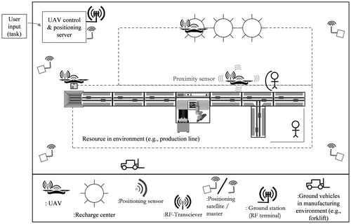
This section describes the environment variables which should be taken into account when UAVs are employed for indoor UAV operations, with a manufacturing environment as an instance. An instance of manufacturing environment is formulated in Figure . It depicts UAVs operating in a dedicated flying space (no other element’s presence shall pass/collide with this space) to establish a robust safe operation. UAVs may land only on a recharge station to avoid any casualty toward both UAVs and environment. Despite this confinement, the UAV is also equipped with a proximity sensor to face unexpected encounter with other object on-the-fly. Areas of production line are remain untouched, and positioning satellites (which send signals to the receivers attached on the UAVs) are installed surrounding the confined space. At last, the positioning sensor sends measurement data to the server, while Radio Frequency (RF) transceivers attached on the UAVs can communicate directly with the server for command and control purpose. In such environment, there are at least three factors to consider: UAV flying space boundary, uncertain event and topology of the environment itself. On top of that, a UAV system which comprises map (trajectory) system, UAV control system, indoor positioning system and scheduler is addressed in Section 4.
3.1. UAV flying space boundary
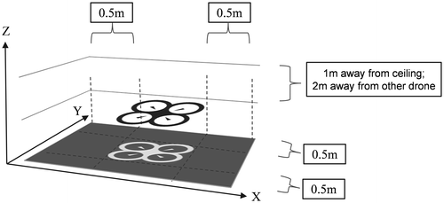
When a UAV flies, it creates air turbulence above and below the propellers of the UAV. This has to be taken into account when layers of path are considered in the environment map. Figure depicts an example of flying space boundary of a UAV built by Sky-Watch A/S (Citation2016) tested in the laboratory. The testing site resembles a small or medium manufacturing environment which is occupied with workstations, stationary and mobile ground robots, conveyer belts, workbenches, ventilation pipes, forklifts, cables, and other manufacturing equipment. This measurement may vary, to correspond with the UAV design and environment condition. From the Z-axis perspective, a UAV requires a significant distance from another to avoid flight disturbance.
3.2. Uncertain event
In indoor UAV operations, there exist various potential uncertain events. In a manufacturing environment, for instance, there might be machine breakdown, dropping wire, UAV engine failure and even an unexpected closed door which yields an infeasible path. Furthermore, to overcome any unexpected reason which causes the UAV trajectory collides with a human labor or ground vehicle, a fail-safe equipment such as proximity sensor shall be integrated with the UAV. These uncertain events, from both UAV and environment, contribute to the occurrences of tardy jobs which eventually create schedule nervousness – requiring the schedule to be modified or regenerated.
3.3. Topology
In manufacturing environment, there are multiple machines with various sizes, in regard to the three-dimensional size, especially the height (dimension along Z-axis). When UAVs are employed in indoor environment, the upper space in the corridor is used as its primary transportation media. Yet the UAV might expose two potential risks to the objects in the environment. First, an object which spans and reaches the height of the flying layer might alternate the path in the map in a non-intersecting manner; so that no UAV crash into it. The second potential risk is a damage to the object when the UAV experiences a failure and hence falls on top of it. With the propeller still probably running, the fallen UAV may give a notable physical damage to the object.
4. System architecture for indoor UAV application
This section presents the proposed system architecture when UAV is implemented in indoor environment. Indoor UAV system includes four major components: map and path planning system, scheduler, indoor positioning system, and UAV control system. Details of components and data communication are presented, as well as a lab-stage demonstration of the UAV system is presented in this section. The detailed system architecture of UAV scheduling system and its interactions with other components are also explained.
4.1. Architecture of UAV system
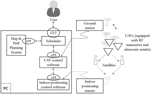
UAV system in indoor environment mainly comprises map and path planning system, indoor positioning system, UAV control system, and scheduler. Physical architecture of the UAV system implementation is depicted in Figure as a physical architecture.
Map system provides the information of possible trajectory in the environment where the UAV may pass through and perform tasks. Possible trajectories of a particular task is one of the inputs for the scheduler to determine the order of execution for the tasks at hand. It is passed through an Application Programming Interface (API) which is implemented as a static library in this study. Another input to the scheduler is three-dimensional coordinate of the UAV from the indoor positioning control software. It is obtained by the scheduler through the API of UAV control software, where originally it is fed by indoor positioning control software through its API. In this manner, scheduler will have a one-stop access in getting the UAV status and its position over time from UAV control software. The location of the UAV is used for monitoring the task executions by the UAVs and displayed to the user via a Graphical User Interface (GUI). Apart from the monitoring purpose of the user, scheduler uses this information for indicating the need of schedule modification or rescheduling process (e.g. due to job tardiness) to anticipate potential collision in the original schedule, which has become infeasible (refer Section 5.2 for further details on framework of scheduler). A more detailed system architecture which focuses on UAV scheduling system is explained in the following section.
4.2. Architecture of UAV scheduling system
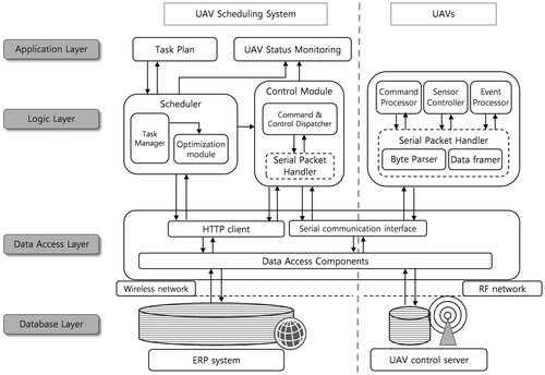
UAV scheduling system (USS) contains scheduler component and databases. The architecture of USS is shown in Figure . The role of this system is to schedule execution of tasks on demand and monitor the UAV operations according to the given schedule. According to multi-layer architecture paradigm (Fowler, Citation2002), the proposed system is depicted in four layers, which are described as follows:
| • | The application layer describes the interaction between user and USS. It is a user interface layer where user can input and update task information (e.g. new task entry, modify task execution position, modify task name), as well as monitor UAVs operations. | ||||
| • | The logic layer describes methods which are used to process task plan and generate a schedule. It includes optimization module and control module. The optimization module is responsible for generating optimal task execution, whereas control module is responsible for packaging and sending instruction to the UAV control server. The UAV control server will manage the final low level commands to the UAVs in the representation of sequence of bytes. The details of these two modules are described in the following workflow. When there is a change in the task data-set, it may change the time efficiency of current task execution schedule on a particular planning horizon. In other words, a new schedule is required. New schedule is generated by the optimization module in regard to the predefined objectives (e.g. makespan minimization, energy minimization, and resource utilization maximization). A new schedule cannot be directly transferred to the UAVs. It is necessary to build a control module to transform the task execution schedule into a set of instructions which complies with the UAV execution command protocol. Control module also acts as an instruction buffer, which will broadcast commands through Radio Frequency (RF) network to the UAVs which are listening on the designated frequency. UAV receives the incoming command, sends a feedback that the command is received, executes it accordingly, and sends another feedback when the task is completed. Then, the feedback is relayed to control module by the UAV control server, and consequently sends the instruction for the next available task to the respective UAV. Actions which are done by control module and feedbacks from the UAVs will be shown later through the UAV status monitoring module. | ||||
| • | The data access layer at both USS and UAVs connects them with database in the database layer. Basically, data access layer provides interfaces for fetching and storing data from and to databases. To access task information, USS communicates with the Enterprise Resource Planning (ERP) system through wireless network via a predefined database port. On the UAV control server side, a simplified database exists to record activity log. In this manner, a seamless data retrieval can be established from the logic layer regardless of changes occurred in the database layer. | ||||
| • | Database layer is the lowest level abstraction in the system architecture where the data is stored. There are two types of database involved: integrated database at the ERP system and log database at UAV control server. The integrated database represents data which is used throughout the company or enterprise, while the log database is limited to activity log recording for troubleshooting purpose when un-expected event occurs. Main data which is retrieved from ERP system is task data which needs to be scheduled and executed. Activity log data related to UAV operations is only stored locally to avoid unnecessary data in the ERP database. | ||||
4.3. Components
In indoor UAV scheduling system, various components are comprised which include map and path planning system, indoor positioning system, UAV control system, and scheduler.
4.3.1. Map and path planning system
Indoor environment mapping in the addressed UAV system includes available positions and possible paths between each pair of positions. On top of that, possible path plans from an origin position toward a destination position are calculated dynamically. This means, given a set of paths which is blocked at a particular time, an alternative path plan, whose paths exclude the blocked set, is computed. In this manner, a preventive method of anti-collision flight is performed.
4.3.2. Indoor positioning system
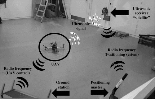
As aforementioned in Table , indoor positioning system might employ laser rangefinder or motion capture system. In this proposed UAV system, a radio-based positioning system is used. A positioning master, satellites (receiver), and senders (ultrasonic transmitter) from GamesOnTrack A/S (Citation2016) are used. Satellites are put around the area that needs to be covered, where each satellite might reach up to 7–8-m radius. These satellites will receive ultrasonic signal from the senders when they are moving inside the coverage area. The set up of positioning system provides the location of UAV with 10 mm precision. Figure depicts the communication links among sender, satellite, and master of indoor positioning system via ultrasonic and radio frequency signal.
| • | Interface with UAV control system | ||||
Position of the UAVs is provided to UAV control software which enables the UAV to navigate within an indoor environment. Through this interface, a near real-time feed of coordinates of the UAV in the confined space at a particular time can be obtained. When the coordinate readings are not as the UAV control software expected, a corresponding follow-up action, such as a straightforward outlier filtration, may be performed. In addition, this coordinate data is also accessible by scheduler, allowing a potential schedule adjustment (e.g. delay insertion or rescheduling) to be done accordingly in a near real-time manner.
4.3.3. UAV control system
During the operations, UAVs receive commands and send status updates from and to a ground station. This ground station communicates with a control software on a computer which do more complex & required computation/processes. The two elements constitute a UAV control system which holds the bridge between scheduler and UAVs. Commands (translated from schedule) from scheduler are sent to control software and forwarded to the respective UAVs to be executed. When the task is started, completed, or interrupted, an acknowledgment is sent to the ground station. UAV position and status (e.g. battery level) are also sent periodically at a predefined rate to the ground station. These data are relayed back to the scheduler via control software to decide the possibly required alteration or simply for monitoring purpose (displayed to user). In this study, UAV ground station and control software from Sky-Watch A/S (Citation2016) are used. Figure depicts the communication link between transceiver and ground station which works based on radio frequency signal.
4.3.4. Scheduler
The scheduler receives inputs from map and path planning system, UAV control system, and task database (refer Figures and ). Trajectory database contain information regarding the physical features of the indoor environment (e.g. maps and flight path). The scheduler provides instructions to UAVs and gets the status update of UAVs through the UAV control server. The information of the tasks to be executed is stored at a task database.
| • | Interface with map and path planning system | ||||
This interface is responsible for providing a seamless interaction between scheduler and trajectory system which gives path planning data as input for the scheduling process. Through this interface, scheduler can retrieve waypoints (in the path plan) between positions in the environment which the UAVs need to fly through. In addition, scheduler can send updates from UAVs regarding environment disturbance to trajectory system so that other UAVs won’t take routes which are potentially unsafe nearby the disturbed zones.
| • | Interface with UAV control system | ||||
This interface is responsible for providing a seamless interaction between scheduler and UAV control system. Through this interface, scheduler can send instruction based on the schedule to the respective UAVs and receive feedbacks. These feedbacks include instruction-retrieval acknowledgment, UAV status during task execution, and task completion acknowledgment for monitoring and rescheduling consideration purpose.
5. Framework of scheduler
As depicted in Figure and explained in Section 4.3, scheduler is the heart of UAV system in the addressed system architecture which administers the executions of the given tasks by the available UAVs.
5.1. Hierarchy of schedule and map
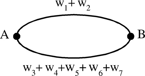
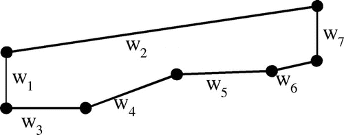
The scheduler develops a flight schedule and distributes the tasks to UAVs. There are two levels of flight schedule and map: high and low. A high level schedule contains tasks and execution timestamps for each UAV. A more detailed low level schedule specifies execution timestamps and physical routes of each subtask (action). A high level map is depicted in Figure . This high level map leaves out the details of physical components so that the number of steps in the scheduling model is admissible for computation. However, low level map consists of paths (edges) and turns (positions) represented as parameterized layers in a 3D trajectory layout (Khosiawan, Nielsen, Do, & Yahya, Citation2016), depicting all waypoints of a path from one position to another, as shown in Figure . Each low level position (turn) is defined as a three-dimensional point. In the proposed UAV system, a path is defined to accommodate one UAV at a time. To avoid inefficient path blocking, segmentation is done according to the operational flying speed of the UAV in indoor environment, so that there is no path which is too long (which causes lengthy waiting time) nor too short (which causes a high risk of collisions).
The proposed scheduler works in phases, produces a high level schedule, and derives a low level schedule based on it. High level abstractions of map and schedule decrease the domain size; hence, computation size and time are minimized. Figure shows the example of high level flight schedule. Each UAV has a high level schedule which is translated afterward into low level schedule. This low level schedule is referred to generate exact commands to UAV to fly from one waypoint to another. High level schedule includes task, flight between tasks, and hover, wait-on-ground, and recharge. Low level schedule includes flight plan via multiple waypoints (which is encapsulated as toω in high level schedule) as well as actions of a respective task; e.g. pickup & release of payload, take photo.
Figure illustrates UAV operations from time 0 till 1000 which corresponds with the schedule depicted in Figure . Task 5 is executed immediately after task 2 is completed by UAV1 because at timestamp 305, it is already at the execution position of task 5 – no flight required (like flight towards position D ‘toD’ is required to execute task 6 after task 5).
Apart from the obvious additional time, an inefficient task execution order may sensitively affect the battery consumption. UAV has a limited battery capacity; its consumption rate is quite high (which is a perfect call for a giant battery with more capacity) but its physical weight shall not be too heavy in order to avoid too much payload during the flight. If it has too lengthy unnecessary flight operations, it will hit a frequent number of recharge, which eventually explodes the total makespan. This condition signifies the essential role of a schedule in managing the task executions with capacitated resources to achieve a minimized makespan.
5.2. Framework of the scheduler component
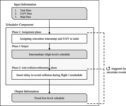
Due to the complexity of the problem, the objective is to find a feasible schedule. In this manner, the computation time is shortened. Timeliness is necessary because the scheduler needs to respond to uncertain events in an online mode (during the schedule execution). Furthermore, necessary recharges, which depend on the task execution timestamp and UAV assignment, add complexity to the scheduling process. Consequently, a scheduler is designed in a framework of phases, which gives a clear chronology for solving such a complex problem.
The scheduler framework consists of two phases: assignment (with recharge insertion), and anti-collision refinement. This phase partition is necessary because the problem becomes too complex when the task assignment and a low level routing problem are considered simultaneously. In addition, recharging time tends to be longer than the flight time. Consequently, to establish the phase-based scheduling framework, each round of flight can be modeled independently without considering recharges between flights. In Figure , the scheduler framework is presented. The system receives inputs which include map (path planning) data, UAV status data (e.g. UAV operating state, current position, destination position, and battery level), and task data.
The scheduler starts with phase 1 to assign UAV and execution time for each given task. This assignment process follows predefined constraints modeled in the UAV system, which can be formulated as a heuristic. Heuristic approaches toward a scheduling problem are assessed in (Song et al., Citation2014), which addresses their superiority in terms of computation time over (MILP model solved by) CPLEX. Scheduling constraints in a UAV platform for task executions in indoor environment are included as follows.
| • | A successor task can be executed if and only if its predecessor(s) are completed. | ||||
| • | Path planning involved in the schedule generation considers the blocked paths at a particular time (preventive anti-collision method). | ||||
| • | A position shall not be over occupied by a number of UAVs which eventually expose collision threat among them. | ||||
| • | A battery recharge is performed when a UAV doesn’t have enough battery to go to at least a nearest UAV after a task completion. When such condition occurs, a recharge is performed before the task is executed. | ||||
| • | Task is not subdivided into subtasks. When a task includes a flight (e.g. in material handling task), then the flight time is taken into account as part of execution time of the respective task. It is for preserving high level abstraction of the entity in the scheduling process to minimize computation time. | ||||
| • | Execution time of a task (i.e. flight time toward execution position, task execution time, combined with flight time toward a nearest recharge station/home base) must not exceed maximum battery capacity. In correspondence with the indivisible task characteristic, a material handling task execution time includes time for material pickup, flight toward release position, and material release itself. | ||||
The aforementioned constraints may differ to some extend according to the specific application domain characteristics and policies.
After phase 1, an intermediate (high level) schedule is obtained, which consider anti-collision path planning for every task. It means that scheduler is keeping track of the occupied path during some respective periods of time, according to the produced schedule so far. Hence, during the schedule generation, scheduler will assign a UAV to fly through a path at a certain period of time in a collision-free manner. In relation to this preventive anti-collision path method in the aforementioned map system (Section 4.3.1), phase 2 comes in to satisfy the anti-collision criteria by adding a delay to the respective UAV schedule where the intersecting path due to uncertain events occurred later on-the-fly. Depending on the type of uncertain event, which the occurrence time is unpredicted, the treatment may be different. For instance, machine breakdown is best treated with a reschedule to eliminate obsolete tasks. These treatments will be investigated properly in the future to provide a prompt response toward the schedule nervousness on-the-fly. The exact length of the delay time can be pre-formulated to correspond to the number of intersecting UAVs through simulations/experiments.
Furthermore, from the scheduling perspective, UAV scheduling in three-dimensional indoor environment comprises key differences (from outdoor) as follows.
| (1) | Precise flight management It is supported by an accurate map data and actual available path data. A path is segmented in a predefined length where it is blocked when a UAV is passing through it. The predefined length of the blocked path is supposed to cover as long as safety can be guaranteed, but also efficient to not block a lengthy path, which may cause a traffic congestion. In addition, multiple layers in a corridor might be preferred to minimize detour, due to the occupied shortest path, when possible. Scheduler takes an active part in keeping track of paths which are blocked at some periods of time. This information will be an input for the path plan query during the schedule generation process. | ||||
| (2) | Supplementary actions In between the tasks, several supplementary actions are potentially required to make a feasible schedule for UAV operations. These actions include hover, wait-on-ground, and recharge. Several conditions which require additional action insertion are depicted in Figure and described as follows. | ||||
| • | UAV reaches a required position while the position is still occupied. UAV shall hover around the position, since it is not safe to just land anywhere on the field; only landing at recharge station is allowed. Figure (a) depicts a sequence of actions where a UAV most recently flies toward an occupied position, hovers for a while, and finally perform a task at the freed (available) position. | ||||
| • | UAV is at a recharge station, and the next target position of the UAV is not available. When this condition occurs, it is better for the UAV to wait-on-ground instead of start to fly right away and hover around afterward because the position is still occupied. Figure (b) depicts a sequence of actions where a UAV is at a recharge station (performing recharge or simply being idle in the beginning of planning horizon), wait-on-ground for a while because its destination (position) is occupied, and finally fly toward the start position of the task to be performed next. | ||||
| • | Recharge is to be performed at a recharge station and all slots are still occupied. When this condition occurs, UAV shall wait-on-ground till one of them is free. Figure (c) depicts a sequence of actions where a UAV is going to perform a recharge while all slots in the designated recharge stations are occupied. When it arrives at the recharge station, it performs wait-on-ground until one of the slots is free, and recharge eventually. | ||||
| (3) | Fast schedule generation In an indoor environment, obstacles are more concentrated in a narrow space, which more likely interfere with the UAV flight path. This means, apart from a sense-and-report capability of the UAV (e.g. proximity sensor), the UAV system must possess a robust scheduler which can react in a real-time manner. In some cases, a local obstacle avoidance (on the UAV) might be done (resulting in delay-insertion in the schedule), but for some others, a new schedule generation might be required. For instance, a machine which is used for executing a task is broken, then the respective tasks become obsolete, including their successors. With the original schedule, the objective might be poorly satisfied (e.g. a lengthy makespan due to unnecessary recharge). In this case, a new schedule which excludes those tasks is best suited to solve the problem. As depicted in Figure , apart from delay-insertion, uncertain event may also trigger reassignment of the tasks, which is needed for the aforementioned latter case. In the end, with the fast-computation nature of heuristic-based approach, a feasible solution (schedule) with a good objective value (total makespan) can be obtained to satisfy the need of a fast schedule generation. | ||||
6. Discussions
To execute tasks in an indoor environment with capacitated UAVs, which are operating under a UAV operation system (involving indoor positioning system and UAV control system), a detailed specification of nature of those three elements is essential. Furthermore, to have a smooth (anti-collision) and time-optimized operation, a scheduler is required. Scheduler builds an order of task executions in a time-efficient manner. A selected chain of tasks is preferred to have less (unnecessary) waiting (hover or wait-on-ground) and travel between positions. On top of that, scheduler keeps track of the occupied paths when a schedule is built; generating an anti-collision offline schedule (referred as phase 1). When it is online, uncertain events might occur and cause nervousness to the established schedule. This is where the delay insertion or rescheduling (referred as phase 2) is performed, which will be properly investigated in a later study.
In this study, the proposed UAV platform is partly implemented and case specifically described as follows.
| • | A task abstraction is indivisible. For instance, there are two types of task: inspection and material handling, which are considered. Inspection task comprises an action of taking photo at a position, while material handling task comprises a pickup at origin position, a flight towards destination position, and a release (of the picked-up material/payload) action at the destination position. | ||||
| • | Positions of interest in a manufacturing environment are provided in the map data. | ||||
| • | Objects (non-free-space area) in the environment are mapped as cuboids to provide a robust (static-obstacle-free) mapping of positions and paths. | ||||
| • | For indoor positioning system, an ultrasonic-based sensor is used. A device called ‘sender’ can be easily attached and removed to support a tractable UAV deployment. The sender attached on the UAV transmits ultrasonic signal to the receiving satellite attached on the wall (of indoor environment). Then, the satellite relays the readings through radio frequency current to a device called ‘master,’ which forwards the data to a computer to be processed by a software application. | ||||
| • | Regarding the UAV control system, a control software and ground station is involved. The UAV performs an action upon the received command from ground station. These commands are translated from schedule and buffered at the control software. In return, UAV also provides status update (e.g. acknowledgment message) to the ground station (which is relayed to the control software and accessible by scheduler). | ||||
Not to mention, coherent interfaces (which can be implementation-wise flexible) among the components (i.e. map and path planning system, indoor positioning system, UAV control system, and scheduler) as mentioned in section 4.3 also contribute to the constitution of UAV system.
The idea of the proposed system can be applicable for various indoor environments (such as manufacturing environment, greenhouse, and nuclear power plant) as long as the elements and components are properly conformed. When a particular UAV application in indoor environment is being established, an iterative check is performed toward the three elements: task, environment, or UAV operations system. And for every distinguished characteristic from either of the elements, a constraint can be defined to adjust the affected components: map & path planning system, indoor positioning system, UAV control system, or scheduler, respectively. Specifically, from the scheduler perspective, it can be formulated into an adjustment toward the heuristic approach of the schedule generation and search process.
7. Conclusion
There is an increased demand in the use of UAVs in indoor environment, and the development of technologies allows such novel UAVs application. From the literature, it is found that research in the area of UAV in indoor environment is in the early stage. Yet it is emerging and promising to be investigated further for various application domains. In manufacturing environment, for instance, UAV application offers the off-shop-floor operations, allowing the idle upper-air space to be utilized instead of the crowded ground. To achieve a smooth and efficient UAV operations in indoor environment, a robust UAV system is needed (as a whole entity of the associating components), especially a scheduler (as a component to schedule the execution of tasks on demand and monitor the UAV operations according to the given schedule) as the heart of UAV system. This paper presents a detailed study of existing UAV systems and (more focused) UAV scheduling systems, followed by a proposal of both (UAV system and UAV scheduling system) for indoor environment, presented in a detailed architecture and descriptions. This study focuses on scheduling system as an essential component for operating multiple UAVs in indoor environment. Detailed architecture of UAV scheduling system is proposed and a scheduler component with two phases – assignment and anti-collision refinement are presented. This proposed system can be used for UAV application in various types of indoor environment. In the future study, a heuristic-based approach could be proposed to solve the scheduling problem. In addition, further experiments and analysis on UAV flight behavior are to be conducted to develop a model of UAV system which conforms to various applications in indoor environment.
Disclosure statement
No potential conflict of interest was reported by the authors.
Funding
This work was partly supported by Innovation Fund Denmark under project UAWorld [grant number 9-2014-3].
References
- Ahner, D., Buss, A., & Ruck, J. (2006). Assignment scheduling capability for unmanned aerial vehicles – A discrete event simulation with optimization in the loop approach to solving a scheduling problem. In Proceedings of the 2006 Winter Simulation Conference, Monterey, CA (pp. 1349–1356).
- Bareth, G., Aasen, H., & Bendig, J. (2015). Low-weight and UAV-based hyperspectral full-frame cameras for monitoring crops: Spectral comparison with portable spectroradiometer measurements. Photogrammetrie - Fernerkundung - Geoinformation, 2015, 69–79.10.1127/pfg/2015/0256
- Bejuri, W., Wan, Y., Mohamad, M., & Sapri, M. (2011). Ubiquitous positioning: A taxonomy for location determination on mobile navigation system. Signal & Image Processing: An International Journal, 2, 24–34.
- Dang, Q.-V., Nielsen, I., Steger-Jensen, K., & Madsen, O. (2014, January). Scheduling a single mobile robot for part-feeding tasks of production lines. Journal of Intelligent Manufacturing, 25, 1271–1287.10.1007/s10845-013-0729-y
- Fowler, M. (2002). Patterns of enterprise application architecture (1st ed.). Boston: Addison-Wesley Professional.
- GamesOnTrack A/S. (2016). [Online]. Retrieved March 31, 2016, from http://www.gamesontrack.com/
- He, R., Prentice, S., & Roy, N. (2008). Planning in information space for a quadrotor helicopter in a GPS-denied environment. In Proceedings - IEEE international conference on Robotics and Automation, Pasadena, CA (no. 2007, pp. 1814–1820).
- Khosiawan, Y., Nielsen, I., Do, N. A. D., & Yahya, B. N. (2016). Concept of indoor 3D-route UAV scheduling system. In Proceedings of 36th international conference on Information Systems Architecture and Technology – ISAT 2015 – Part I, Karpacz (pp. 29–40).
- Kim, J., & Morrison, J. R. (2014, April). On the concerted design and scheduling of multiple resources for persistent UAV operations. Journal of Intelligent & Robotic Systems, 74, 479–498.10.1007/s10846-013-9958-8
- Kim, Y., Gu, D.-W., & Postlethwaite, I. (2007, June). Real-time optimal mission scheduling and flight path selection. IEEE Transactions on Automatic Control, 52, 1119–1123.10.1109/TAC.2007.899048
- Kim, J., Song, B. D., & Morrison, J. R. (2013, April). On the scheduling of systems of UAVs and fuel service stations for long-term mission fulfillment. Journal of Intelligent & Robotic Systems, 70, 347–359.10.1007/s10846-012-9727-0
- Kwon, J., & Hailes, S. (2014). Scheduling UAVs to bridge communications in delay-tolerant networks using real-time scheduling analysis techniques. In 2014 IEEE/SICE international symposium on System Integration, Tokyo (pp. 363–369).10.1109/SII.2014.7028065
- Macallister, B., Butzke, J., Kushleyev, A., Pandey, H., & Likhachev, M. (2013). Path planning for non-circular micro aerial vehicles in constrained environments. In Proceedings – IEEE international conference on Robotics and Automation, Karlsruhe (pp. 3933–3940).
- Mellinger, D., Michael, N., & Kumar, V. (2012, January). Trajectory generation and control for precise aggressive maneuvers with quadrotors. The International Journal of Robotics Research, 31(5), 664–674.10.1177/0278364911434236
- Nigam, N., Bieniawski, S., Kroo, I., & Vian, J. (2012, September). Control of multiple UAVs for persistent surveillance: Algorithm and flight test results. IEEE Transactions on Control Systems Technology, 20, 1236–1251.10.1109/TCST.2011.2167331
- Pérez-Ortiz, M., Peña, J. M., Gutiérrez, P. A., Torres-Sánchez, J., Hervás-Martínez, C., & López-Granados, F. (2015, December). A semi-supervised system for weed mapping in sunflower crops using unmanned aerial vehicles and a crop row detection method. Applied Soft Computing, 37, 533–544.10.1016/j.asoc.2015.08.027
- Semiz, F. (2015). Task assignment and scheduling in UAV mission planning with multiple constraints. Middle East Technical University, Ankara.
- Shima, T., & Schumacher, C. (2005). Assignment of cooperating UAVs to simultaneous tasks using genetic algorithms. AIAA Guidance, Navigation, and Control Conference and Exhibit, San Francisco, CA.
- Sky-Watch A/S. (2016). [Online]. Retrieved March 31, 2016, from http://sky-watch.dk/
- Song, B. D., Kim, J., Kim, J., Park, H., Morrison, J. R., & Shim, D. H. (2014, April). Persistent UAV service: An improved scheduling formulation and prototypes of system components. Journal of Intelligent & Robotic Systems, 74, 221–232.10.1007/s10846-013-9970-z
- Tso, K. S., Tharp, G. K., Zhang, W., & Tai, A. T. (1999). A multi-agent operator interface for unmanned aerial vehicles. In Gateway to the new millennium. 18th digital avionics systems conference. Proceedings (Cat. no.99CH37033, Vol. B.6–6 vol., pp. 6.A.4–1–6.A.4–8).
- Vivaldini, K. C. T., Rocha, L. F., Becker, M., & Moreira, A. P. (2015). Comprehensive review of the dispatching, scheduling and routing of AGVs. 11th Portuguese Conference on Automatic Control, Porto (pp. 505–514).
- von Bueren, S. K., Burkart, A., Hueni, A., Rascher, U., Tuohy, M. P., & Yule, I. J. (2015, January). Deploying four optical UAV-based sensors over grassland: Challenges and limitations. Biogeosciences, 12, 163–175.10.5194/bg-12-163-2015
- Weinstein, A. L., & Schumacher, C. (2007). UAV scheduling via the vehicle routing problem with time windows. In Proc. AIAA Infotech@ Aerospace 2007 conference and exhibit, Rohnert Park, CA.
- Zeng, J., Yang, X., Yang, L., & Shen, G. (2010). Modeling for UAV resource scheduling under mission synchronization. Journal of Systems Engineering and Electronics, 21, 821–826.10.3969/j.issn.1004-4132.2010.05.016

