Abstract
Reducing the time and cost involved in the product development is very important to stay competitive in the market. Design for Manufacturing and Assembly (DFMA) is a cost-reduction framework for designers to evaluate manufacturing aspects of a product design. A case study on an in-market food processor, this paper aims to demonstrate the significance of DFMA implementation on an Indian consumer product. Even though many DFMA case studies have been published till date, very few have dealt with the Indian consumer durables category. In this paper, various cost-reduction opportunities are identified in the design of a food processor manufactured by a reputed company in India. Using the DFMA study, design ideas are developed with an objective of reducing the overall manufacturing cost of the product. As a result of DFMA implementation, significant improvement in terms of the product’s architecture, assembly time and design efficiency is identified. Overall cost reduction of 0.25 USD (United States Dollar) was achieved and an improvement in the Design for Assembly (DFA) index from 15.99 to 19.93 is reported. This procedure utilized in this paper can be adopted for any consumer durable products of similar type and design improvements and cost reduction can be achieved.
1. Introduction
For a successful completion of any product in terms of schedule and cost is mainly dependent on how the lead time required to develop and produce the product can be minimized (Selvaraj, Radhakrishnan, & Adithan, Citation2009). Design for Manufacture and Assembly (DFMA) is a cost-reduction technique which involves disassembling the product into its most basic components. According to Boothroyd (Citation1994), DFMA allows the whole design team in a product manufacturing company to understand the product’s assembly sequence and material flow early in the design process. This results in the development of simple, reliable and easy to manufacture products which are less expensive to produce. Meeker and Rousmaniere (Citation1996) reported that about 60–80% of the total product cost is finalized in the product conceptualization phase itself. However, this phase costs the companies only over 5% of its total allocated budget. Use of DFMA slows down the process briefly during the product conceptualization stage but according to Boothroyd, Dewhurst, and Knight (Citation2010), the extra time consumed while using DFMA techniques in conceptualization stage is compensated by the savings in time when prototyping takes place. Canciglieri, Kovalchuk, Rudek, and de Souza (Citation2010) demonstrated the applicability of DFMA methodology in the white goods industry (refrigerators, ovens, toasters, etc.) and also showed a case study on a consumer product which was redesigned with lower cost and higher reliability. The white goods industry is focused on low costs, high manufacturability and long-term reliability. Therefore, the DFMA methodology can be of huge benefit to this industry.
Krumenauer, Matayoshi, da Silva, and Batalha (Citation2008) also endorsed the effectiveness of DFMA technique for cost reduction. According to them, among several tools for design for excellence, major ones are Design for Manufacture (DFM) and Design for Assembly (DFA). They explained various DFMA and DFA tools for concurrent engineering. DFM application to auto body panels was discussed and various rules were made for cost reduction. Using finite-element analysis, computer aided design (CAD) design was slightly modified to reduce the number of parts, keeping the functionality and strength requirements in consideration. Tucci, De Carlo, Borgia, and Fanciullacci (Citation2014) acknowledged that the level of competition in the household appliances industry had reached the pinnacle and that product quality and reliability are the two key factors which could provide an edge over the competition. A number of other articles showing the application of DFMA on consumer and industrial products have been published till date. The resulting product cost reduction, part count reduction and design efficiency improvement is significant. Isanaka, Sparks, Liou, and Newkirk (Citation2016) analysed a air breathing Proton Exchange Membrane Fuel Cell (PEMFC) with a view of simplifying the manufacturing and assembly sequence of the conventional design fuel cell design. Ninety per cent reduction in weight and number of components and close to 80% reduction in costs was reported. Following a thorough reassessment of the most complex parts and assemblies in the conventional fuel cell, the authors were able to converge to much better design which was superior in form factor while also being light weight and portable. Eskelinen and Ström (Citation2007) presented a manufacturability and assembly analysis of a rigid body feeder cable junction of an electric motor for a converter drive. In their work, many manufacturing technologies like traditional turning, precision and centrifugal casting, and rotational moulding were discussed in detail. In addition, DFMA aspects were presented in detail as well. Annamalai, Naiju, Karthik, and Prashanth (Citation2013) applied the DFMA methodology to a commercial washing machine using the Boothroyd–Dewhurst DFMA® software. They concluded that the DFMA methodology was most effective when applied before the detailed design phase in the product development process. Suresh, Ramabalan, and Natarajan (Citation2016) reported a case study on an automotive component (charge alternator pulley) and used an innovative combination of DFMA and DFE (Design for Environment) principles to come up with a sustainable product design. The research involved CAD of the existing product, sustainability analysis and engineering component analysis. After making conceptual changes by applying DFMA and DFE principles, the environmental impact of the new design was assessed. The new design minimized the environmental impact while also reducing manufacturing and assembly complexity. Estorilio and Simião (Citation2006) presented a case study related to manufacturing and assembly cost reduction of a diesel engine model manufactured in an industry situated in Curitiba. Overall cost reduction of 0.7% was observed. Anil, Kurain, and Arsha (Citation2013) applied DFMA methodology on a connecting rod and reported that significant reductions in the part cost were indeed possible. All these case studies validate the importance and need for DFMA analysis in any product design process. Although, there are many other cost-reduction paradigms like the Lucas DFA method and Hitachi Assembly Evaluation Method, Boothroyd–Dewhurst DFMA method is most widely used in the industry due to its ease of implementation and understanding. It is also available as a software package which makes it easier to document and evaluate the cost profile of a product design. Products which are designed/redesigned using DFMA techniques will have higher quality and reliability than those developed using traditional design techniques. DFMA also ensures that the transition from design phase to the production phase is as smooth and efficient as possible (Schmidt, Citation1998). Most beneficial outcome of DFMA is the ability to reduce the part count during the assembly process which will in turn simplfy the assembly operations. By reducing the number of parts to reduce, the product cycle can be shortened. There is an increasing emphasis on using DMFA for designing a product so that cost on manufacturing can be minimized (Boothroyd et al., Citation2010).
Many DFMA studies claiming significant cost reduction have been published till date. However, very few studies have addressed the consumer durables category and to the authors’ knowledge, no such study has been published on a food processor specifically. In addition, there are not much reported studies which outline the implementation of DFMA on Indian consumer products. The aim of this paper was to demonstrate that cost reduction is possible for a product and this cost reduction will provide significant cost benefits to the manufacturing company. According to a Credit Rating Information Services of India Limited (CRISIL) report (Priti, Citation2002), the consumer durables industry in India operates on low profit margins due to the price sensitive nature of the Indian market. The report further acknowledges the need for alternative ways of increasing profits on such products. In such a scenario, DFMA studies on consumer durables product category will greatly help industries to reduce the manufacturing costs of their products and to improve their profit margin. Insights from such studies can help industries to find a competitive edge. Food processor, which falls in the consumer durables product category, is a necessity for every Indian household today. Any cost improvement on such a product can create a major impact on the society by improving the affordability of the product. A food processor manufactured by a well-known multinational company was selected for this study in order to analyse the scope for design improvement in commercially available products.
DFMA can be applicable for new product design as well as re-engineering the product. This paper provides the details about how DFMA can be used for re-engineering the food processor used in the Indian market. The following works are conducted for designing a better product in this paper.
| • | Analysis of existing product assembly with the help of DFA. | ||||
| • | Identification of improvement possibilities. | ||||
| • | Design alterations to improve design efficiency and validation through DFMA. | ||||
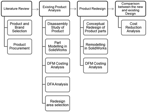
A brief overview of the general procedure for DFMA analysis is shown in Figure . The first step is to identify the product on which DFMA analysis will be performed. After selection, the product is then disassembled and individual parts are modelled in a CAD software. DFM costing analysis is carried out on the individual parts to set the baseline cost of the product design and DFA analysis is done to identify the candidates for elimination. Various redesign concepts are then brainstormed to reduce the part count and product cost. The redesigned parts are remodelled in the CAD software and a second round of DFM analysis is carried out. Finally, the costs and the DFA index of the original and redesigned product models are compared.
The remainder of the paper is divided into four sections. The second section provides a brief overview of the food processor product and its existing architecture. The third section highlights in detail the identified redesign opportunities in the product. The fourth section shows key results from DFA Analysis such as the DFA Index improvement and savings in assembly time. In the fifth section, the costs of the original and redesigned product models are compared to quantify the actual reduction in costs through DFMA implementation. Findings of this study is then summarized in the last section.
2. Food processor – a case study
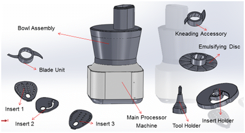
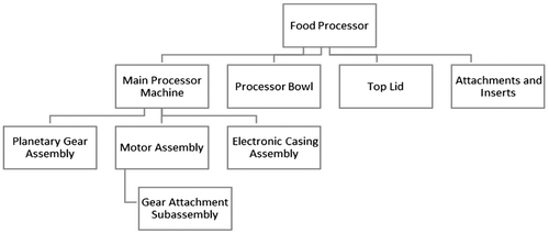
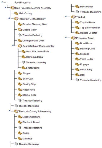
A food processor, as shown in Figure , is designed as a kitchen aid which can carry out a wide range of functions including chopping, slicing, mixing, grinding, granulating and fine slicing of various food materials. This product is a selected from a wide range of other products from a reputed consumer durable company. The food processor mainly consists of three parts; a main processor machine, a processor bowl and a top lid. It also consists of many miscellaneous parts like the feeder cup, inserts and other attachments. Figure shows the product architecture of the chosen product, and in Table an overview of the different food processor parts and their respective design which were modelled on a CAD Modelling Software (SolidWorks ® 2012) is also presented. The design of the existing product is analysed and detailed implementation of DFMA techniques is presented in the remaining sections of the paper.
Table 1. CAD modelling of food processor parts.
3. Redesign of the food processor
Being the first step of the DFMA analysis, existing assembly design was analysed with DFA analysis. In order to carry out DFA analysis, product structure was completely understood and studied. Using CAD Modelling and DFM Concurrent Costing software, the structure and assembly sequence of the existing product was documented. These details were fed into the DFA Product Simplification® 2015 software. For each part in the assembly sequence, the product function was analysed and the envelope dimensions, part weight, minimum part criteria and other insertion difficulties were evaluated. Generally, the maximum design efficiency improvement results from a reduction in the number of parts. To identify a candidate for elimination, there is a need to check whether the part in question satisfies the minimum part criteria. According to the minimum part criteria, for any separate part to exist, there can be only one of the following reasons: (1) the part forms the base of the product; (2) the part needs to be of a different material; (3) the part needs to move relative to other parts; (4) or the part is separately designed for ease of assembly. Any part not meeting the criteria is a candidate for elimination. The following redesign opportunities were identified during the study:
| (1) | Integration of Electronic Casing with Main Casing | ||||
| (2) | Replacement of Threaded Fasteners with Snap Fit Joint | ||||
| (3) | Overmoulding of Internal Gear, Top Lid Protrusion and Handle Locator | ||||
Redesign opportunities (1) and (2) were the most significant redesign opportunities as they eliminated the need for a separate part altogether. Every part requires separate manufacturing, documentation, inventory control and quality control strategy. Hence, eliminating a part in any design reduces the cost significantly. Redesign opportunities resulting purely from an ease of assembly perspective were comparatively less significant in the cost. Few DFA rule violations were identified in the existing design of the food processor. In the main casing design, fasteners were placed close to obstructions, the mounting boss was designed inside the main casing enclosure and the threaded fasteners were of different variety. Such rule violations could also lead to an increase in assembly time.
3.1. Integration of the electronic casing with the main casing
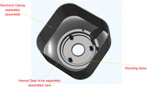
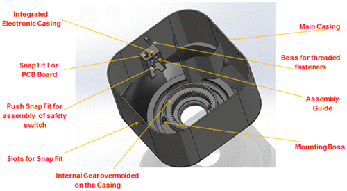
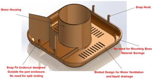
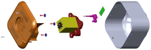
In the existing design of the food processor, the electronic casing and main processor machine casing were separate parts. The electronic casing part did not meet the minimum part criteria and was hence flagged as a candidate for elimination. The main casing was subsequently redesigned to accommodate this change. As shown in Figures and , the electronic casing is integrated with the main casing in the redesigned model whereas in case of the original model they are separate. Internal Gear on the other hand cannot be integrated directly with the main casing due to possible tooling issues. Therefore, overmoulding the internal gear over the main casing was considered to be a better redesign option. Overmoulding is an injection moulding process where one material is moulded over another material. Hence, this process eliminates the extra assembly cost of the separate part (internal gear).
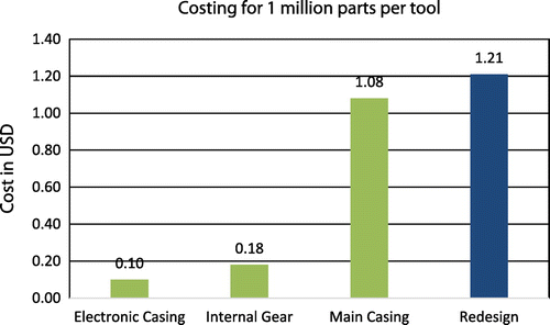
Figure shows the costing of the original and redesign models. In order to estimate the existing design cost, the manufacturing costs of the original main casing, electronic casing and internal gear were added individually. The total cost was USD 1.36 or INR 91.39 (1 INR = 0.015 USD). By comparison, the total cost of the redesign model was only USD 1.21 or INR 81.09. Hence, with the integration of the electronic casing and the internal gear, potential savings USD 0.15 (INR 10.3) could be achieved.
3.2. Replacement of threaded fasteners with snap fit joints
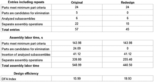
Snap fit joints provide many advantages over threaded joints like reduced assembly time and cost reduction (due to elimination of separate fasteners). By replacing the fasteners with snap fit joints, the number of separate assembly operations in the existing design was reduced from 22 to 15. This led to substantial assembly time savings of about 84 s. The number of threaded fastening operations for the back part of the main processor machine was reduced from 4 to 2, while the threaded fastening operation for assembly of PCB Board to the electronic casing was replaced by a snap fit joint. Figure shows the integration of snap fit joint to the back panel part.
To design a snap fit joint, the performance requirements and design constraints were identified. The design conditions for snap fit joint can be classified into two main categories: (1) Material Related (Yield Stress and Young’s Modulus of the Material); (2) Performance Related (Required Pull Out Force). Table articulates the design conditions for the back panel and electronic casing.
Table 2. Required design conditions for snap fit joint integration.
Raucent, Nederlandt, and Johnson (Citation1998) provided a design methodology for snap fit design. This methodology was adopted for designing the snap fit for back panel and the electronic casing. Using the design constraint: induced stress in the snap fit (Yield stress of the material/n), the mathematical condition for required minimum length was formulated as shown in Equation (Equation1(1) ).
(1)
In Equation (Equation1(1) ), H refers to the thickness of the cantilever beam (in mm) whereas Y0 refers to the undercut distance (in mm). As a thumb rule, Raucent et al. (Citation1998) mentioned that Y0 can be considered equal to H. For the second design constraint, Raucent et al. (Citation1998) used the static Coulomb Friction Law and the condition that the insertion force must be greater than the horizontal component of the contact force. Raucent et al. (Citation1998) combined the abovementioned conditions which resulted in the following equation:
(2)
In Equation (Equation3(3) ), K is the material factor:
(3)
α′ is the retaining angle for the snap fit joint and μ is the coefficient of friction. Typically, the value of μ is 0.6. Based on equation (Equation2(2) ), a suitable combination of α′ and Breadth (B) was selected to match the required Pull Out Force (P). Factor of safety of 1.2 was considered in design calculations. As the snap fits were designed at the edge of the wall, the snap fit thickness was considered to be equal to the wall thickness (Raucent et al. (Citation1998). Wall thickness of both the parts was 2.5 mm. (1 mm = 0.001 m). The final dimensions after design calculations are shown in Table .
Table 3. Final design dimensions of snap fit joints.
3.3. Overmoulding of top lid protrusion and handle locator
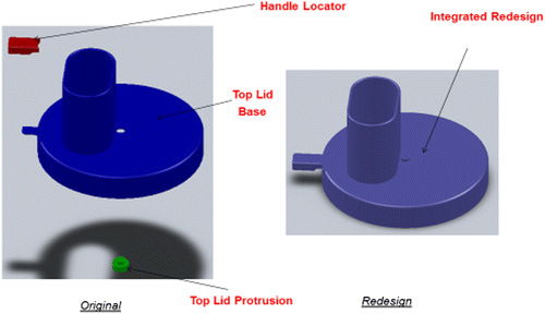
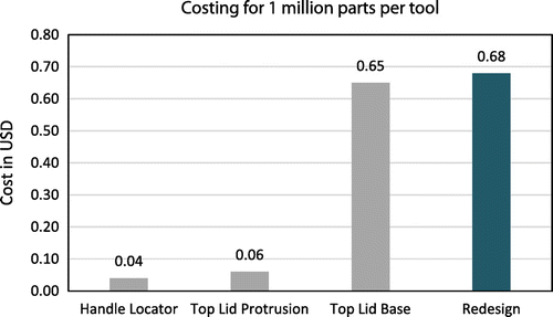
As shown in Figure , the top lid protrusion and handle locator were separate parts and it looked more as a requirement for aesthetics than for any practical function. The top lid protrusion can be integrated with the top lid itself as shown in Figure or it can be over moulded on the top lid thereby saving assembly time and maintaining the aesthetic look. Similar modifications can be done for the handle locator as well. Figure compares the costing of the original and redesign models. For the existing design, the cost was calculated by summing up the manufacturing costs of the top lid base, the top lid protrusion and the handle locator, resulting in the total of USD 0.75 (INR 50.32). The cost of the redesign model was USD 0.68 (INR 45.63). Therefore, potential cost savings of USD 0.08 (INR 5.37) could be achieved.
3.4. Comparison of original and redesign models in terms of product architecture
Figures and illustrate the difference between the original and redesign models of the main processor machine assembly. A significant improvement in the product architecture was evident as the total part count reduced from 57 to 45. The redesigned product architecture looked more compact due to the elimination of separate parts like electronic casing, screws and internal gear. By reducing the parts, it is very evident that the existing can be improved without losing the product quality and specification.
4. DFA analysis of the food processor
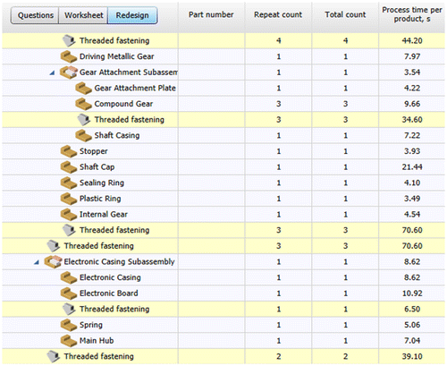
The first step for DFA analysis of the food processor was documentation of the assembly sequence of the product. Sequential disassembly of the product was carried out to study the order of assembly and related handling difficulties. The resulting assembly sequence of the product is shown in Figure . This assembly sequence was entered into the DFA Product Simplification ® Software 10.0. For each part, various parameters like item weight, envelope dimensions, part function, minimum part criteria, handling difficulties, alignment and vision difficulties were specified. This formed the information base from which the software generated reports on the possible candidates for elimination and DFA index. An average daily wage of USD 5.17 (INR 347.3) and 8-h work shift with 85% productivity was considered for labour costs calculation. These details were taken from the standard data available in http://www.tradingeconomics.com/india/ wages-in-manufacturing.
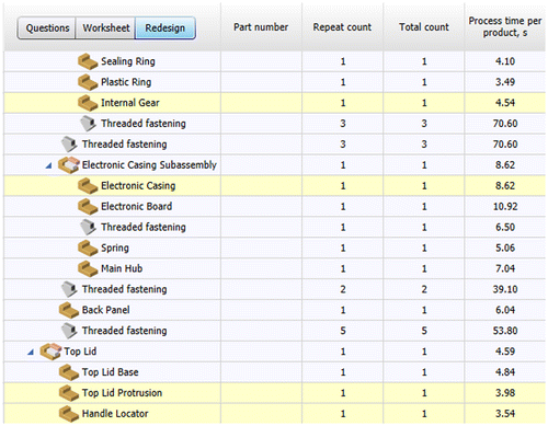
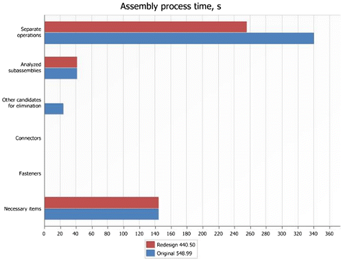
From the DFA report, different possible candidate elimination and the assembly time of the component/assembly level was identified. Figure shows the generated report highlighting the possible candidates for elimination while Figure illustrates the estimated assembly time at the component/assembly process level. The potential candidates for elimination were studied in detail one by one and several new redesign concepts were brainstormed to integrate these candidates with other existing parts. After converging to the best redesign concept, the new product profile of the redesign was created in software. The software then generated detailed reports comparing the models on the basis of assembly time, DFA index and part count. From Figure it can be observed that the threaded fastening operations consumed maximum time relative to other components and assembly processes. This justified the need to keep such operations to the minimum.
Figure gives an overview of the DFA (Design of Assembly) index improvement, the reduction in part count and the savings in assembly time. DFA index increased from 15.99 for the original design to 19.93 for the redesigned model. Assembly time savings of 108.49 s was achieved through the redesign of the product. An improvement in DFA index is an evidence of better design efficiency. DFA index measures the ratio of the ideal assembly time to the actual assembly time. The ideal assembly time takes into consideration the theoretical minimum number of parts required for the complete functionality of the product. DFA Index can be quantified as shown in Equation (Equation4(4) ):
(4)
(5)
In Equation (Equation5(5) ), Nm = Theoretical Minimum Number of Parts, Am = Theoretical Minimum Assembly Time per Part, Aa = Actual Assembly Time for the whole product.
In Figure , detailed breakdown of the assembly time savings is presented. It can be observed that majority of the assembly time savings result from the elimination of fasteners as the assembly time for these separate operations is very high. From Figure , it can be inferred that majority of the assembly cost savings are due to the elimination of fasteners as the assembly time for fasteners is relatively high.
5. Cost comparison analysis for original and redesign models
After exploring the individual redesign opportunities in detail, it is important to quantify the cost improvement for the product as a whole. This helps in understanding the full extent of cost reduction which can be achieved through the implementation of DFMA.
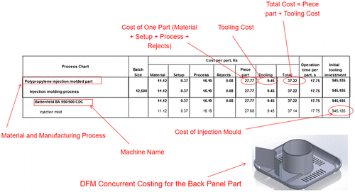
The cost modelling of the product (both original and redesign models) was done using the DFM Concurrent Costing ® Software 2014. The software required a number of parameters such as manufacturing process, material type, manufacturing machine, batch size and tool life. The manufacturing of plastic parts was done via the injection moulding process. This was determined by the presence of ejection pin marks on the surface of the parts. Ejection pin marks are a typical feature of injection moulding manufacturing process. A code indicating the type of plastic material used was embedded on the part surface. For example, PP stood for Polypropylene and ABS for Acrylonitrile Butadiene Styrene. This helped in determining the material of each part. The manufacturing machine was selected based on the clamping force requirement, dimensional constraints of the clamping unit and shot weight. The required clamping force was mainly dependent on part projected area and cavity pressure. Cavity pressure generally varies from 7 to 14 MPa (Rosato, Citation2003). Part projected area varies for each part. Accordingly, as per the projected area, part weight and dimensional constraints, the machine selection was done. Tool life of 100,000 parts per tool was considered. Figure shows the costing model for the back panel. The piece part cost, USD 0.41 (INR 27.77), included material, process, set-up and rejects costs. Further, the tooling cost of the part, amortized over the tool life (100,000 parts per tool), was added to give the total cost of USD 0.55 (INR 37.22). Cost models for other parts were also generated in the same manner and were added to calculate the total cost of the whole product. The report showed the various parameters considered for modelling along with the piece part cost and the total cost of the back panel (Costs are in Indian Rupee: INR). For the cost comparison, every component of the food processor was evaluated in DFM Concurrent Costing Software and using this information the total costs for both existing and the redesigned model are reported.
For the food processor product as a whole, a total savings of USD 0.25 (INR 16.79) was achieved with this study. Assembly cost savings of USD 0.02 (INR 1.53) was achieved. Final estimated manufacturing cost of food processor was calculated to be USD 15.7 (INR 1054.25). Majority of the cost reduction was seen in the main processor machine assembly category. Integration of the electronic casing and internal gear to the main casing was the most significant factor in improving the cost effectiveness of the product. Substantial cost improvement was seen in this category because elimination of any part from a product obviates the need for tooling, process and assembly of that part altogether. Moreover, every part calls for documentation and inventory management. Such overhead costs are also eliminated. In the assembly costs category, it is observed that majority of the savings are due to the integration of snap fit joint to the back panel and main casing (for PCB board assembly). The assembly time for threaded fastening operations is very high and use of snap fits obviates the need for handling, orientation and assembly of threaded fasteners. In the top lid assembly, significant cost reduction can be observed with a very simple change in design (integration of top lid protrusion with the top lid base). This validates the view that part elimination opportunities, no matter how simple they may seem, can lead to substantial savings in manufacturing costs. Table shows an overview of cost-reduction analysis highlighting the major cost components.
Table 4. Cost comparison of original and redesign models.
6. Conclusion
This paper illustrates the various DFMA considerations in the design of a existing consumer product used in the Indian market. Detailed suggestion for improving the design and assembly of the product is presented in this paper. Using the DFMA methodology, an increase in DFA index from 15.99 to 19.93 was reported. Overall cost savings of 0.25 USD (INR 16.79) and assembly time savings of 108.49 s was achieved. Maximum cost reduction (0.15 USD) was observed in the main processor machine sub-assembly. Majority of the assembly cost savings were due to the elimination of threaded fasteners and a majority of manufacturing cost reduction was due to integration of electronic casing and main casing.
Although, the cost reduction is equivalent to only 1.59% of the total product cost, this can be significant for consumer product companies which manufacture these products at low-profit margins and produces in large batches. Financially, these extra savings in cost per product can boost the profitability of the company. Moreover, consumer products like food processors are manufactured on a large scale and the cumulative cost savings to the company can be very significant. In addition, companies may even choose to pass on this cost benefit to end users thereby gaining a competitive edge against other market players. However, to realize the benefits of DFMA, companies will need to overhaul their entire design process by bringing manufacturing and design teams together. This can be a herculean task to carry out, especially for large companies. Today, many companies are inclined towards reducing their carbon footprint to fight climate change. DFMA methodology in conjunction with Design for Environment (DFE) guidelines can be a powerful way to reduce the cost of products in a sustainable manner. To quantify the impact of following DFE guidelines, sustainability analysis along with cost–benefit analysis of the original and redesigned product models can be carried out in the future study. Cost vs. sustainability comparison can also help industries for better understanding of the trade-off between cost and environmental benefits of a product design.
Disclosure statement
No potential conflict of interest was reported by the authors.
References
- Anil, M., Kurain, J., & Arsha, J. D. (2013). Design for manufacturing and assembly of a connecting rod. International Journal of Advanced Research in Mechanical and Production Engineering and Development, 1, 12–18.
- Annamalai, K., Naiju, C., Karthik, S., & Prashanth, M. M. (2013). Early cost estimate of product during design stage using design for manufacturing and assembly (DFMA) principles. Paper presented at the advanced materials research, 2012 3rd International conference on manufacturing science and technology, ICMST 2012 (Vol. 622, pp. 540–544), New Delhi, India.
- Boothroyd, G. (1994). Product design for manufacture and assembly. Computer-Aided Design, 26, 505–520.10.1016/0010-4485(94)90082-5
- Boothroyd, G., Dewhurst, P., & Knight, W. A. (2010). Product design for manufacture and assembly. Boca Raton, FL: CRC Press.
- Canciglieri Jr., O., Kovalchuk, J. P. B., Rudek, M., & de Souza, T. M. (2010). Development of white goods parts in a concurrent engineering environment based on DFM/DFA concepts. In J. Pokojski, S. Fukuda, & J. Salwiński (Eds.), New world situation: New directions in concurrent engineering (pp. 491–501). London: Springer.
- Eskelinen, H., & Ström, J.-P. (2007). DFM (A)-Aspects of an Advanced Cable Gland Design. In Tutkimusraportti/Research report-Lappeenrannan teknillinen yliopisto, Teknillinen tiedekunta, Konetekniikan osasto ( Research Report 73/2008). Faculty of Technology, Department of Mechanical Engineering, Lappeenranta University of Technology. ISBN 978-952-214-450-8 (PDF), ISSN .
- Estorilio, C., & Simião, M. C. (2006). Cost reduction of a diesel engine using the DFMA method. Product Management & Development, 4, 95–103.
- Isanaka, S. P., Sparks, T. E., Liou, F. F., & Newkirk, J. W. (2016). Design strategy for reducing manufacturing and assembly complexity of air-breathing Proton Exchange Membrane Fuel Cells (PEMFC). Journal of Manufacturing Systems, 38, 165–171.10.1016/j.jmsy.2015.10.004
- Krumenauer, F., Matayoshi, C., da Silva, I., & Batalha, G. (2008). Concurrent engineering and DFMA approaches on the development of automotive panels and doors. Journal of Achievements in Materials and Manufacturing Engineering, 31, 690–698.
- Meeker, D., & Rousmaniere, A. (1996). DFMA and its role in the integrated product development process. Retrieved from http://web.mit.edu/meeker/Public/DFMAandIPDP.pdf
- Priti, A. (2002). Consumer durables industry – Surviving the slowdown. Retrieved from http://www.crisil.com/Ratings/Commentary/CommentaryDocs/consumerdurables0302.pdf
- Raucent, B., Nederlandt, C., & Johnson, D. (1998). Plastic snapfit fastener design. The International Journal of Advanced Manufacturing Technology, 14, 185–198.10.1007/BF01188414
- Rosato, D. V. (2003). Plastics engineered product design. Oxford: Elsevier.
- Schmidt, S. (1998). Preventive optimisation of costs and quality for the total life cycle-design for manufacture, assembly, service, environment (DFMA). In Society of Automotive Engineers (SAE) (HRSG): Total Life Cycle Conference Proceedings (Graz 1998) (pp. 49–56). Warrendale: SAE. doi:10.4271/982166
- Selvaraj, P., Radhakrishnan, P., & Adithan, M. (2009). An integrated approach to design for manufacturing and assembly based on reduction of product development time and cost. The International Journal of Advanced Manufacturing Technology, 42, 13–29.10.1007/s00170-008-1580-8
- Suresh, P., Ramabalan, S., & Natarajan, U. (2016). Integration of DFE and DFMA for the sustainable development of an automotive component. International Journal of Sustainable Engineering, 9, 107–118.10.1080/19397038.2015.1096313
- Tucci, M., De Carlo, F., Borgia, O., & Fanciullacci, N. (2014). Accelerated life tests as an integrated methodology for product design, qualification and production control: a case study in household appliances. Production & Manufacturing Research, 2, 112–127.

