
 ?Mathematical formulae have been encoded as MathML and are displayed in this HTML version using MathJax in order to improve their display. Uncheck the box to turn MathJax off. This feature requires Javascript. Click on a formula to zoom.
ABSTRACT
In the present study, the capability of spark plasma sintering (SPS) in a semi-solid regime to produce AZ91D/SiCp composites, prepared by mechanical milling (MM), was investigated. An SPS process was used to densify AZ91D/SiCp composite powders by heating them to a semi-solid temperature of 497°C or 516°C, at a heating rate, holding time and pressure of 50 °C/min, 1 min and 40 MPa, respectively. In preparing the requisite powders, MM was used as an effective recycling method to prevent excessive consumption of energy and raw materials while converting magnesium alloy chips into powder in a planetary ball mill. The simultaneous effects of milling parameters (time and ball-to-powder weight ratio (BPRs)) on the MM powder were investigated by FESEM and PSA. Mechanical alloying (MA) of the milled powder with 40 wt% −2 µm SiC and characterization of the obtained powder by OM and PSA were also carried out. The phase compositions of the powder and sintered samples were analyzed by XRD. The microstructure, density, hardness and compressive strength of the sintered samples were also studied. The results show that composites with few porosities and good mechanical properties were prepared by SPS in a semi-solid regime.
1. Introduction
Semi-solid metal (SSM) processing is a relatively new forming technology that provides several important advantages, such as better die-filling, longer die life, shorter solidification time, less air entrapment and reduced shrinkage [Citation1]. In semi-solid bulk formation, the dendritic microstructures of feedstock materials must be broken down. Replacing the bulk material with powdered material through semi-solid powder processing (SPP) combines the advantages of semi-solid forming and powder metallurgy, contributing to the formation of complex shapes. It also enables mixing of various particles for improved composite properties and eliminates post-processing steps required in powder metallurgy processes. The steps involved in SPP are powder preparation, pre-compaction at room temperature, material heating to a semi-solid state and densification. SPP has been applied to produce net-shaped MMCs with promising microstructures at low cost with high efficiency and good compositional control. Guo and Tsao [Citation2] studied the tribological behavior of Al/SiC/graphite composites with various amounts of graphite addition synthesized by the semi-solid powder densification (SSPD) method. They found that the hardness and CTE of the composites both decreased with increases in the amount of graphite. Li et al. [Citation3] determined the solidification behavior of semi-solid slurry with a solid fraction beyond 0.6 in Pb–15 wt% Sn alloy. They succeeded in producing a single-crystal powder coated with Pb–Sn eutectic during continuous stirring and cooling processes. Javdani et al. [Citation4] fabricated Al7075/Al2O3 composites by blending different sizes and weight fractions of Al2O3 particles with matrix particles using a planetary ball mill and then compacting them to a semi-solid state under different pressures. Increasing the size of the reinforcing particles and applied pressure resulted in increased density and hardness.
Efforts to produce metal and composite powders with high mechanical and physical properties have included different methods, such as centrifugal atomization [Citation5], water atomization [Citation6], chemical vapor deposition (CVD) [Citation7] and mechanical milling/alloying (MM/MA) [Citation8–Citation10]. MM has been significant alternative to other production methods for preparing powders with a broad range of compositions and structures in recent years. Fabrication of powders from recycled chips by MM is also a novel processing technique. Oginuma and Yuasa [Citation11] used machined AZ31 alloy chips to make Mg-Zn and Mg-Al-Zn powder mixtures by mechanical alloying for various milling times in a planetary ball mill. MM of recycled Mg chips was conducted by Thein et al. [Citation12] to produce Mg–5wt% Al reinforced with xwt% (x = 1, 2 and 5) AlN composite powder. Susniak et al. [Citation13] successfully obtained AlSi5Cu2/SiC nanocrystalline composite powder by mechanical alloying (MA) of AlSi5Cu2 chips with reinforcement by 0, 10, 15, 20 wt% of silicon carbide.
AZ91D magnesium alloy has widespread uses in the automobile, communications and aerospace industries due to its good combination of mechanical and corrosion properties compared to other Mg-based alloys. Among ceramic reinforcements also used in Mg MMC, silicon carbide particles (SiCp) are the most popular due to their high stability and wettability in the Mg matrix [Citation14]. In this paper, the capability of spark plasma sintering (SPS) in a semi-solid regime to produce AZ91D/SiCp composites, prepared by MM, was investigated. Because of the technological importance of magnesium and its alloys and the need for recycling chips for industrial and environmental reasons, MM of magnesium alloy chips and MA of milled powder with 40 wt% SiCp were conducted in a planetary ball mill, and the obtained powders were investigated by OM, FESEM, PSA and XRD. The prepared composite powder was compacted in the semi-solid regime by SPS, and the microstructure, density, hardness and compressive strength of the sintered samples were studied.
2. Experimental procedures
2.1. Materials
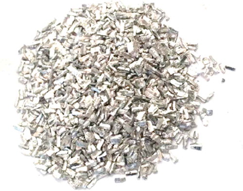
Magnesium AZ91D alloy chips provided by the Rongsheng Metal Group and machined using a milling machine with a mean size of 4 2
1 (mm) were used in this study for conversion into powder by planetary ball milling. Lubricating oil was used to prevent ignition of the chips during machining, and the chips were washed after the machining operation. An image of these chips is displayed in . The chemical composition of this alloy, as determined using inductively coupled plasma-optical emission spectroscopy (ICP-OES), is given in . The size and weight fraction of the alpha silicon carbide (
-SiC) powder used as reinforcement are 2 µm and 40%, respectively.
Table 1. Chemical composition of magnesium AZ91D alloy (wt%).
Figure 1. Magnesium AZ91D alloy machining chips.
2.2. Preparation of the powders
MM and MA processes were carried out at room temperature using a NARYA-MPM 2*250 H planetary ball mill with two 250-ml steel vials. To prevent the chips and powders from oxidizing during the MM and MA processes, the vials were filled with high-purity argon gas. Stearic acid was added as a process control agent (PCA) to decrease agglomeration. The mill was cooled continuously by a fan and also stopped periodically (for 15 min every 15 min) to prevent excessive cold welding and overheating. The conditions of the MM and MA processes are given in . The AZ91D chips were milled at three different ball-to-powder weight ratios (BPRs) and times: BPR of 25:1 for 10 h, BPR of 20:1 for 15 h and BPR of 15:1 for 20 h; and the simultaneous effects of the milling parameters on the milled powder were investigated.
Table 2. Conditions of MM and MA processes.
The milled powder was passed through a 140-mesh sieve. Then, the obtained powder, combined with 2 m SiC were used as the starting material for the MA of AZ91D–40 wt% SiC powder at a BPR of 20:1 for 5 h. Investigations of the morphology, microstructure and dispersion characteristics of MM and MA powders were carried out using OLYMPUS optical microscopes (OM) and a HITACHI S-4160 field emission scanning electron microscope (FESEM). The size distributions of the powders were quantified using a laser particle size analyzer (Fritsch, model ‘ANALYSETTE 22 NanoTec’). The phase analysis was evaluated by X-ray diffractometry (XRD) (Siemens D-500) using Cu K
radiation (1.54 Å), at 25 mA and 30 kV. The XRD patterns were recorded at room temperature with a step size of 0.02° and a time per step of 0.5 s over an angular range of 20–80° 2
. The XRD patterns of the MM and MA powders were compared with each other.
2.3. Sintering in the semi-solid state
An SPS 60–10 apparatus made at Malek Ashtar University of Technology was used to carry out SPS in the semi-solid regime. Unlike other powder metallurgy processes, no pre-compaction step is required for SPS. The prepared composite powder was poured into a graphite die with a diameter of 10 mm and heated to a semi-solid temperature of 497°C or 516°C at a heating rate of about 50°C/min, when the holding time was 1 min. The sintering process was performed in a vacuum. A pressure of approximately 40 MPa was applied from the beginning of sintering. The temperature was measured by means of a thermocouple in the center of the die. The samples sintered by SPS had an approximately 10 mm diameter and 10 mm height. Analyses of the microstructure and phase composition of the samples were carried out using FESEM and XRD. Their densities were measured by immersion in distilled water based on the Alchimedes principle. The mechanical properties of the sintered samples were evaluated by the Vickers hardness test (HV) using an ESEWAY hardness tester and applying a 10 kg load for 10 s; and also by a compression test using a SANTAM STM-50 universal testing machine at a strain rate of 2 × 10⁻³ s−1.
3. Results and discussion
3.1. Effect of MM and MA on powder characteristics
shows images of the initial chips and the chips after 20 h milling at a BPR of 15:1. As can be seen, there is no clear change in the size of the chips, except that some of them have been broken. FESEM images of changes in the morphology of the chips after 15 and 10 h milling at a BPR of 20:1 and BPR of 25:1, respectively, are displayed in . Mechanically milled AZ91D particles exhibit a flake-like shape such that small particles are coupled with large ones. During milling, the flakes are welded together to form large particles. With continuation of the process, work-hardening of the particles and impact exerted on them cause the large particles to fracture and form smaller ones with irregular shapes. At a higher BPR, the time required is shorter. The number of collisions per time unit increases with increases in the weight percentage of the balls, and more energy is consequently transferred to the powder particles, speeding up the milling and alloying processes [Citation15]. Comparison of the two FESEM images in shows that a smaller particle size can be achieved by choosing a high BPR and short time rather than a low BPR and long time.
Figure 2. (a) Unmilled chips and (b) chips after 20 h of milling at a BPR of 15:1.
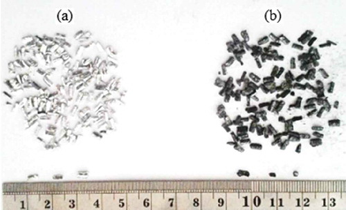
Figure 3. FESEM images of AZ91D magnesium alloy powders: (a) after 10 h of milling at a BPR of 25:1 and (b) after 15 h of milling at a BPR of 20:1.
Particle size distribution curves of powders obtained by the MM process are also displayed in . D50 and D90-D10 are minimum diameters equivalent to 50% of the particles and the extent of the size distribution, respectively. As seen in ) as compared with ), with an increase of 25% in BPR and a reduction of 33% in time, the value of D50 shows a reduction of 66%. The extent of the size distribution is also narrower at 41%. Materials with similar, narrower distributions are less prone to segregation. Powders with a narrow size distribution are preferable to monosized powders or powders with a broad size distribution due to the improved sinterability and high-reliability microstructural control of the powder compacts [Citation16]. As a general conclusion, powder with a smaller particle size and narrower size distribution can be obtained at shorter milling times by choosing a higher BPR.
Figure 4. Particle size distribution curves of powder obtained: (a) after 10 h of milling with a BPR 25:1 and (b) after 15 h of milling with a BPR 20:1.
After milling of the chips at a BPR of 25:1 for 10–30 h, the milled powder was passed through a 140-mesh sieve and mechanically alloyed with 40 wt% (27 vol. %) −2 µm SiC at a BPR of 20:1 for 5 h. OM images of SiC particles of MM powder after sieving and of MA powder are shown in . SiC particles have irregular shapes with sharp angles ()). Mechanically milled 140-mesh AZ91D particles had been flattened to form flaky-shaped particles ()). ) shows a relatively homogeneous distribution of SiC particles in the magnesium alloy matrix obtained by the MA process after 5 h. The high-energy MA technique reduces the reinforcement size and eliminates reinforcement defects and sharp edges, producing a rounder morphology of reinforcement, which results in better composite properties [Citation17]. The particle size distribution curve of MA powder is illustrated in . As seen, a small particle size and narrow size distribution were obtained after MA processing.
Figure 5. OM images of: (a) SiC particles, (b) MM powder (AZ91D) after sieving and (c) MA powder (AZ91D/40 wt% SiC).
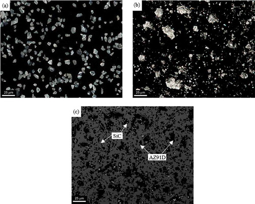
Figure 6. Particle size distribution curve of AZ91D/40 wt% SiC powder obtained after 5 h of alloying at a BPR of 20:1.
XRD profiles of MM AZ91D powder and of MA powder revealed the presence of the -Mg phase and
-Al12Mg17 phase and the reinforcement SiC (). MM caused peak broadening as a result of a decrease in crystal grain size and increase in lattice micro-strain at the crystallite boundaries that caused an increase in hardness (see the increasing of peak width of the AZ91D alloy phases after 5 h MA). No new peaks appeared with the MM processing. A trace of the Mg2Si phase was detected after MA processing. There are basically two possible reactions for formation of the Mg2Si phase:
Figure 7. XRD patterns of (a) MM AZ91D powder and (b) MA composite powder.
In the case of Reaction 2, MgO is the other possible reaction product, whose peak was not detected in the XRD results.
3.2. Investigation of sintered samples
AZ91D/40 wt%-2 µm SiC composite powder was densified using an SPS process in a semi-solid regime. The Scheil equation gives the liquid fraction at any temperature
within the solidification range, assuming that homogenization of the liquid is complete:
where is the melting temperature of the pure metal,
is the liquidus temperature of the alloy, and
is the equilibrium distribution coefficient. Differential scanning calorimetry analysis was performed on AZ91D chips using a METTLER TOLEDO DSC in nitrogen-controlled environment, and the values of 650°C for
, 595°C for
and 0.36 for
were obtained. Two sintering temperatures in a semi-solid state were chosen: 497°C (AZ91D liquid fraction of 15%) and 516°C (AZ91D liquid fraction of 20%). The applied pressure and holding time were 40 MPa and 1 min, respectively. SPP can fabricate fully densified composites with relatively low pressure [Citation18].
shows FESEM images and EDS mapping of the AZ91D/SiCp composites. As can be seen, there are a few porosities in the microstructure. The experimental density, apparent porosity and HV of the composite samples are given in . The experimental densities of both sintered samples are greater than their theoretical density (2.19 g/cm3). This may be because of an increase in the Fe content of composite powder during MA processing. The results of ICP-OES testing show that the Fe weight percentage in MA composite powder reached 2.1%, while the percentages of that in AZ91D chips and reinforced SiC particles are 0.003% and 0.3%, respectively. This indicates that a longer milling time and higher energy led to a higher vial and ball wear rate [Citation19,Citation20]. Fortunately, metallic powders can easily coat the surfaces of milling balls and the inner walls of vials; thus, this coating may decrease the contamination level by preventing the milling medium from contacting the milled powders [Citation21]. The hardnesses of the sintered samples are higher than AZ91D hardness, which is about 71 HV. When the sintering temperature increased from 497°C to 516°C, the hardness was reduced from 157 HV to 148 HV, although the opposite result might have been expected. The probable phenomenon responsible is relaxation of the lattice strains and, finally, degradation of the hardness at high temperatures. shows stress–strain curves of the sintered samples under compression at room temperature. The ultimate compressive strengths of samples sintered at T = 497°C and T = 516°C are 266 MPa and 261 MPa, respectively, while that of AZ91D alloy is 288 MPa. This shows that SiC particles caused a small decrease in the compressive strength of composite samples. The stress–strain curves also confirm the relaxation of the lattice strains in a sample sintered at 516°C. shows XRD profiles of the sintered samples. Except for MgO peaks (noted (✶)), no new peaks appeared in the course of the sintering process.
Table 3. Experimental density, apparent porosity and Vickers hardness of the composite samples.
Figure 8. FESEM images and EDS analyses of AZ91D/40 wt% SiC composites. Top row, sintering at 497°C: (a) FESEM image, (b) element mapping image of Mg and (c) element mapping image of Si; Bottom row, sintering at 516°C: (d) FESEM image, (e) element mapping image of Mg and (f) element mapping image of Si.
Figure 9. Engineering stress–strain curves obtained during compression at a strain rate of 2 × 10⁻³ s−1.
Figure 10. XRD patterns of samples sintered at (a) 497°C and (b) 516°C.
4. Conclusion
In this paper, MM of AZ91D chips, MA of the obtained powders with 40 wt% −2 µm SiCp reinforcement and SPS of composite powder prepared in a semi-solid regime were conducted, and the following conclusions were drawn:
In MM, choosing a higher BPR enables powder with a smaller particle size and narrower size distribution to be obtained with shorter milling times. The optimum MM powder was achieved at a BPR of 25:1 and 10 h milling.
A homogenous distribution of the 40 wt% −2 µm SiCp reinforcement phase in an AZ91D matrix was successfully prepared using the MA process. A trace of the Mg2Si phase was detected by XRD after MA processing.
AZ91D/40 wt% SiC composites with few porosities were obtained by SPS at two sintering temperatures in the semi-solid state, namely 497°C (AZ91D liquid fraction of 15%) and 516°C (AZ91D liquid fraction of 20%), when the applied pressure and holding time were 40 MPa and 1 min, respectively.
The experimental densities of both sintered samples are higher than their theoretical density of them. This is because of an increase in the Fe content of composite powder during MA processing due to an intensification of the vial and ball wear rate with increases in the milling time and energy.
Increasing the sintering temperature from 497°C to 516°C reduced the hardness from 157 HV to 148 HV. This may be due to a relaxation of the lattice strains and, finally, a degradation of the hardness at high temperatures. The obtained stress–strain curves also confirm this possibility.
XRD profiles of the sintered samples show that, except for MgO peaks, no new peaks appeared in the sintering process.
Disclosure statement
No potential conflict of interest was reported by the authors.
References
- Hirt G, Kopp R, editors. Thixoforming: semi-solid metal processing. Weinheim: John Wiley & Sons; 2009.
- Guo MT, Tsao CY. Tribological behavior of self-lubricating aluminium/SiC/graphite hybrid composites synthesized by the semi-solid powder-densification method. Compos Sci Technol. 2000;60:65–74.
- Li T, Lin X, Huang W. Preparation of metal alloy powder by semi-solid processing. J Mater Sci. 2007;42:2669–2674.
- Javdani A, Pouyafar V, Ameli A, et al. Blended powder semisolid forming of Al7075/Al2O3 composites: investigation of microstructure and mechanical properties. Mater Des. 2016;109:57–67.
- Plookphol T, Wisutmethangoon S, Gonsrang S. Influence of process parameters on SAC305 lead-free solder powder produced by centrifugal atomization. Powder Technol. 2011;214:506–512.
- Liu Y, Niu S, Li F, et al. Preparation of amorphous Fe-based magnetic powder by water atomization. Powder Technol. 2011;213:36–40.
- Kim KH, Lee YB, Choi EY, et al. Synthesis of nickel powders from various aqueous media through chemical reduction method. Mater Chem Phys. 2004;86:420–424.
- Varol T, Canakci A. Effect of weight percentage and particle size of B4C reinforcement on physical and mechanical properties of powder metallurgy Al2024- B4C composites. Met Mater Int. 2013;19:1227–1234.
- Canakci A, Erdemir F, Varol T, et al. Determining the effect of process parameters on particle size in mechanical milling using the Taguchi method: measurement and analysis. Measurement. 2013;46:3532–3540.
- Canakci A, Varol T, Ozsahin S. Analysis of the effect of a new process control agent technique on the mechanical milling process using a neural network model: measurement and modeling. Measurement. 2013;46:1818–1827.
- Oginuma H, Yuasa E. Crystal structure formed in mechanical alloying process of Mg-Al-Zn powder mixture using magnesium alloy machined chips. JSME Int J Ser A Solid Mech Mater Eng. 2005;48:381–386.
- Thein MA, Lu L, Lai MO. Effect of milling and reinforcement on mechanical properties of nanostructured magnesium composite. J Mater Process Technol. 2009;209:4439–4443.
- Suśniak M, Pałka P, Karwan-Baczewska J. Influence of milling time on the crystallite size of AlSi5Cu2/SiC composite powder. Arch Metall Mater. 2016;61:977–980.
- Viswanath A, Dieringa H, Kumar KA, et al. Investigation on mechanical properties and creep behavior of stir cast AZ91-SiCp composites. J Magnesium Alloys. 2015;3:16–22.
- Suryanarayana C. Mechanical alloying and milling. Prog Mater Sci. 2001;46:1–84.
- Ma J, Lim LC. Effect of particle size distribution on sintering of agglomerate-free submicron alumina powder compacts. J Eur Ceram Soc. 2002;22:2197–2208.
- Fogagnolo JB, Velasco F, Robert MH, et al. Effect of mechanical alloying on the morphology, microstructure and properties of aluminium matrix composite powders. Mater Sci Eng A. 2003;342:131–143.
- Wu Y. Fabrication of metal matrix composite by semi-solid powder processing [dissertation]. Ames (Iowa): State University of Iowa at Ames; 2011.
- Keneshloo M, Paidar M, Taheri M. Role of SiC ceramic particles on the physical and mechanical properties of Al–4% Cu metal matrix composite fabricated via mechanical alloying. J Compos Mater. 2017;51:1285–1298.
- Zakeri M, Ramezani M, Nazari A. Effect of ball to powder weight ratio on the mechanochemical synthesis of MoSi2-TiC nanocomposite powder. Mater Res. 2012;15:891–897.
- Luo XT, Li CJ, Yang GJ. Correlations between milling conditions and iron contamination, microstructure and hardness of mechanically alloyed cubic BN particle reinforced NiCrAl matrix composite powders. J Alloys Compd. 2013;548:180–187.