
 ?Mathematical formulae have been encoded as MathML and are displayed in this HTML version using MathJax in order to improve their display. Uncheck the box to turn MathJax off. This feature requires Javascript. Click on a formula to zoom.
ABSTRACT
In this study, a (Ti + graphite)-Ni composite powder serving as a coating material was deposited on H13 steel to fabricate an in-situ TiC-reinforced Ni-based composite coating by a new type of ESD process, which was named ultrasonic-assisted electrospark powder deposition (UEPD). The composite coating has an average thickness of approximately 45.5 μm and metallurgically bonds with the substrate. The ultrasonic vibration exerted on the UEPD electrode can effectively improve the forming quality of the composite coating, which produces better compactness and thickness uniformity as well as few defects. The microstructure mainly consisted of submicron dendrites due to the rapid solidification of the molten pool. TiC particles as reinforcements were successfully synthesized in the coating via an in-situ reaction due to their low Gibbs free energy and high melting point. The formation of refined grains and in-situ reinforcements prompts the average hardness of the coating to reach 1400.5 HV0.05, which is approximately 2.5 times that of the substrate. The tribological properties of the composite coating are greatly improved in comparison with those of the substrate. The wear rate and friction coefficient of the composite coating decrease by two orders of magnitude and 46.2%, respectively.
1. Introduction
The electrospark deposition (ESD) process is a promising and widely investigated method for the performance enhancement of mechanical parts and tools in the industry [Citation1]. Compared to other coating technologies, the ESD process and its coating have some unique characteristics, such as simple implementation, nonpollution, cost effectiveness, low thermal impact and high adhesion [Citation1,Citation2]. In addition to preparations of the various functional coatings, the repair of the damage to heterogeneous surfaces is a great advantage of the ESD process, especially in the treatment of heat-sensitive alloys, such as aluminum, magnesium, titanium or heat-treated steel [Citation3,Citation4].
Cermet successfully combines the advantages of metals and ceramics, such as high hardness, good stiffness, and excellent chemical and mechanical stability, and thus is widely applied as coatings [Citation5,Citation6]. In previous studies, ceramic particles have been introduced into Ni-, Co-, or Fe-based alloys to fabricate various composite coatings of cermet [Citation6–8]. Generally, the introduction of ceramic particles into composite coatings is performed in two ways, i.e. direct addition or in-situ synthesis. The mode of direct addition is the conventional production route of composite coatings by the ESD process. However, this mode often introduces poor wettability and weak bondability between ceramic particles and the metal matrix as well as segregation of reinforcements [Citation9]. In contrast, the in-situ synthesis of ceramic particles has advantages of homogeneous distribution, strong bondability, high density and flexible design [Citation10,Citation11], which can bring better quality and performance to the composite coating. To date, many surface techniques have been employed to prepare in-situ composite coatings, such as laser cladding, thermal spraying, and plasma transferred arc (PTA) cladding [Citation12–14].
However, in-situ synthesis of composite coatings via ESD is still a challenge. Very few studies have been published on the in-situ generation of ceramics by ESD. The limited number of studies is mainly attributed to the complex principle of ESD. The principle of the ESD process is to deposit electrode materials on a metal substrate by high-frequency electrospark discharge, which is similar to a pulsed microwelding technique [Citation15,Citation16]. Therefore, for the conventional ESD process, the coating materials need to first be prefabricated as a tool electrode. Powder metallurgy and self-propagating high-temperature synthesis (SHS) are the most common methods for the prefabrication of tool electrodes, which all need to be implemented at high temperature [Citation17,Citation18]. However, this process leads to the premature occurrence of in-situ reactions at the prefabrication stage of the tool electrode rather than the forming stage of the coating [Citation19].
In a previous investigation, we proposed a new type of ESD process, ultrasonic-assisted electrospark powder deposition (UEPD), which adopts a glue joint method to connect the composite powder on the copper plate as the discharge and deposition material [Citation3]. Compared to the conventional ESD process, the UEPD process not only simplifies technological processes but also prevents the high-temperature synthesis of the electrode tool. This provides feasibility to fabricate in-situ composite coatings. In this study, the UEPD process was used to fabricate an in-situ TiC-reinforced Ni-based (TiC-Ni) composite coating on H13 steel. TiC particles have high hardness, good wettability and low density and are commonly used to enhance the wear resistance of composite coatings [Citation20]. In addition, because Ti is a strong carbide-forming element, TiC can be more easily synthesized by an in-situ reaction. Therefore, TiC is usually the preferred reinforcement for in-situ composite coatings. However, in-situ TiC-reinforced composite coatings prepared by the ESD process have rarely been reported. The investigation involves not only the surface morphology, microstructure, hardness but also the tribological properties. Moreover, the formation mechanism of UEPD coating and the in-situ TiC particles is discussed in detail. To more intuitively describe the effect of ultrasonic vibration on the forming process of the coating, an electrospark powder deposition (EPD) coating without ultrasonic assistance was studied.
2. Experimental procedure
2.1. Materials
In this study, a hot-work die steel of brand H13 was used as the substrate with a size of 50 × 30 × 8 mm3, and its chemical components are shown in . Before the experiment, the H13 steel was heat-treated by 1000°C quenching + 550°C tempering to improve its mechanical properties. The electrode tool was mainly composed of an electrode core and composite powder. The electrode core was a 15 × 60 × 2 mm3 copper sheet, polished to Ra 3.2 by abrasive paper. The composite powder was the source material of the deposition coating. Functionally, it can be divided into two parts, i.e. the Ni-base powder was the matrix of the coating, and the mixed (Ti + graphite) powder was used as the in-situ synthesis component. The Ni-based powder adopted a commercially available NiCrSiB self-fluxing alloy powder, and the chemical composition is shown in . The molar ratio of Ti to graphite was 1:1, and their total mass accounted for 20% in the composite powder. Moreover, a commercially available adhesive composed of Ag powder and resin (mass ratio 1:1) was used to bond the electrode core and the composite powder, which was beneficial for bonding and conductivity.
Table 1. Chemical composition of H13 steel and NiCrSiB alloy powder (wt.%).
2.2. Preparation process and parameters
The fabrication process of the UEPD coating involves UEPD electrode preparation and UEPD machining, as shown in .
Figure 1. Schematic diagram of the fabrication process of UEPD coatings: (a) the UEPD electrode preparation; (b) the process of UEPD machining.
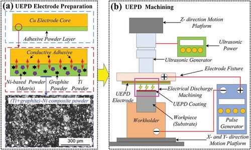
First, the Ag-containing conductive adhesive was uniformly sprayed on the electrode core surface with a thickness of approximately 0.05 mm; then, the (Ti+graphite)-Ni composite powder was evenly covered on this conductive adhesive layer, compacted and controlled to a total thickness of approximately 0.2 mm. After adhesive solidification, the UEPD electrode could be obtained, as shown in . Second, the UEPD electrode and substrate were fixed onto the ultrasonic generator and the workholder, respectively. Driven by the Z-directional motion platform, the UEPD electrode gradually moved toward the substrate. When the distance between the tool electrode and the surface of the workpiece reached 0.05–0.1 mm, the ESD and ultrasonic power were operated and UEPD machining was conducted, as shown in . The machining parameters were selected after preliminary tests, which ensure to gain good quality coatings. The ESD parameters were a floating voltage of 80 V, a power of 140 W, a discharge frequency of 60 Hz, and a duty ratio of 40%, and the ultrasonic parameters were a frequency of 26 kHz and an amplitude of 4 μm. For comparative analysis, the EPD coating was also fabricated by the same electrospark parameters.
2.3. Characterization and performance tests
The morphology and microstructure of the coatings were examined by field emission scanning electron microscopy (SEM, FEI QUANTA-450) in two modes, secondary electron (SE) and back-scattered electron (BSE), and the chemical composition in the specific area was analyzed by self-contained energy dispersive spectroscopy (EDS). The 3D topography and roughness of the coating surface were measured by a laser scanning confocal microscope (LSCM, KEYENCE VK-X250). Moreover, the phase analysis of the substrate and coatings was performed by X-ray diffraction (XRD, RIGAKU MINIFLEX-600) with a monochromated Cu-Kα radiation source. The diffraction pattern was recorded in the 2θ range from 20° to 100°. The hardness was measured by a fully automatic microhardness tester (FUTURE-TECH ARS-9000) with a load of 50 gf and dwell time of 10 s.
To evaluate the tribological properties of the composite coating and substrate, friction and wear testing was performed using a pin-on-disk friction and wear tester (RTEC MFT-5000), which can automatically continuously monitor and record the friction coefficient (FC), as shown in .
Figure 2. Schematic of the pin-on-disk friction and wear tester.
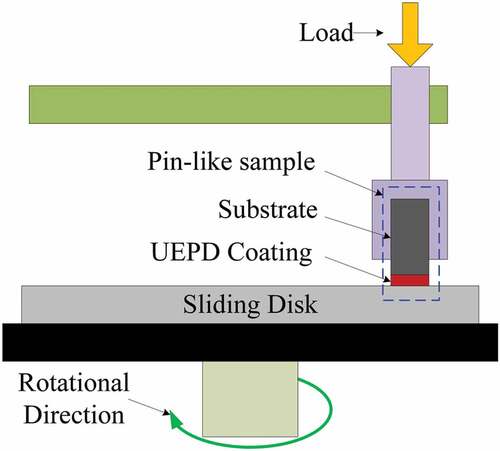
The stationary pins, ϕ 4 × 10 mm, were made from the composite coating and substrate. A sliding disk of ϕ 50 mm, quenched steel (i.e. M390 steel with a hardness of HRC 65), served as the counterbody. The testing was conducted at room temperature. The testing parameters included a constant load of 150 N, a sliding speed of 200 r/min, a friction radius of 15 mm and a sliding time of 30 min. After friction and wear testing, the wear samples were cleaned ultrasonically in a bath containing acetone and weighed to determine their weight loss. The wear rate V was calculated by the following equation:
where ∆W is the mass difference of the pin sample before and after testing, r is the friction radius, t is the sliding time, n is the sliding speed and N is the load. The wear morphology of the pin samples was examined by SEM to identify the wear mechanisms.
3. Results and discussion
3.1. Microstructure and composition analysis
The cross-sectional morphology of the EPD coating is shown in .
Figure 3. Morphologies of the composite coating: (a) cross-sectional view of the EPD coating; (b) surface view of the EPD coating and its (c) 3D image; (d) cross-sectional view of the UEPD coating; and (e) surface view of the UEPD coating and its (f) 3D image.
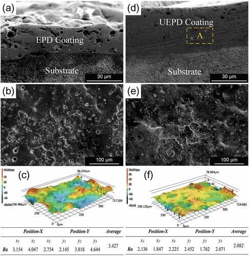
It is observed that an EPD coating with an average thickness of approximately 26.5 μm is formed. However, there are many defects in the coating, such as microcracks and porosities. shows that the EPD coating surface presents a typical sputtering morphology of ESD, and there are also many microcracks and pores. The 3D image shows that the surface topography of the EPD coating exhibits an obvious undulation, and the average roughness is approximately 3.427 μm, as shown in . In contrast, the UEPD coating shows a better preparation quality under the action of ultrasonic assistance. In , it can be observed that few defects are observed inside the UEPD coating, and the compactness and thickness uniformity improve significantly. Moreover, the UEPD coating has an average thickness of approximately 45.5 μm and shows a good bonding state with the substrate. Similarly, a sputtering morphology also appears on the UEPD coating surface, but the microcracks and pores are significantly reduced compared with that of the EPD coating, as shown in . The 3D topography image of shows that the UEPD coating becomes smooth, and the surface roughness decreases to 2.082 μm, which is approximately 39% lower than that of the EPD coating.
The microstructure in the cross-sectional view of the UEPD coating on the cross-profile view is shown in .
Figure 4. Microstructure of the UEPD coating: (a) cross-sectional view of the coating and (b) magnified BSE image for the marked region B; (c) BSE image showing the bright particles and the EDS for the marked particles.
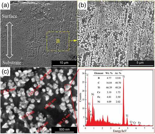
The microstructure in the coating exhibits submicron dendrites. These dendrites grow along the vertical direction of the substrate surface. The formation of submicron grains is mainly attributed to the rapid solidification process of the coating. The morphologic evolution of grains mainly depends on the solute diffusion ability and solidification rate. In the ESD process, the molten pool that forms the coating has an ultrahigh temperature gradient (107–109 K/m) and cooling rate (105–106 K/s), which greatly inhibits the growth of gains [Citation21]. This is also the main reason why the ESD process can produce coatings with special crystal structures, such as nanocrystalline and amorphous coatings [Citation22,Citation23]. In the high magnification BSE image, it is evident that many finer bright particles are distributed in the coating, as shown in . The particles are approximately 100 nm in size and exhibit a distinguishing contrast to the substrate, as shown in . The EDS results show that these particles contain large amounts of Ti (66.39 wt.%) and C (16.84 wt.%), and the atomic percentage of Ti to C is close to 1:1. Therefore, it can be inferred that these particles should be in-situ TiC.
The micrograph of the bonding zone between the UEPD coating and substrate is shown in .
Figure 5. (a) Micrograph of the bonding zone between the UEPD coating and substrate and its (b-c) element distribution.
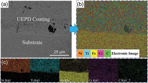
A metallurgical bonding can be observed between the UEPD coating and substrate. The element mapping reveals the element distribution in this zone, as shown in . There is a clear difference in the chemical elements between the UEPD coating and substrate. shows that the chemical elements in the coating area are dominated by Ni and Ti elements and accompanied by a certain amount of Fe, Cr and C elements. In contrast, in the substrate area, Fe is the main component as well as C and Cr elements, but Ti and Ni are almost non-existent.
A careful examination on the middle and bottom regions of UEPD coating (as the A region in ) showed that a few tiny bright granules with different sizes unevenly distribute in the coating, as shown in .
Figure 6. (a) BSE image denoted as A region in and 3b the EDS for the marked granules.
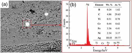
The EDS results (as shown in ) show that the main composition of these granules is Ag (88.05 wt.%). The Ag element is mainly from the Ag powder contained in the conductive adhesive, which is deposited on the substrate together with the composite powder. It is well known that the Ag-Ni is an immiscible alloy system [Citation24]. During the coating formation process, the liquid phase separation occurred in the molten pool of Ag-Ni system due to the rapid cooling, thus led to the Ag granules with different sizes forming in the coating. The presence of these Ag granules maybe has a positive effect on the tribological properties of the coating to a certain extent [Citation25].
The XRD patterns of the H13 steel substrate, composite powder and UEPD coating are shown in .
Figure 7. XRD pattern of the substrate, composite powder and UEPD coating.
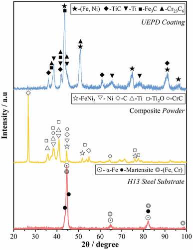
It was observed that the substrate was mainly composed of α-Fe, martensite and (Fe, Cr) solid solutions. As mentioned in section 2.1, the main components of composite powder include FeNi3, Ni, C, Ti, TiO2 and CrC. Among them, FeNi3, Ni and CrC are mainly from Ni-based alloying powder, while C, Ti and TiO2 are mainly from (Ti + graphite) powder. After UEPD processing, the phase components of UEPD coating change greatly compared with those of composite powder and substrate. It mainly includes γ-(Fe, Ni), TiC, Ti, Fe3C and Cr23C6. The appearance of TiC indicates that the in-situ synthesis reaction occurs in the coating, which also confirms the results of the previous microstructure analysis. These in-situ TiCs dispersed in the coating matrix can significantly enhance the physical and mechanical properties of the coating. In addition, the diffraction peaks of Ag or its alloys are not found in the XRD pattern. It may be attributed to the fact that the Ag granules are few in number and uneven distribution and located at the middle and bottom region of coating.
3.2. Formation mechanism of UEPD coating
Based on observations of cross-sectional, surface and bonding interface, it is clear that the formation of the composite coating occurs as a result of the composite powder transfer and attachment from the electrode surface to the substrate surface. The material transfer mechanism of ESD process has been described in several studies [Citation26–29]. According to the difference in the mode of interaction between electrode and substrate, the ESD process can be roughly divided into two categories: contact and non-contact. The contact process is the most popular method at present. Its material transfer depends on the spark discharge generated by the anode electrode and cathode substrate at the moment of contact, which lead to the materials of electrode tip transferring to the substrate via solid, liquid, or gaseous states [Citation27]。In contrast, the non-contact process is more inclined to the gap discharge process of traditional electrical discharge machining (EDM) [Citation28]. The material transfer mainly uses the high temperature generated by spark-discharge of the interelectrode gap to melt and sputter the materials of electrode tip onto the substrate surface. In the UEPD process, the adhesive powder layer as discharge and deposition material has a high surface flexibility, which is difficult to cause local resistance thermal effect like a block electrode. Therefore, the material transfer mechanism of UEPD process is closer to non-contact process. shows the material transfer process of powder layer in dynamic mode within one discharge pulse cycle.
Figure 8. Schematic of transfer process of powder layer in one discharge cycle in the UEPD process: (a) Stage 1; (b-c) Stage 2; (d) Stage 3.
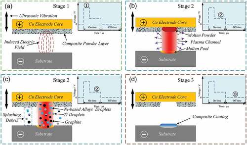
The ideal voltage waveform of gap discharge in traditional EDM is shown in the schematic embedded in [Citation26]. The transfer process can also be divided into three stages. In the stage 1, there is a gap between the powder layer and the substrate surface, and no direct physical contact. The voltage stayed at the preset level of floating voltage, and only the induced electric field exists, as shown in . Under the action of the induced electric field, the insulation medium (air) between poles is broken down, and a local plasma channel forms, i.e. generating electric sparks. The formation of local plasma channel causes a sharp drop in voltage, and the process enters stage 2, as shown in . The plasma channel can generate a high temperature of about 8000–12,000°C while also inducing a localized pressure on the scale of ~200 atm [Citation26]. In the local plasma channel region, the high temperature rapidly heats and melts the powder layer and the substrate surface, resulting in the formation of the molten pool on the substrate surface. Driven by active forces (electromagnetic, electrostatic, shock wave and gravity [Citation30]), the most of components of powder layer, such as Ni-base alloys, Ti and graphite, are ejected and transferred to the surface of substrate in the form of droplets, as shown in . The transferred droplets deposit on the substrate surface, and mix and react with the molten pool, which is the crucial factor to produce metallurgical bonding. In addition, there is a small number of components to be ejected into the surroundings to form splashing debris. When the pulse discharge finishes, the circuit is in an intermittent state, the voltage between the poles returns to zero, and the plasma channel is eliminated. The transfer process enters stage 3, as shown in d.
Figure 9. Microhardness profile of the in-situ TiC-Ni composite coating.
In this stage, due to the termination of heat input, the mixed molten pool on the surface of substrate cools and solidifies rapidly to form a composite coating under the air self-cooling of substrate.
The morphology analysis demonstrates that ultrasonic vibration can play a very positive role in the improvement of forming quality of coatings. During the cooling process, due to the difference in the thermal expansivity between the coating and substrate, an inner stress can be produced in the coating, which causes microcracks in some areas [Citation31]. In addition, the droplets in the atmosphere easily trap and dissolve the gas molecules during the transfer process, and the metallurgical reactions in the molten pool can produce some gases [Citation31,Citation32]. Since these gases cannot be sufficiently released through rapid solidification, pores formed in the coating. The introduction of ultrasonic vibration can change the discharge condition in the process of ESD, which can cause the droplets to break and disperse [Citation33]. The size of the droplet is usually positively correlated with the number of pores, which may be attributed to the fact that large droplets more easily trap gases [Citation7]. Dispersed droplets with smaller sizes can reduce the entrapment of gases during sputtering and reduce the porosity of the coating. In addition, the accumulation of droplets with smaller sizes is more beneficial to the release of thermal stress inside the coating, thus inhibiting the generation of microcracks. It should be noted that the UEPD coating is significantly thicker than EPD coating and exhibits better compactness and lower roughness. It can be also attributed to the positive role of the ultrasonic vibration. The ultrasonic vibration with a high frequency can increase the initial momentum and sputtering speed of the droplets in the sputtering process, which can promote improved spreading of the droplets on the substrate surface. Therefore, the compactness and uniformity of the coating were further improved, as well as surface roughness. Moreover, the higher sputtering speed can also enhance the adhesion of droplets. It may be responsible for the increased thickness of UEPD coating. A combination of the above factors facilitated the UEPD coatings to be of better quality than EPD coatings.
3.3. Synthesis process of in-situ carbides
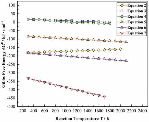
The formation process of coating is also the process that internal components react with each other to form new compounds. XRD results illustrate that the in-situ ceramic phases in the UEPD coating are mainly carbides, including TiC, Fe3C and Cr23C6. During the formation process of coating, the composite powder layer absorbed the energy of electrical discharge to be rapidly melted and then deposited and formed a mixed molten pool on the surface of the substrate. In the mixed molten pool of high temperature, most components of the coating are in a liquid state. The possible metallurgical reactions that may synthesize in-situ carbides are as follows:
The standard Gibbs free energy ΔG0 of these reactions is calculated according to former literature, as shown in . The above equations are combined, and the Gibbs free energy via reaction temperature T was calculated and plotted in .
Figure 10. Diagram of the Gibbs free energy ΔG0 via the reaction temperature T.
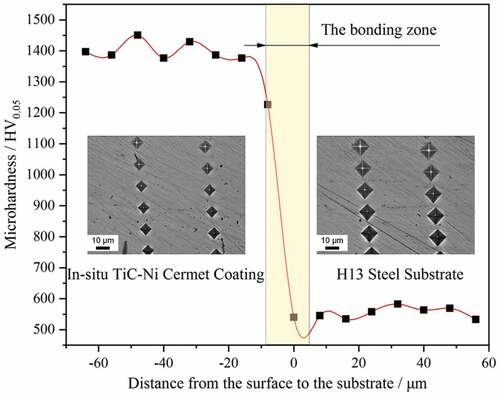
Table 2. Gibbs free energy of reactions as a function of temperature [Citation34–36].
In addition to EquationEquation 3(3)
(3) and EquationEquation 4
(4)
(4) ,
of all other reactions are negative in the range of 298 ~ 2000 K, which indicates that these reactions can spontaneously occur in thermodynamics. It is well known that the driving force of metallurgical reactions is significantly affected by
. A lower
represents a stronger driving force and vice versa. Therefore, the possibility of these reactions follows the order of (7)>(6)>(2)>(5)>(4)>(3).
The microstructure evolution process also needs to consider dynamic factors, such as the concentration and activity of solute atoms [Citation36]. Since the melting point of TiC (~ 3160°C) is significantly higher than that of Cr7C3 (1780°C) and Cr23C6 (1520°C) and the composite powder is rich in Ti, the in-situ TiC can preferentially precipitate from the molten pool [Citation37]. Q. Ma et al. [Citation36] also found that the addition of Ti can suppress the formation of Cr23C6 in the in-situ synthesis process, even though the Cr23C6 has a lower . With the precipitation of TiC particles, many free C atoms were consumed in the molten pool. Due to the few remaining free C atoms, the thermodynamic and dynamic conditions are difficult to satisfy for the formation of carbon-rich carbides Cr3C2 and Cr7C3. Therefore, the Cr and C elements in the molten pool are prone to form the carbon-deficient carbide Cr23C6. In addition, for the Fe-rich carbides, both of Fe3C and Fe2C are metastable phases thermodynamically, so their formation and retention need to provide additional dynamic conditions. It should be emphasized that the concentration of the Fe element in the molten pool is actually higher than that calculated according to the original composite powder, which is due to the mass introduction of the Fe element from the substrate. In the case that strong carbide-forming elements such as Ti and Cr are consumed, a sufficient concentration of Fe leads to a tendency to react with residual C. The formation of Fe3C has a stronger driving force than that of Fe2C due to the lower quantity of
. In addition, the molten pool has a very fast solidification rate and exhibits substantial supercooling, which provides dynamic conditions for the formation and maintenance of metastable Fe3C.
3.4. Hardness & tribological properties characterization
The microhardness profile of the in-situ TiC-Ni composite coating is shown in . In the coating area, the average microhardness was approximately 1400.5 HV0.05, which was approximately 2.5 times that of the substrate (~553.2 HV0.05). The improvement in hardness in the coating may be mainly attributed to two reasons: on the one hand, the formation of submicron grains caused by rapid solidification plays a role in fine-grain strengthening; on the other hand, the reinforcements, such as in-situ TiC, provide dispersion strengthening.
The calculated wear rates of the in-situ TiC-Ni composite coating and substrate under the same conditions are shown in .
Figure 11. (a) Calculated wear rates and (b) friction coefficients of the in-situ TiC-Ni composite coating and substrate.
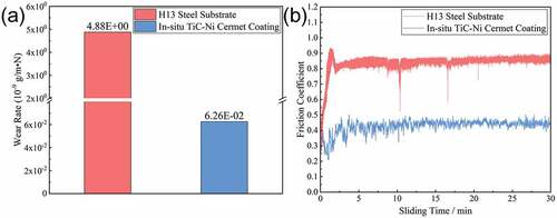
The wear rate of the in-situ TiC-Ni composite coating is approximately 6.26 × 10⁻¹¹ g/m·N, which is approximately 2 orders of magnitude lower than that of the substrate (~4.88 × 10⁻⁹ g/m·N). This indicates that the in-situ TiC-Ni composite coating can significantly improve the wear resistance of the substrate. The FCs of the in-situ TiC-Ni composite coating and substrate plotted against the sliding time are shown in . Both the substrate and coating exhibit a stable sliding process. After the fluctuation in the running-in stage, the FC of the substrate is basically stable at approximately 0.813. In contrast, the running-in stage of the in-situ TiC-Ni composite coating is slightly longer than that of the substrate. This may be related to the higher roughness and hardness of the coating surface. However, the coating exhibits an antifriction capability in a certain extent. The average FC of the coating is only 0.437, which is approximately 46.2% lower than that of the substrate.
3.5. Tribological mechanism analysis
shows the wear morphologies of the substrate and in-situ TiC-Ni composite coating.
Figure 12. Wear morphologies: (a) SE images of the substrate and (b) the magnified BSE image for the marked region C; (c) SE image of the in-situ TiC-Ni composite coating and (d) the magnified BSE image for the marked region D.
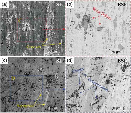
The worn surface of the substrate is relatively rough, and there are some deep and continuous plowing grooves, as shown in . In addition, there are some wear debris layers covering the worn surface. These wear debris layers are mainly composed of oxides, which exhibit a different contrast to the substrate in the BSE mode, as shown in . Thus, it can be concluded that the wear mechanism of the substrate is abrasive wear. In contrast, the in-situ TiC-Ni composite coating exhibits a smoother worn surface, and the wear feature is mainly shallow with discontinuous scratches, as shown in . It should be noted that there are some cracks on the worn surface and some delamination around the cracks, as shown in . The delamination may be related to the surface defects of the coating. In the wear process, mechanical fatigue occurred on the surface material of the coating due to the continuous cyclic load from the counterbody, which resulted in the crack tendency of the surface material. In addition, as the natural crack sources, the original defects in the coating, including the pores and microcracks, not only worsened the fatigue crack tendency but also accelerated the crack growth. Under the action of friction force, the fatigue cracks propagated along the parallel direction of the surface. When these cracks expand to a certain extent and connect with each other, the surface material peels off from the coating, finally causing delamination. The spalling debris can act as abrasive particles, thereby resulting in the formation of scratches on the worn surface [Citation38]. Therefore, it can be concluded that the wear mechanism of the in-situ TiC-Ni composite coating is mainly fatigue wear and abrasive wear.
It can be concluded that the in-situ TiC-Ni composite coating has better tribological properties than the substrate. A higher hardness prompts the in-situ TiC-Ni composite coating to better resist the cutting action of the counterbody, which can enhance the wear resistance. In terms of the antifriction capability, the composite coating also performs better due to its special properties. In general, the friction force mainly comes from adhesion and cutting actions [Citation39]. The substrate of H13 steel is relatively soft, which easily produces cutting behavior with the counterbody in the sliding process. In contrast, the higher hardness of the composite coating can inhibit the cutting action of the counterbody. In addition, the H13 steel has a closer chemical composition to that of the counterbody (M390 steel). In the friction process, the materials of the counterparts with similar chemical compositions have a stronger tendency to adhere and exhibit cold welding, which can also increase the friction force to a certain extent. The composite coating has a large difference in chemical composition from the counterbody, which can reduce the occurrence of cold welding or adhesion during the friction process. Therefore, the FC of the in-situ TiC-Ni composite coating is significantly lower than that of the substrate.
4. Conclusion
In this study, in-situ TiC-Ni composite coatings were successfully prepared on H13 steel by the UEPD process. The morphology, microstructure, microhardness and tribological properties of the composite coatings were investigated in detail. The conclusions obtained from a detailed investigation are as follows:
The composite coating exhibits a sputtering morphology with a surface roughness of approximately 2.082 μm, which also has an average thickness of approximately 45.5 μm and metallurgically bonds with the substrate. The microstructure in the coating is submicron dendrites, and the phase composition included γ-(Ni, Fe), TiC, Cr23C6 and Fe3C as well as residual Ti. In addition, a small number of Ag granules with different sizes is also found in the middle and bottom regions of coatings, which mainly originated from the Ag powder contained in the conductive adhesive.
Under the action of spark discharge, the powder layer adhered on the electrode is rapidly melted and ejected onto the substrate in the form of molten droplets. These droplets mix and react with the molten pool of substrate surface, and then rapidly solidified to form the composite coating. In this process, the TiC particles are synthesized by in-situ reaction of Ti powder with graphite, likewise other in-situ carbides such as Cr23C6 and Fe3C. These in-situ carbides demonstrate the feasibility of in-situ synthesis of composite coatings by using the UEPD process. Moreover, the introduction of ultrasonic vibration can increase the dispersion, initial momentum and sputtering speed of the droplets, which result in better compactness and lower roughness of the coating as well as few defects.
The presence of fine grains and in-situ carbides effectively enhances the hardness and tribological properties of the UEPD coating. The average hardness of the composite coating reaches 1400.5 HV0.05, which is approximately 2.5 times that of the substrate. The wear rate of the composite coating decreases by two orders of magnitude compared with the substrate, and the wear mechanism is mainly fatigue wear and abrasive wear. Additionally, the FC of the coating is also lower than that of the substrate by approximately 46.2%. High hardness and special chemical composition are the main reasons for the high wear resistance and low friction of the in-situ composite coating.
Acknowledgments
This work was supported by National Natural Science Foundation of China (Grant No. 52005342 and 51975385).
Disclosure statement
No potential conflict of interest was reported by the authors.
Additional information
Funding
References
- Kiryukhantsev-Korneev P, Sytchenko A, Sheveyko A, et al. Two-layer nanocomposite TiC-based coatings produced by a combination of pulsed cathodic arc evaporation and vacuum electro-spark alloying. Materials. 2020;13(3):15.
- Jiao Z, Peterkin S, Felix L, et al. Surface modification of 304 stainless steel by electro-spark deposition. J Mater Eng Perform. 2018;27(9):4799–4809.
- Leo P, Renna G, Casalino G. Study of the direct metal deposition of AA2024 by ElectroSpark for coating and reparation scopes. Appl Sci Basel. 2017;7(9):16.
- Renna G, Leo P, Casalino G, et al. Repairing 2024 aluminum alloy via electrospark deposition process: a feasibility study. Adv Mater Sci Eng. 2018;20181. doi:10.1155/2018/8563054
- Wei X, Chen Z, Zhong J, et al. Feasibility of preparing Mo2FeB2 -based cermet coating by electrospark deposition on high speed steel. Surf Coat Tech. 2016;296:58–64.
- Qiao L, Wu Y, Hong S, et al. Wet abrasive wear behavior of WC-based cermet coatings prepared by HVOF spraying. Ceram Int. 2021;47(2):1829–1836.
- Salmaliyan M, Malek Ghaeni F, Ebrahimnia M. Effect of electro spark deposition process parameters on WC-Co coating on H13 steel. Surf Coat Tech. 2017;321:81–89.
- Wang XH, Liu SS, Zhao GL, et al. In-situ formation ceramic particles reinforced Fe-based composite coatings produced by ultrasonic assisted laser melting deposition processing. Opt Laser Technol. 2021;136:106746.
- Straumal BB, Konyashin I, Ries B, et al. Pseudopartial wetting of WC/WC grain boundaries in cemented carbides. Mater Lett. 2015;147:105–108.
- Yang L, Li Z, Zhang Y, et al. Al-TiC in situ composite coating fabricated by low power pulsed laser cladding on AZ91D magnesium alloy. Appl Surf Sci. 2018;435:1187–1198.
- Ma QS, Dong ZX, Ren NN, et al. Microstructure and mechanical properties of multiple in-situ-phases-reinforced nickel composite coatings deposited by wide-band laser. Coatings. 2021;11(1):13.
- Zhao H, J-j L, Zheng Z-Z, et al. Microstructure and high-temperature wear properties of in situ TiC composite coatings by plasma transferred arc surface alloying on gray cast iron. Int J Min Met Mater. 2015;22(12):1273–1282.
- Tkachivskyi D, Juhani K, Surzenkov A, et al. HVOF sprayed Fe-based wear-resistant coatings with carbide reinforcement, synthesized in situ and by mechanically activated synthesis. Coatings. 2020;10(11):15.
- Zhang LZ, Zhao ZY, Bai PK, et al. In-situ synthesis of TiC/graphene/Ti6Al4V composite coating by laser cladding. Mater Lett. 2020;270:127711.
- Frangini S, Masci A. A study on the effect of a dynamic contact force control for improving electrospark coating properties. Surf Coat Tech. 2010;204(16–17):2613–2623.
- Enrique PD, Jiao Z, Zhou NY, et al. Effect of microstructure on tensile properties of electrospark deposition repaired Ni-superalloy. Mat Sci Eng A Struct. 2018;729:268–275.
- Loginov PA, Levashov EA, Potanin AY, et al. Sintered Ti–Ti 3 P–CaO electrodes and their application for pulsed electrospark treatment of titanium. Ceram Int. 2016;42(6):7043–7053.
- Kudryashov AE, Lebedev DN, Potanin AY, et al. Structure and properties of coatings produced by pulsed electrospark deposition on nickel alloy using Mo-Si-B electrodes. Surf Coat Tech. 2018;335:104–117.
- Burkov AA, Pyachin SA. Investigation of WC-Co electrospark coatings with various carbon contents. J Mater Eng Perform. 2014;23(6):2034–2042.
- Yuan YL, Wu HH, You M, et al. Improving wear resistance and friction stability of FeNi matrix coating by in-situ multi-carbide WC-TiC via PTA metallurgical reaction. Surf Coat Tech. 2019;378:124957.
- Wang D, Wang W, Wang M, et al. Effect of operating voltage on microstructure and microhardness of NiCoCrAlYTa-Y2O3 composite coatings on single crystal superalloy produced by electrospark deposition. Surf Coat Tech. 2019;358:628–636.
- Wei X, Chen Z, Zhong J, et al. Facile preparation of nanocrystalline Fe2B coating by direct electro-spark deposition of coarse-grained Fe2B electrode material. J Alloy Compd. 2017;717:31–40.
- Hong X, Tan Y, Zhou C, et al. Microstructure and tribological properties of Zr-based amorphous-nanocrystalline coatings deposited on the surface of titanium alloys by Electrospark Deposition. Appl Surf Sci. 2015;356:1244–1251.
- Rajkumar VB, Chen S-W. Thermodynamic modeling of Ag-Ni system combining experiments and molecular dynamic simulation. J Electron Mater. 2017;46(4):2282–2289.
- Dhandapani VS, Thangavel E, Arumugam M, et al. Effect of Ag content on the microstructure, tribological and corrosion properties of amorphous carbon coatings on 316L SS. Surf Coat Tech. 2014;240:128–136.
- Algodi SJ, Murray JW, Fay MW, et al. Electrical discharge coating of nanostructured TiC-Fe cermets on 304 stainless steel. Surf Coat Tech. 2016;307:639–649.
- Wang X-R, Wang Z-Q, Lin T-S, et al. Mass transfer trends of AlCoCrFeNi high-entropy alloy coatings on TC11 substrate via electrospark − computer numerical control deposition. J Mater Process Tech. 2017;241:93–102.
- Ahmed N, Murray JW, Yuzawa T, et al. Formation of thick electrical discharge coatings. J Mater Process Tech. 2020;285:116801.
- Liu Y, Wang D, Deng C, et al. Feasibility study on preparation of coatings on Ti–6Al–4V by combined ultrasonic impact treatment and electrospark deposition. Mater Design. 2014;634:88–92.
- Ribalko AV, Korkmaz K, Sahin O. Intensification of the anodic erosion in electrospark alloying by the employment of pulse group. Surf Coat Tech. 2008;202(15):3591–3599.
- Farahmand P, Liu S, Zhang Z, et al. Laser cladding assisted by induction heating of Ni–WC composite enhanced by nano-WC and La2O3. Ceram Int. 2014;40(10):15421–15438.
- Zhou S, Zeng X, Hu Q, et al. Analysis of crack behavior for Ni-based WC composite coatings by laser cladding and crack-free realization. Appl Surf Sci. 2008;255(5):1646–1653.
- Chigrinova NM, Lovygin SI, Chigrinov VE. Role of ultrasound in mechanisms of anode-cathode interactions during electrospark alloying. Sci Tech. 2016;15(5):380–390.
- Wu Q, Li W, Zhong N, et al. Microstructure and wear behavior of laser cladding VC–Cr7C3 ceramic coating on steel substrate. Mater Design. 2013;49:10–18.
- Wang XH, Zou ZD, Qu SY, et al. Microstructure and properties of the TiC/Fe-based alloy hardfacing layers. J Mater Sci. 2005;40(14):3629–3633.
- Ma Q, Li Y, Wang J. Effects of Ti addition on microstructure homogenization and wear resistance of wide-band laser clad Ni60/WC composite coatings. Int J Refract Met H. 2017;64:225–233
- Huang SM, Sun DQ, Wang WQ, et al. Microstructures and properties of in-situ TiC particles reinforced Ni-based composite coatings prepared by plasma spray welding. Ceram Int. 2015;41(9):12202–12210.
- Chen GQ, Fu XS, Wei YH, et al. Microstructure and wear properties of nickel-based surfacing deposited by plasma transferred arc welding. Surf Coat Tech. 2013;228:S276–S282.
- Zhao H, Li J, Zheng Z, et al. The microstructures and tribological properties of composite coatings formed via PTA surface alloying of copper on nodular cast iron. Surf Coat Tech. 2016;286:303–312.