
 ?Mathematical formulae have been encoded as MathML and are displayed in this HTML version using MathJax in order to improve their display. Uncheck the box to turn MathJax off. This feature requires Javascript. Click on a formula to zoom.
ABSTRACT
In this study, lead-free 0.8(Bi,Na)TiO3-0.2(Sr,Ti)O3 piezoelectric ceramics were prepared using a two-step sintering process to analyze their sintering mechanisms. Two-step sintering process has benefits of being able to be conducted at lower temperatures than conventional sintering process, but the complicated sintering mechanisms involved in this process have not been yet fully investigated. Therefore, in the present study, two-step sintering mechanism for lead-free piezoelectric ceramics was analyzed by estimating the activation energy required depending on the sintering conditions. Using the two-step sintering process, the piezoelectric charge and electromechanical coupling coefficients improved from 146 pC/N and 0.347 to 163 pC/N and 0.377, respectively. By comparing the grain-growth mechanisms for the conventional and two-step sintering processes, it appeared that the sintering mechanisms differed. By introducing the two-step sintering process, piezoelectric ceramics with improved piezoelectric charge and electromechanical coupling coefficients were produced.
1. Introduction
Lead-based piezoelectric ceramics have advantages of higher piezoelectric properties compared with those of lead free piezoelectric ceramics. The sintering temperature of PZT or PMN-PT ceramics is around 1200°C with excellent piezoelectric properties which is a relatively lower sintering temperature compared with that of lead-free BZT-BCT ceramics which is around 1500°C Also, lead-free piezoelectric ceramics have advantages of environmental aspects unlike lead-based ceramics [Citation1,Citation2]. However, they have lower piezoelectric properties as well as higher sintering temperatures [Citation3]. High sintering temperatures induce volatilization problems and complicate processing. Therefore, to lower the sintering temperature, many attempts have been made including two-step sintering process. Generally, ceramics fabricated by two-step sintering process have a lower temperature than conventional sintering process. Still, due to the long sintering time in the second step sintering process, grains can grow with uniform grain size, and pores are reduced by large margin, resulting in dense ceramics. The two-step sintering process is divided into two stages: coarsening and densification [Citation4]. The two-step sintering process produces ceramics with a uniform grain size and high density compared with the existing process in which coarsening and densification co-occur. Another advantage of the two-step sintering process is that elemental losses can be avoided because sintering is performed at a relatively low temperature [Citation5,Citation6]. For example, alkali niobate-based ceramics prepared by two-step sintering have been reported to have a piezoelectric charge coefficient of 510 pC/N, resulting in improved piezoelectric properties compared with ceramics made with conventional processes (~250 pC/N) [Citation7,Citation8]. In addition, it is reported that barium titanate produced by the two-step sintering process showed a higher piezoelectric charge coefficient of 460 pC/N than the ceramic produced by the conventional sintering process (200 pC/N) [Citation9,Citation10].
Bi0.5Na0.5TiO3 (BNT)-based ceramics is another lead-free piezoelectric material that has a relatively moderate d33 (~180 pC/N), a high Tc (~300°C), and a large residual polarization of 38 pC/cm2 [Citation11–13]. However, its high conductivity makes the polarization process difficult. Doping has been suggested as a solution to increase the resistivity of piezoelectric ceramics. In particular, SrTiO3 was added to BNT ceramics in this study to increase their resistivity since SrTiO3 is an incipient paraelectric material with high resistivity. Volatile Na and Bi components can easily evaporate during the sintering process, leaving vacancies in the BNT ceramic structure. These vacancies induce leakage current [Citation14,Citation15]. To increase densities and resistivity in the piezoelectric ceramics, high pressure was applied to the specimens.
In general, hot pressing, quenching, or two-step sintering processes are preferably used to prepare dense ceramics for such volatile materials [Citation7,Citation16,Citation17]. Among these processes, two-step sintering is known to prevent element loss since it involves a long-term second sintering process that requires a lower temperature than conventional sintering processes [Citation6,Citation18]. In addition, two-step sintering can improve the piezoelectric properties by improving the microstructure, grain size, and homogeneity of the specimen. Nevertheless, studies on the mechanism and required energy for the two-step sintering process of BNT-ST ceramics have not been yet performed by employing numerical model between sintering temperature and grain size. In this study, a two-step sintering mechanism of lead-free piezoelectric ceramics of BNT-ST was investigated. Previously, studies on the two-step sintering of BNT-ST ceramics have been reported [Citation19]. The sintering energy was calculated from the BNT20ST composition, and the sintering mechanism was analyzed in depth through the grain growth kinetic exponent for the first time. Thus, the sintering mechanism for two-step sintering process was studied to analyze the grain-growth process by considering the sintering temperature and holding time in order to predict and control the piezoelectric properties.
2. Experimental procedure
In this study, 0.8(Ba0.5Na0.5)TiO3–0.2SrTiO3 (BNT–ST) powder was prepared through a traditional oxide solid-phase reaction using Bi2O3 (purity 99.9%, Sigma-Aldrich Co., Ltd., Germany), Na2CO3 (purity 99.0%, Sigma-Aldrich Co., Ltd., Germany), TiO2 (purity 99.9%, Kojundo Chemical Lab. Co., Ltd., Japan), and SrCO3 (purity 99.9%, Sigma-Aldrich Co., Ltd., Italy). First, the stoichiometrically weighed powder was ball milled with ethanol and yttria-stabilized zirconia ball for 24 h. Thereafter, the obtained slurry was dried in an oven and calcined at 850°C for 2 h. After the calcination process, the dried slurry was filtered through a 100-μm mesh to obtain a powder. For ease of molding, PVA (Polyvinyl Alcohol) was used as a binder in an amount of 5 wt%. Uniaxial pressure molding was performed at about 200 MPa to produce the specimens as disks with a diameter of 12 mm. Uniaxial pressure molding was performed at about 200 MPa to produce the specimens as disks with a diameter of 12 mm.
To prepare the sample using the conventional sintering process, the temperature was raised to 5°C/min and maintained at 600°C for 1 h to remove the binder. Thereafter, the sample was sintered at elevated temperatures of 1125°C, 1150°C, 1175°C, 1200°C, and 1225°C for 2 h.
The two-step sintering process involved a pre-sintering step and a secondary sintering step at an adjusted temperature. The pre-sintering temperature for the two-step sintering process was selected by considering the sintering time and temperature of the conventional sintering process. The secondary-step sintering temperature was set to be 100°C lower than the pre-sintering temperature (cooldown rate, 50°C/min). The secondary-step sintering time for the two-step sintering process was adjusted to 0, 6, 12, 18, 24, 30, and 36 h. The prepared ceramics were coated with silver paste on both surfaces and fired at 700°C for 10 min. The polling process was performed in a silicone oil bath at room temperature for 30 min using a DC electric field of 4 kV/mm.
Field-emission scanning electron microscopy (FE-SEM; Carl Zeiss, SIGMA 300) was performed to study the grain size. Pt ion was coated on the unpolished sample after washing ethanol to analyze FE-SEM. We measured about 120–140 grains in the conventional sintering process sample and about 230–260 grains in the two-step sintering process sample. The grain size was measured by the Feret diameter method [Citation20]. Average grain size was calculated as the geometric mean of the short and long edges for rectangular-shaped grains. If it was difficult to determine the grain’s longest and shortest edge, the grain size was measured at an angle of about every 30° and averaged. The density of the BNT–ST ceramics was measured using the Archimedes method. The value of d33 was measured using a Berlincourt-type d33 meter (YE2730A d33 meter). The electromechanical coupling coefficient (kp) was calculated and estimated using the following formula [Citation21–23]:
where fa and fr are the antiresonant and resonant frequencies measured with an impedance analyzer (Agilent 4294A), respectively.
3. Results and discussion
To determine the optimum two-step sintering temperature, the BNT–ST ceramics were sintered at 1125°C, 1150°C, 1175°C, 1200°C, and 1225°C using the conventional sintering process. shows the BNT-ST ceramic fabricated by the conventional sintering process. The grain size increased in the sintering temperature increased from 1125°C to 1175°C. However, the grain size became non-uniform when the sintering temperature was between 1200°C and 1225°C. Numerous pores were observed as the temperature approached 1225°C. In general, it is a reported that the electrical properties were improved in a ceramic having a dense microstructure [Citation24]. As a result, it can be predicted that the electrical properties can be improved near the sintering temperature of 1175°C.
Figure 1. FE-SEM micrographs and distribution of the BNT–ST ceramics after the conventional sintering at sintering temperatures of (a) 1125°C, (b) 1150°C, (c) 1175°C, (d) 1200°C, and (e) 1225°C and (f) FE-SEM micrographs of the BNT–ST powder before the sintering process.
shows the relative density and average grain size of the BNT–ST ceramics sintered at 1125°C–1225°C. The relative density and average grain size of the BNT–ST ceramics increased as the sintering temperature increased from 1125°C to 1175°C. It can be observed that the relative density slightly increased at 1200°C and decreased at 1225°C. As shown in ), the density decreased as the pores increased. The grain size was estimated based on the sintering temperature and sintering time using the following formula [Citation25–27]:
Figure 2. Relative density and average grain size of the BNT–ST ceramics as a function of the sintering temperature after the conventional sintering process.
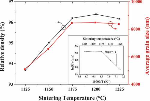
where G and G0 are the average grain sizes after and before the sintering process, n is the grain growth kinetic exponent, t is the sintering time, k0 is the proportional constant based on the sintering mechanism, Q is the activation energy of the grain growth, R is the gas constant, and T is the sintering temperature. As described later, G0c is G0 in the conventional sintering process, and G0t is G0 in the two-step sintering process. If G is considerably larger than G0, then G0 can be omitted as EquationEquation (3)(3)
(3) :
As shown in , since the grain size of ceramics sintered through the conventional sintering process is much larger than G0c, the activation energy can be calculated using EquationEquation (3)(3)
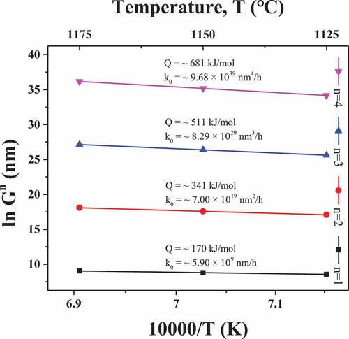
(3) . The only factors that affect the slope of the sintering temperature and average grain size are Q and n. Therefore, the Q of the sintering process can be calculated from the average grain size of the log scale in and the slope (Q/R) of the equation for the reciprocal of temperature. Therefore, Q and k0 were calculated over the sintering temperature range of 1125°C–1175°C for different values of n. The slope was 2 in this range.
shows the calculated Q and k0. At n = 1, 2, 3, and 4, Q was calculated as 681, 511, 341, and 170 kJ/mol, respectively, and k0 was calculated 5.90 × 10⁹ nm/h, 7.00 × 10¹⁹ nm2/h, 8.29 × 1029 nm3/h, and 9.68 × 1039 nm4/h, respectively. It can be seen that Q increases linearly, and k0 increases exponentially according to the value of n. When n was the same in the sintering temperature range of 1125°C–1175°C, Q was also constant. As shown in , the grain growth was completed at 1175°C because the trend changed at 1175°C. Gao et al. confirmed that n was 1.7 and Q was 393.4 kJ/mol when 0.92Bi0.5Na0.5TiO3–0.08BaTiO3 ceramics were made using the conventional sintering process [Citation28]. From Gao’s report and our result in , we can argue that n = 2 and Q = 341 kJ/mol can be the optimized parameters for the sintering conditions in our experiment, since BNT-BT has similar components and structure with those of BNT-ST.
Figure 3. Plots of grain size versus sintering temperature for estimating Q after the conventional sintering process.
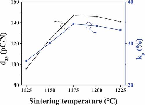
depicts the d33 and kp at the measured sintering temperature. At sintering temperatures of 1125°C, 1150°C, and 1175°C, d33 was 96, 123, and 146 pC/N, respectively, while kp increased to 0.259, 0.301, and 0.348, respectively. However, at sintering temperatures of 1200°C and 1225°C, d33 decreased to 145 and 142 pC/N, respectively, while kp decreased to 0.344 and 0.332, respectively. When the ceramics were sintered at 1175°C, the most uniform and dense microstructure appeared, and the highest piezoelectric properties were obtained. Therefore, the sintering temperature of 1175°C was set as the pre-sintering temperature of the two-step sintering.
Figure 4. Piezoelectric charge coefficient, d33 and electromechanical coupling coefficients, kp of the BNT–ST ceramics after conventional sintering at sintering temperatures of 1125°C, 1150°C, 1175°C, 1200°C, and 1225°C.
To fabricate the BNT–ST ceramics with the two-step sintering process, pre-sintering was performed for 10 min to achieve pre-coarsening at 1175°C, which is the optimum sintering temperature for the existing sintering process. Thereafter, the secondary sintering holding time (t2) was set to 0, 6, 12, 18, 24, 30, and 36 h, and the BNT–ST ceramics were fabricated by performing secondary sintering at 1075°C.
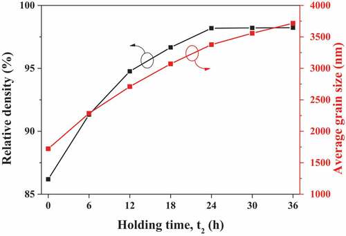
shows the average grain size and relative density of the BNT–ST ceramics as a function of t2. As shown in , relative density was increased up to 98% with increasing holding time t2. When holding time t2 approached 24 h and then relative density was saturated. Also, the average grain size was continuously increased with holing time t2; however, the increasing ratio was decreased after 24 h holding time t2.
Figure 5. Average grain size and relative density of the BNT–ST ceramics as a function of t2 of the secondary sintering process.
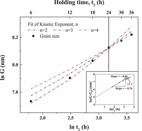
shows the grain size as a function of t2. The plots for estimating in refer to k0 and Q calculated in . As shown in , G0t is small enough to be compared with the grain size after the two-step sintering process, so EquationEquation (2)(2)
(2) was used. The portion indicated by the dotted line represents the theoretical value of the grain size according to n. When t2 was less than 24 h, the exponent n of grain size G was found between 2 and 3. Exponent n is more converged to 2 rather than 3, while n converged to 4 when the sintering time was more than 24 h. From the result of the calculated values of n, we can argue that 24 h of sintering time t2 located in the time boundary for the different sintering mechanism for the two-step sintering process. Inset in explains grains size variation dependent on the holding time with different slope k from EquationEquation (2)
(2)
(2) . As we have discussed before, holding time 24 h has important meaning of boundary time for different sintering mechanisms. As shown in the inset, slope has different values of 0.46 and 0.76. It means that two different sintering mechanisms exist in the BNT-ST two-step sintering process.
Figure 6. Ln G versus t2 plots for estimating the grain growth kinetic exponent (n) after two-step sintering.
shows the FE-SEM image of the BNT–ST ceramics prepared using the two-step sintering process. As shown in the FE-SEM images, as t2 increased up to 24 h, the pores decreased. Therefore, the density was increased as discussed in . However, as hold time t2 increased further than 24 h, the average grain size increased. Therefore, two different sintering mechanisms can exist in the BNT-ST two-step sintering mechanism as we have discussed in . As shown in and (g), the grain size was increased without pore decreasing. This phenomenon can be explained by considering , which displays two-step sintering hold time t2 versus exponent n. As the hold time t2 increases, n changes from 2 to 4, which explains the reason that main grain growth mechanism has changed from decreasing of pore state to grain growth state. According to Brook, sintering mechanisms are largely divided into two categories: pore control and boundary control [Citation29]. After 24 h, the density converged as shown in , and the decrease in pores was not clear as shown in the FE-SEM image of . From this, it can be inferred that pore control mainly occurred, and then the sintering time exceeded 24 h and boundary control became the main mechanism. In the pore control step, n ranges from 2 to 3, and in this process, movement and volatilization of internal pores mainly occur. On the other hand, in the boundary control step, n was confirmed to be 4, and since grain boundary diffusion mainly occurs, it seems that grains of irregular size increased as a result. The simulated values of n and Q based on t2 are listed in .
Table 1. Average grain size, n, and Q values based on the two-step sintering process.
Figure 7. FE-SEM micrographs and grain size distribution of the BNT–ST ceramics after two-step sintering at various t2: (a) 0 h, (b) 6 h, (c) 12 h, (d) 18 h, (e) 24 h, (f) 30 h, and (g) 36 h.
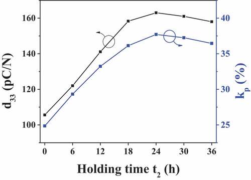
shows the d33 and kp of the BNT–ST ceramics fabricated through two-step sintering. The d33 and kp had maximum values of 163 pC/N and 0.377, respectively, when the sintering time was 24 h. The d33 increased by 10.9%, while the kp increased by 8.6%. This is because the density of the fabricated ceramics was increased by controlling the internal pores of the ceramics through the two-step sintering process. Therefore, it is evident that the two-step sintering process was effective in fabricating high-density ceramics and improving their electrical properties.
Figure 8. Piezoelectric charge coefficient, d33 and electromechanical coupling coefficients, kp of the BNT–ST ceramics after two-step sintering for various t2 of 0 h, 6 h, 12 h, 18 h, 24 h, 30 h, and 36 h.
4. Conclusions
In this study, two-step sintering process was investigated to analyze the sintering mechanism of 0.8(Bi,Na)TiO3-0.2(Sr,Ti)O3 ceramics by considering grain size G and sintering holding time t2. Exponent n for grain size and activation energy Q for the sintering process was simulated by varying the sintering time t2. Two different grain growth mechanisms were observed as varying holding time t2, n = 2–3 for 0–24 h of holding time and n = 4 for 24–36 h of holding time, respectively. By varying the holding time, at first, the porosity was decreased for n = 2–3, and second, the grain size was increased for n = 4. Different sintering mechanism was observed and explained by observing the ceramic porosity and grain size. The lead-free piezoelectric BNT–ST ceramics fabricated by the two-step sintering process under optimized conditions had a d33 and kp of 163 pC/N and 0.377, respectively. By employing the two-step sintering process, the piezoelectric properties were improved around 10%. Therefore, the two-step sintering process is effective in improving the electrical properties of high-density lead-free piezoelectric BNT–ST ceramics.
Acknowledgement
We thank Professor Masaya Ichimura for his assistance during the research.
Disclosure statement
No potential conflict of interest was reported by the authors.
Additional information
Funding
References
- Goodman P, Strudwick P, Skipper R. Technical adaptation under directive 2002/95/EC (RoHS)-investigation of exemptions. ERA Rep. 2004;0603.
- Panda PK. Review: environmental friendly lead-free piezoelectric materials. J Mater Sci. 2009;44(19):5049–5062.
- Jia B, Xi Z, Guo F, et al. Enhanced piezoelectric properties in new ternary ceramics CuO-doped PSN-PMN-PT by low-temperature sintering. Ceram Int. 2021;47(7):9325–9331.
- Kang SJL. Sintering: densification, grain growth, and microstructure. Vol. 4. Oxford: Elsevier Butterworth-Heinemann; 2005. p. 39–56.
- Meng W, Zuo R, Su S, et al. Two-step sintering and electrical properties of sol–gel derived 0.94(Bi0.5Na0.5)TiO3–0.06BaTiO3 lead-free ceramics. J Mater Sci Mater Electron. 2011;22:1841–1847.
- Chen IW, Wang XH. Sintering dense nanocrystalline ceramics without final-stage grain growth. Nature. 2000;404:168–171.
- Hao J, Bai W, Shen B, et al. Improved piezoelectric properties of (KxNa1-x)0.94Li0.06NbO3 lead-free ceramics fabricated by combining two-step sintering. J Alloys Compd. 2012;534:13–19.
- Ishihara S, Kakimoto K, Kagomiya I. Densification of (Na,K)NbO3 piezoelectric ceramics by two-step mixing process. J Mater Sci. 2011;46:3822–3827.
- Hoshina T, Takizawa K, Li J, et al. Domain size effect on dielectric properties of barium titanate ceramics. Jpn J Appl Phys. 2008;47(9):7607–7611.
- Huan Y, Wang X, Fang J, et al. Grain size effects on piezoelectric properties and domain structure of BaTiO3 ceramics prepared by two-step sintering. J Am Ceram Soc. 2013;96:3369–3371.
- Xiao DQ, Lin DM, Zhu JG, et al. Investigation on the design and synthesis of new systems of BNT-based lead-free piezoelectric ceramics. J Electroceram. 2006;16:271–275.
- Song G, Liu F, Zhang F, et al. High-throughput preparation and properties investigation of BNT based lead-free piezoelectric ceramics. IOP Conf Ser Mater Sci. 2019;678:012140.
- Reichmann K, Feteira A, Li M. Bismuth sodium titanate based materials for piezoelectric actuators. Materials. 2015;8:8467–8495.
- Xu L, Wu S, Zhu K, et al. Enhanced piezoelectricity and reduced leakage current of a novel (1 − x)Bi0.5Na0.5TiO3– x(Sr 0.7Bi 0. 2□ 0.1)TiO 3 thin film. Inorg Chem Front. 2021;8:700–771.
- Sakamoto W, Makino N, Lee BY, et al. Influence of volatile element composition and Mn doping on the electrical properties of lead-free piezoelectric (Bi0.5Na0.5)TiO3 thin films. Sens Actuators A. 2013;200:60–67.
- Stenzel A, Fähsing D, Schütze M, et al. Volatilization kinetics of chromium oxide, manganese oxide, and manganese chromium spinel at high temperatures in environments containing water vapor. Mater Corros. 2019;70:1426–1438.
- Lee MH, Kim DJ, Choi HI, et al. Thermal quenching effects on the ferroelectric and piezoelectric properties of BiFeO3−BaTiO3 ceramics. ACS Appl Electron Mater. 2019; 1:1772–1780.
- Meng W, Zuo R, Su S, et al. Two-step sintering and electrical properties of sol–gel derived 0.94(Bi0.5Na0.5)TiO3–0.06BaTiO3 lead-free ceramics. J Mater Sci. 2011;22:1841–1847.
- Liu X, Xue S, Wang F, et al. Grain size dependent physical properties in lead-free multifunctional piezoceramics: a case study of NBT-xST system. Acta Materialia. 2019;164:12–24.
- Arai Y. Chemistry of powder production. London: Springer Science & Business Media; 1996. p. 6.
- Erhart J, Tutu S. Effective electromechanical coupling for the partially electroded ceramic resonators different geometries. The annals of “Dunarea De Jos” university of fascicle IX. Metall Mater Sci. 2015;38:7–16.
- Yamashita Y, Harada K, Hosono Y, et al. Effects of B-site ions on the electromechanical coupling factors of Pb(B’B”)O3–PbTiO3 piezoelectric materials. Jap J Appl Phys. 1998;37:5288.
- Chen F, Kong L, Song W, et al. The electromechanical features of LiNbO3 crystal for potential high temperature piezoelectric applications. J Materiomics. 2019;5:73–80.
- Randall CA, Kim N, Kucera JP, et al. Intrinsic and extrinsic size effects in fine-grained morphotropic-phase-boundary lead zirconate titanate ceramics. J Am Ceram Soc. 1998;81:677.
- Senda T, Bradt RC. Grain growth in sintered ZnO and ZnO-Bi2O3 ceramics. J Am Ceram Soc. 1990;73:106–114.
- Wang X, Zhao J, Cui E, et al. Grain growth kinetics and grain refinement mechanism in Al2O3/WC/TiC/ graphene ceramic composite. J Eur Ceram Soc. 2021;41:1391–1398.
- Roy S, Roy TK, Das D. Grain growth kinetics of Er2O3 doped ZnO-V2O5 based varistor ceramics. Ceram Int. 2019;45:24835–24850.
- Gao F, Hong RZ, Liu JJ, et al. Grain growth kinetics of textured 0.92Na0.5Bi0.5TiO3—0.08BaTiO3 ceramics by tape casting with Bi2.5Na3.5Nb5O18 templates. J Electroceram. 2010;24:145–152.
- Brook RJ. Controlled grain growth. Treatise Mater Sci Technol. 1976;9:331–364.