
 ?Mathematical formulae have been encoded as MathML and are displayed in this HTML version using MathJax in order to improve their display. Uncheck the box to turn MathJax off. This feature requires Javascript. Click on a formula to zoom.
ABSTRACT
In this paper, virtual synchronous generator (VSG) model based control of photovoltaic power generations (PVs) for power system stability improvement is proposed. Different from other studies on VSG, a large-scale power system is the main target of the proposed control. Therefore, digital simulations are conducted using the IEEJ WEST 10-machine System Model, which is a typical large-scale power system model in Japan. In this power system, the system stabilization effect of the control is verified. In addition, the storage capacity of the energy storage device in PV required for achieving the control is evaluated. The simulation results show that the proposed control is more effective for the system stability improvement than the constant power control of the PV. In addition, it is shown that AVR function of the VSG model based control is necessary in the power system with poor voltage stability.
1. Introduction
Recently, a large amount of photovoltaic power generations (PVs) have been installed into power systems, and the ratio of PVs to other synchronous generators (SGs) has increased. There is a concern that when the ratio increases, the total rotational inertia in the whole power systems decreases. SGs can absorb small disturbances and contribute to the system stabilization. On the other hand, PVs cannot because they do not have the rotational inertia. Therefore, even a small disturbance might affect the system stability as the ratio increases. As a countermeasure, virtual synchronous generator (VSG) model based control of PV has so far been proposed [Citation1]. By installing a small capacity of energy storage device in the PV and controlling it, PV can emulate the characteristics of SG with a rotational inertia. Though there are several studies about VSG [Citation2–Citation7], the simulations have been mainly conducted in micro grids. Therefore, it has been unclear that the system stabilization effect of VSG in a large-scale power system. In addition, the capacity of energy storage device in PV has not been evaluated in detail.
In this paper, a new VSG model based control of PV is proposed. Different from other studies on VSG, a large-scale power system with a massive integration of PVs is the main target of the proposed control. The system stabilization effect of the proposed control of PV is verified from digital simulations. As a large-scale power system, the IEEJ WEST 10-machine System Model, which is a typical large-scale power system model in Japan, is used. In addition, the capacity of the energy storage device in PV required for achieving the control is evaluated.
2. VSG model based control
2.1. Structure of PV system with VSG model based control
shows the structure of the PV system with the VSG model based control. A small energy storage device and an inverter is attached to the ordinary PV system. A conventional SG can absorb small disturbances in a power system by changing its rotational energy. However, PV generates electrical power not from mechanical rotational energy. Therefore, in order to make the PV emulate the characteristics of the SG with a rotational inertia,
Figure 1. The structure of VSG model based control.
it is required to equip the PV with an energy storage device. When the input power from the PV panel is higher than the output power, the energy storage device is in charging mode and in the reverse situation, it is in discharging mode. These behaviors enable PVs to emulate the change of the rotational energy of the SG.
The control strategy of each converter/inverter is as follows.
(a) DC/AC inverter connected to the power system
This inverter is controlled in order to make the PV emulate the characteristics of the SG with the
rotational inertia. The output characteristics are explained in Section 2.2 in detail.
(b)DC/DC converter connected to the PV panel
This converter is controlled in order to keep
the output from the PV panel constant. The difference between the output from the PV panel and the output to the power system is compensated by the energy storage device.
(c)DC/DC converter connected to the energy storage device
As described above, this converter is controlled in order to compensate the difference between the output from the PV panel and the output to the power system.
2.2. Proposed VSG model based control method
There are several models of SG in rotor angle stability analysis. In this paper, the model without the damper circuits is adopted in the proposed VSG model based control. shows the d-q axes equivalent circuits of the VSG model [Citation8]. The Equations (1) ~ (16) show the characteristics of the VSG model based control. In the VSG model control, the characteristics of AVR is considered and is simulated as the first order lag transfer function for simplicity.
Figure 2. VSG model equivalent circuit.
Rotational motion
Interlinkage magnetic flux
D-q axis current references
Circuit constants
AVR
: Virtual rotor angle, virtual rotor speed
: Virtual inertia constant, virtual damper coefficient
: D-q axis PV currents
: D-q axis PV current references
: D-q axis voltages of PV-connected point
: Virtual interlinkage magnetic flux, virtual field current
: Virtual field winding resistance
: Virtual internal reactances
: Virtual field voltage
: AVR gain, AVR time constant
shows the VSG model based control diagram. From the equations above, ,
and
are obtained. By imposing the upper and lower limit to
and
, it is possible to prevent the overcurrent from flowing through the DC/AC inverter. shows the constants of the VSG model based control.
Table 1. The constants of the VSG model based control.
Figure 3. VSG model based control diagram.
Moreover, the DC/AC inverter in this paper is the voltage-source inverter. Therefore, the voltage reference must be obtained. As shown in , the d-q axis voltage references (,
) are obtained from
and
.
Figure 4. ACR [Citation9].
![Figure 4. ACR [Citation9].](/cms/asset/cde127d2-c241-4849-993a-585d979903b6/tjee_a_1477094_f0004_b.gif)
In this paper, the outputs of the PV panel and the energy storage device are considered simply. The output from the PV panel is assumed to be constant considering that the amount of solar radiation does not change in the simulation. The output of the energy storage device follows the difference between the output from the PV panel and the output to the power system in the first order lag relationship with time constant being 0.01 second.
3. Power system model
3.1. Subordinate power system model
So far, the time domain simulations with the IEEJ WEST 10-machine system model have been carried out without considering subordinate power system in most of studies. However, it is considered that the existence of the subordinate power system affects the system stabilization. In addition, it is assumed that the effect becomes bigger with a massive integration of PVs.
shows the subordinate power system in the paper [Citation10]. The load and PV are connected at the 100/200V node and the 77kV node. The ratios of the load to the total load are 70% at the 100/200V node and 30% at the 77kV node. The ratios of PV to the total PV are 50% at both the 100/200V and the 77kV. In order to match the power flow of the power system with and without the subordinate power system, some adjustments are needed. Phase modifiers are installed to the 6.6kV sides of the 77kV/6.6kV transformer and the 500kV nodes. Moreover, the voltage designated value, the tap ratio of the 77kV/6.6kV transformer, and the active power consumption of the loads are adjusted.
Figure 5. Subordinate power system [Citation10].
![Figure 5. Subordinate power system [Citation10].](/cms/asset/8733e947-3503-4bf8-8960-a342f23f05c4/tjee_a_1477094_f0005_b.gif)
3.2. Induction motor
Roughly speaking, induction motor (IM) loads have the constant input power characteristics. When the voltage at the connection point of an induction motor load drops due to the system fault, the electrical consumption of the induction motor load also drops. After that, however, it recovers by the increase of the slip of the induction motor, therefore it can be said that induction motor loads approximately show the constant output power characteristic.
The rotor speed and the slip of IM are represented by the Equations (17) and (18).
Rotor speed of induction motor, inertia constant
Input torque, output torque
s: Slip of induction motor
: Synchronous speed of induction motor
: Active and reactive power consumption
: Mechanical output
: Primary resistance, secondary resistance
: Primary reactance, secondary reactance
: Magnetizing reactance
: Terminal voltage
Usually, is proportional to
,
, or
. In this paper,
is proportional to
.
shows the equivalent circuit of IM. From this circuit and the slip, the consumption of IM is obtained.
Figure 6. Equivalent circuit of IM.
4. Simulation
4.1 Simulation conditions
shows the IEEJ WEST 10-machine System Model [Citation11] used in this paper. Node 11 ~ 27 are load nodes, and when the subordinate power systems mentioned in Section 3.1 are considered, they are replaced with respectively. The total outputs of PVs are 30% of the total load consumptions.
Figure 7. IEEJ WEST 10-machine system model.
In this simulation, a three phase ground fault occurs at node 26 side between nodes 25 and 26. The fault occurs at 0.25 seconds, and after 0.07 seconds, the fault is cleared by opening the circuit breaker of the faulted line. After that, the line is reconnected after 7 seconds by closing the circuit breakers.
In this paper, by comparing three cases in the following, the effects of the VSG model based control for the system stability improvement and the same model with AVR equipped are evaluated.
Case 1) PV output constant control
Case 2) VSG model based control
Case 3) VSG model based control (w/o AVR)
In Case 1, the PV output constant control is the control method that aims to keep the output of PV constant. In Case 3, is fixed.
4.2. Simulation 1: without the subordinate power system and induction motor
In this section, the simulation results without the subordinate power system and the induction motor mentioned in the Chapter 3 are shown. shows the internal phase angle differences between G1 and G10. From this figure, it is confirmed that the VSG model based control can suppress the power system fluctuation more rapidly than the PV output constant control. From this result, it can be said that in the large-scale power system, the VSG model based control improves the power system stability.
Figure 8. Internal phase angle differences.
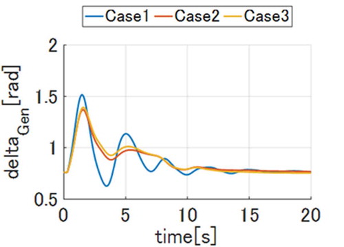
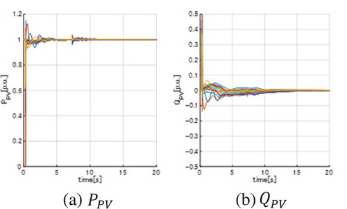
In , the difference between Case 2 and Case 3 is very small. In this power system, the node voltages recover and settle immediately after the system fault (). Therefore, AVR in Case 2 does not have substantial effect, and the PV output in Case 2 and Case 3 is almost the same ( and ). Hence, it is said that AVR in the VSG model based control is not necessary for improving the power system stability.
Figure 9. node voltages (Case 1, 0 ~ 5[sec]).
![Figure 9. node voltages (Case 1, 0 ~ 5[sec]).](/cms/asset/a613a5ce-aba0-474a-a1d9-d000c8c78059/tjee_a_1477094_f0009_oc.jpg)
Figure 10. PV outputs (Case 2).
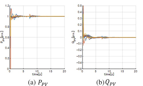
Figure 11. PV outputs (Case 3).
4.3. Simulation 2: with the subordinate power systems and induction motors
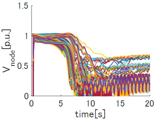
In this section, the simulation results with the subordinate power systems and the induction motors are shown. shows the internal phase angle differences between G1 and G10. In this power system, the node voltages recover and settle slower than those of the previous section (). Then the magnitude of the fluctuation is bigger than that of the previous section in Case 1. However, in Case 2, the fluctuation suppression can be achieved as in the previous section. This is because the PV reactive power outputs change responding to the voltage fluctuations thanks to the AVR (). On the other hand, in Case 3, the loss of synchronism occurs around 8 seconds. This is because the PVs consume reactive powers after the fault recovery as if the reactances of the VSG equivalent circuit consumed reactive power because does not change, which causes the voltage collapses ( and ). From these results, it is said that the VSG model based control with AVR is necessary in the power system with the poor voltage stability.
Figure 12. Internal phase angle differences.
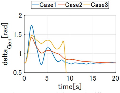
Figure 13. node voltages (Case 1, 0 ~ 5[sec]).
![Figure 13. node voltages (Case 1, 0 ~ 5[sec]).](/cms/asset/3f81d26e-a79e-4e71-97c2-b87c80e40136/tjee_a_1477094_f0013_oc.jpg)
Figure 14. PV outputs (Case 2).
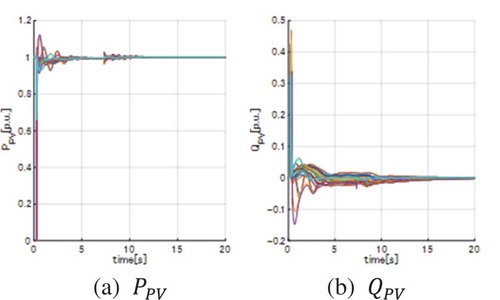
Figure 15. PV outputs (Case 3).
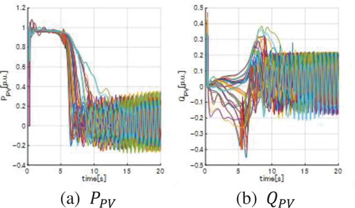
Figure 16. node voltages (Case 3).
shows the minimum rated output and the minimum rated capacity of energy storage per 1kW PV, which are necessary for achieving the VSG model based control in Case 2. The rated capacity is very small compared to the rated output. Therefore, capacitor is more suitable than battery for achieving the VSG model based control.
Table 2. Minimum rated output and minimum rated capacity of energy storage per 1kW PV.
5. Conclusions
In this paper, the proposed VSG model based control method has been presented. We have considered the d-q axes equivalent circuits of the VSG model to emulate the SG model and the AVR control.
In the simulation, the system stabilization effect of the proposed control in the large-scale power system has been confirmed. The proposed control is more effective than the PV output constant control of the PV. Also, without AVR, the VSG model based control does not work properly in the power system with the poor voltage stability.
As the future studies, the PV locations and the installed PV ratio, the variation of solar radiation amount, and the characteristics of the energy storage device will be considered in detail.
Disclosure statement
No potential conflict of interest was reported by the authors.
Additional information
Notes on contributors

Shun Nogami
Shun Nogami He received the B.S. from The University of Tokyo, Japan, in 2015 and M.S. in 2017. His research interests include the control of photovoltaic generations for power system stabilization.
Akihiko Yokoyama
Akihiko Yokoyama He has been with the Department of Electrical Engineering, University of Tokyo, since 1984 and is currently a Professor in charge of power system engineering.
Hiroyuki Amano
Hiroyuki Amano He has been with the Central Research Institute of Electric Power Industry, Tokyo, Japan, since 1998. Since 2016, he has been a Project Senior Researcher at the University of Tokyo.
Takashi Daibu
Takashi Daibu He received the M.S. in Electrical and Electronics engineering from Tottori University, Japan, in March 1995.
He joined Kansai Electric Power Co. Inc., Japan, in April 1995. He is engaged in power system control work.
References
- Driesen J, Visscher K. Virtual synchronous generators. In: Power and energy society general meeting - Conversion and delivery of electrical energy in the 21st Century, IEEE, 2008
- Sakimoto K, Sugimoto K, Shindo Y. Behavior of virtual synchronous generator at disconnection from grid. In: 2014 National convention record Japan: I.E.E; 2014. p. 437–438.
- Liu J, Miura Y, Ise T. Comparison of dynamic characteristics between virtual synchronous generator and droop control in inverter-based distributed generators. IEEE Trans Power Electron. 2016;31:3600–3611.
- Remon D, Cantarellas AM, Elsaharty MAA, et al. Equivalent model of a synchronous PV power plant. In: Energy conversion congress and exposition. IEEE; 2015.
- Van Wesenbeeck MPN, De Haan SWH, Varela P, et al. Grid tied converter with virtual kinetic storage. In: PowerTech 2009 IEEE Bucharest. 2009.
- Sakimoto K, Sugimoto K, Shindo Y, et al., Intentional Islanding operation of virtual synchronous generator based on current controlled inverter. The Papers of Joint Technical Meeting on “Power Engineering” and “Power Systems Engineering”; pp.39–43; 2014 Japan: IEE, PE-14-123, PSE-14-123.
- Taoka H, Sugiyama H, Kawai M, et al. Stablization of a power system by a distributed generation using the synchronous inverter. IEEE Trans Power Energy. 2016;136(2):129–136.
- Tamura J, Nakazawa C, Chihara I. A consideration on the accuracy of various synchronous machine models for power system transient stability analysis. IEEE Trans Power Energy. 2001;121(3):299–306.
- The investigation committee on control technologies of power electronic equipment for power system applications. Control technologies of power electronic equipment for power system applications. IEEJ technical report, No.1084; 2007
- Shirasaki K, Kitauchi Y. Fundamental influence of a power system condition on power system stability in transmission system with high penetration of renewable energy, System Engineering Research Laboratory Rep.No. R14013, Central Research Institute of Electric Power Industry; 2015
- The investigation committee on standardization models of power systems. Standardization models of power systems. IEEJ technical report, No.754; 1999