
 ?Mathematical formulae have been encoded as MathML and are displayed in this HTML version using MathJax in order to improve their display. Uncheck the box to turn MathJax off. This feature requires Javascript. Click on a formula to zoom.
ABSTRACT
Condensate pumps provide the motive force to deliver condensate from the hotwell to the deaerator storage tanks. Advanced Power Reactor 1400 (APR1400) is comprised of three 50% capacity motor driven condensate pumps with control performed by level control valves (LCVs). This configuration presents a challenge since the flow of condensate water is controlled by LCVs only. These LCVs are in throttled position in the pipeline where throttling of valves causes the loss of system efficiency by increasing the resistance to the flow. Generally, Variable Frequency Drives (VFDs) allow to operate motors and pumps at the precise speed needed for the process and energy saving. This paper investigates if there are any advantages when VFD is used to control the CPs and check the possibility of eliminating LCVs. Therefore, the NPP model was developed using Electrical Transient Analysis Program (ETAP) software and was benchmarked to APR1400. The analysis was performed with VFD installed and without VFD. The new approach for CP energy saving calculation using VFD was introduced and the results were confirmed by the ETAP model simulation results. The conclusion was drawn from the results whether the application of VFD for CPs has advantages for energy savings and economic benefits.
1. Introduction
The condensate and feedwater systems are designed to deliver the condensate water from the main condenser to the steam generator (SG). The condensate system consist of three 50% capacity motor-driven pumps (two operating and one standby) deliver condensate from the condenser hotwells to the deaerator through the condensate polisher, a steam packing exhauster, and three stages of LP feedwater heaters (). Condensate is provided to the SG blowdown regenerative heat exchanger for cooling [Citation1]. Three 50 percent capacity motor driven condensate pumps are vertical, multistage, centrifugal, and operate in parallel. During normal operation, two pumps are running [Citation2]. Each condensate pump (CP) supplies 11,000 gpm with 1100 ft of head (approximately 477psi) [Citation3].The third pump is prepared as a standby and starts automatically on the loss of one of the two operating pumps, allowing the plant to remain at 100 percent power [Citation2].The LCVs receive the control signals from the level transmitters which provide the indication and monitors the level of the condensate inside the two deaerator storage tanks (DSTs), A and B with capacity of 450,000 gal each. When the level is low or high the LCVs will control the flow by full opening or minimum opening. If the monitored level is below the minimum stored volume of 239,000 gal [Citation4], the standby CP will start for maintaining the DST’s capacity at the required level. In case of valve malfunction, the operator has the access to operate the LCVs manually.
Figure 1. APR1400 Condensate system.
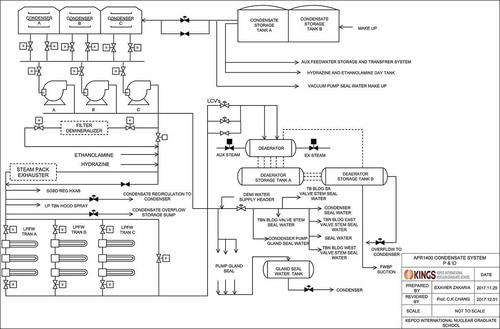
This configuration presents a number of challenges since the condensate flow to the DSTs is regulated by the LCVs only, which maintain an essentially constant deaerator storage tank water level at all plant operating conditions [Citation5]. These LCVs are in throttled position in the pipeline where throttling of valves causes the loss of system efficiency by increasing the resistance to the flow. Due to these reasons, the CPs was selected for this research. In this paper the VFD will be used to drive three condensate pumps and investigate the possibility of eliminating the LCV’s for the purpose of energy saving and extending the life of the pumps. The speed of the pump is adjusted by the VFD mechanism to shift the pump head curve to match the system resistance at the required system flow as shown in [Citation6].VFD offers the advantage of lower operating costs than throttle valve control, since the motor must only provide adequate energy to match the system resistance at the required system flow [Citation7]. The new approach for condensate pumps energy saving calculation using VFD will be introduced in section 3.2 and the results were confirmed by the ETAP model simulation results. Both results seemed to be very close.
Figure 2. Variable frequency drive control.
2. Literature review
By the 1980s, AC motor drive technology became reliable and inexpensive enough to compete with traditional DC motor control. The VFD became popular in accurately control the speed of standard AC induction or synchronous motors. With VFDs, speed control with full torque is achieved from 0 rpm through the maximum rated speed and, if required, above the rated speed at reduced torque. VFDs manipulate the frequency of their output by rectifying an incoming AC current into DC and then using voltage pulse width modulation to recreate an AC current and voltage output waveform. However, this frequency conversion process causes losses as heat in the VFD components that must be dissipated. The process also yields overvoltage spikes and harmonic current distortions.Nevertheless, with VFD control, the power input to the motor or pump varies with the cube of the speed, small change in speed can greatly impact the power required by the load [Citation8], as shown in [Citation9]. Therefore, the VFD provides continuous range process speed control as compared to the discrete speed control that gearboxes or multi-speed motors provide.
Table 1. Effects of reduced speed on required power.
Generally, Nuclear Power Plants (NPPs) are slow to adopt new technology. The major reasons are, it involves various modes of operations. Sometimes it is a challenge for the new technology to accommodate the requirements needed for each mode of operation and should be reviewed by various nuclear regulatory authorities before it accepted for its implementations. Another reason is for safety and system reliability. A recent trend in nuclear power plant upgrades has been the replacement of the motor-generator (MG) sets that drive the reactor circulating pumps with VFD. Siemens’ first application of VFDs in this industry began in 2000 with an installation of six VFDs at the Browns Ferry Nuclear Plant. The use of the VFD continues to expand, and upgrades were recently completed at several U.S. plants, including the Hatch Nuclear Plant in Georgia [Citation10]. In [Citation11], the amount of energy of 7,568,048.4 kWh was realized to be saved if VFDs were used to control the recirculation pumps of CANDU NPP. Also many researches have been done involving the replacement of VFD with equipment which requires speed and torque control. However most researches for industrial application of VFD, resulted in great benefits especially for energy and cost saving. In [Citation12], the eddy current drive was replaced with a VFD. With this modification the annual energy consumption was reduced from 439,065 kWh to 290,218 kWh and reduced the total annual electricity costs by 34%. Other case studies are the replacement of damper controls with VFD in Heating, Ventilation, and Air Conditioning (HVAC) system and the replacement of vacuum pump controls with a VFD in a diary facility. In both cases the energy and cost saving were realized. Despite the VFD’s challenges of producing harmonics and heat dissipation, VFD still seemed to have more advantages and economic benefit [Citation13–Citation15].
Many industrial facilities are still searching for the best ways to save the energy consumptions costs during the production. Thus, this research focuses on installation of VFD in the condensate system of APR1400 as one way of energy consumptions saving in the plant. Investigating if there are any significant benefits in energy and cost saving when the VFDs will be used to control three condensate pumps in the condensate system. The new approach of VFD energy saving calculation for condensate pumps will be introduced and then results were confirmed by the ETAP model simulation results. This approach distinguishes the difference with other previous work which has been published such as in [Citation16,Citation17].
2.1 Condensate pump motor starting method
Starting and control methods available for medium-voltage (MV) induction motors in the industry are continually changing in terms of application considerations due to the evolution of available products and changing characteristics of the machine and processes. These include direct on-line starting, primary resistance starting, star-delta starting, auto-transformer, soft starter and VFD [Citation18]. In the condensate system of APR1400, the CP motors are start and run by direct on-line method whereby these motors are connected to the 3 phases supply directly; while the flow of the condensate is controlled by the valves. Normally during the motor starting period, the starting motors appear to the system as small impedance connected to a bus. It draws a large current from the system, about six times the motor rated current, which therefore results in voltage drops in the system and impose disturbances to the normal operation of other system loads. Since the motor acceleration torque is dependent on motor terminal voltage, in some cases the starting motor may not be able to reach its rated speed due to extremely low terminal voltage [Citation19]. It also introduces the big mechanical stresses on the motor. VFD overcomes these challenges when is used as motor starting and control device by providing smooth motor starting. Thus the use of VFD in this research will be as an added advantage for the above addressed challenge, also for energy saving, precise flow and enhancing system efficiency.
3. Methodology
The following approaches were used for accomplishment of this study. The APR1400 NPP model was developed by using ETAP software ver.16.1.0. The load flow analysis and the short circuit fault current analysis were performed. The purpose of this analysis was to verify the impact of the design change. The model was benchmarked to APR1400 design input data. The analysis was performed according to the design criteria of NPP electrical systems. Then the field data were used to calculate an energy and cost saved by the two condensate pumps. Only two pumps was considered since during the normal operation the two 50% capacity pumps are operating and one is standby in case one of the two will stop. The results of the new approach method were compared with the ETAP simulation results obtained for credibility.
3. 1 ETAP model building
ETAP stands for Electrical Transient Analysis Program. Is a fully graphical electrical power system analysis program that runs on various windows operating systems. It can utilize real-time operating data for advanced monitoring, real-time simulation, optimization, and high speed intelligent load shedding. The electrical load lists was prepared with reference to Barakah NPP 1&2 Preliminary Safety Analysis Report (PSAR). Then single line diagrams of APR1400 division one and two was drawn in the ETAP by using the prepared load lists and reference drawings. The VFD specification data was proposed according to the input power and rating capacity of the condensate pumps as shown in . The condensate pump specifications are also shown in . The VFDs were also included in the diagram for condensate pump control. After the APR1400 model was developed, various analyses were carried out such as short circuit fault current, load flow analysis and harmonic analysis. Short circuit current analysis is very essential for the design of electrical systems because major equipment ratings are decided by that simulation. However, it has not direct related with this study. The purpose of performing the load flow analysis was to calculate the bus voltage, branch power factors, currents, and power flows throughout the electrical system. As well known, the main challenge in the VFDs applications is losses in the form of heat dissipated in its components during the frequency conversion process which causes the harmonics in the power system. The purpose of conducting the harmonic analysis was to determine its effects in the main transformer and the buses specific where VFDs were installed.
Table 2. The proposed VFD specification.
Table 3. Condensate pump specification.
Case 1: Simulation with the Current Operating Conditions (without VFD).
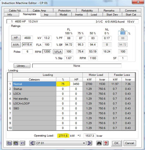
The VFDs in the model were set on the bypass mode for the purpose of disable the VFDs operations. The loading condition for the condensate pump was set to 75 % instead of 100%. This value was decided due to the load factor obtained by calculation using the field data. The load flow analysis simulation was performed and the results of motor input current, power and power factor were recorded. The CP input data in ETAP are shown in .
Figure 3. CP input data and loading condition in ETAP.
Case 2: Simulation with VFD
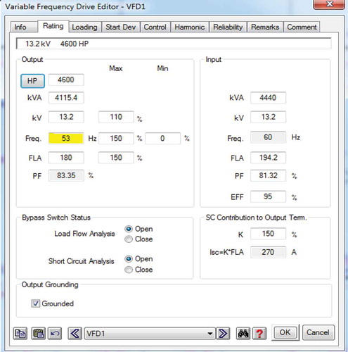
The VFD bypass switches were off so that to allow the CPs to be controlled by the VFDs, and the loading condition for the condensate pump was still set to 75 %. The load flow analysis simulation was performed and the motor input current, power and power factor were recorded. The VFD input and output data in ETAP are shown in .
Figure 4. VFD input and output data in ETAP.
3.2 By calculation (new approach method)
The field data was collected as shown below.
Motor Rating Data
BHP = 4600 HP (3432 kW)
V = 13.2 kV
IFL = 180 A (Motor name plate data)
N1 = 1180 rpm
Ƞ75% = 95.3 % (at 75% load)
PF = 87%
Current Operating Conditions data
Plant power at 100%
Pump operation = 80% hrs per year (assumption)
Motor operating current IL = 134.5 A (Field data)
CP Rated capacity = 12,700 gpm (801 L/s)
Flow rate (1CP) = 11,254 gpm (710 L/s), (Field data).
Electricity cost = 0.05 USD/kWh (assumption)
Rated head = 1,010 ft (308 m)
Run out head = 725 ft (221 m)
f1 = 60 Hz operating frequency
The and below illustrate the current and the proposed configuration respectively.
Figure 5. Illustrate the current configuration.
Figure 6. Illustrate the proposed configuration.
Case 1: The current Operating conditions
With reference to :
PF at 75% load = 87% (motor data sheet)
Case 2: When two Pumps operate with VFD
With reference to , VFD will control the CP at reduced speed with the flow rate of = 11,254 gpm.
By applying the affinity theory for the centrifugal pumps:
Where: Q is the flow rate, N is the impeller or rated speed, H is the head, T is the rated torque and HP is Power.
The frequency at the reduced speed will be calculated by the following formula.
Operating head will change due to change of speed
The above result in (7) should be confirmed if meet the minimum requirement of run out head of the system (221m).
Required Power, P2 α
PF at low load = 84 % (from ETAP simulation)
Annual energy saving = 5,045.76 MWh x 2 = 10,091.52 MWh for two CPs
Annual cost saving = 720 kW x 24hr x 365 days x 0.8 × 0.05 USD/kWh = 252,288 USD for one CP
Annual cost saving = 252,288 x 2 = 504,576 USD for two CPs
3.3 Harmonic analysis
As well known, the main challenge in the VFDs applications is harmonics in the power system generated by the distortion of the current wave during rectifying and inverting process. The presence of harmonics can give rise to a variety of problems including equipment overheating, deteriorating performance of electrical equipment, the incorrect operation of protective relays and interference with communication devices. Due to these reasons, the harmonic phenomena of the power system was modelled and analysed by using ETAP software for determination of its effects in the main transformer and the buses specific where VFDs were installed. ETAP modelled accurately various power system components and devices such as frequency dependency, nonlinearity and other characteristics under the presence of harmonic sources. In ETAP software, the harmonic load flow study was performed and the results were also recorded.
4. Results
As mentioned earlier, the new approach of energy saving calculation for condensate pumps has been introduced in this paper when VFD will be used to drive some condensate pumps for the purpose of energy saving, and its results were compared with the ETAP model results as justification of its validity and credibility. Therefore, the results obtained are listed below.
4.1 Simulation results
Case 1: Simulation results with the Current Operating Conditions (without VFD).
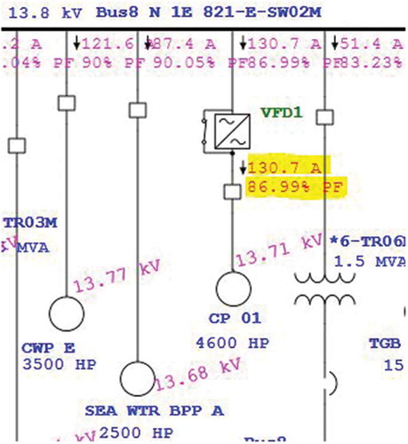
The was captured during the load flow simulation with the current operating conditions. The voltage level of the motor terminals were verified to check if meet the design requirements. The motor input current and power factor highlighted in yellow colour were recorded.
Figure 7. The results of simulation in the current operating conditions.
Case 2: Simulation with VFD
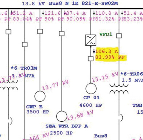
The represents the load flow simulation results when VFD was installed in the ETAP model for controlling the condensate pumps. The voltage level of the motor terminals were verified. The input motor current and power factor highlighted in yellow colour were recorded.
Figure 8. The simulation results with VFD.
4.2 Calculation results
The results obtained from the calculations were summarized in the .
Table 4. Shows the calculation results.
4.3 Harmonic analysis results
The harmonic analysis results are shown in the and below.
Table 5. Harmonic results in bus N 1E 821-E-SW02M.
Table 6. Harmonic results in the main transformer.
5. Discussion
In this section, results have been compared for the purpose of finding out if the new introduced method has the similar results with the ETAP simulation results. The results are mainly divided into two parts which are, when the condensate pumps are operating with the present condition (without VFD) and when VFDs were installed. shows the summarized comparison table, whereby in the present operating condition, the motor input current from the field data (134.5 A) is closer to that of simulation results of 130.7 A, thus the small difference of 3.8 A (3%) has been noted. The power factor from the motor data sheet is exactly equal with that from the simulation results of 87%. The motor input power result obtained from the calculation method has a slight difference of 37 kW (1%) with the simulation result. However the difference of 87 kW (4%) for motor input power and 9 A (8%) input current has been noted respectively for the case when the proposed VFDs were installed. The cause of these implications might be due to some assumptions used during the calculations. Meanwhile, the ratios results give the significant equal ratios for efficiency and slight differences for current and power ratios as shown in . This implies that the proposed method for calculating energy saving in the condensate pumps are credible and the amount of energy saved with VFDs are reasonable. As shown in , the amount of 720 kW (27%) can be saved for one condensate pump and a total of 10,091.52 MWh can be saved annually which cost 504,576 USD. However, the calculation of rate of return (RR) or payback period is out of scope of this paper. The advantage of the proposed approach is that, the minimum allowable head can be estimated see (7) to check the requirement regarding the run out head of the system for VFD’s application on the condensate pump.
Table 7. The comparison between the simulation results and the results obtained from the calculation.
On the other hand the results of the total harmonic distortion (THD) in the bus are very minimum (see ) and seemed no harmonic effects in the main transformer (see ), this indicates that no significant harmonic effects be introduced in the electrical system due to the application of VFD in the condensate pumps thus, the IEEE Std 519–1992 requirements has been met [Citation20].
Another implication arise on the load factor calculated by using the field data seemed to be 75% than expected of 100% since according to the literature the three condensate pump are 50% capacity motor driven pumps. This may be influenced by the design margin of the motors. It has negligible effects during the experiment since the same load factor was used in both, calculation and in ETAP simulation.
The main purpose for application of VFDs are as mentioned in other previous works such as,it can provide the precise speed control for condensate system when is required, the VFD provides minimum motor real power demand about 1955 kW compared to 2675 kW without VFD(calculation results in ). This helps in saving system energy and improves the efficiency. Also the VFDs provides flexibility in torque, the load can be easily accelerated or decelerated as slowly as desired that is ideal in limiting mechanical stress on bearings, seals, shaft, and vibrations; which will increase the life span of the CP motors. Maintenance savings arise and the plant running costs can be reduced.Furthermore the proposed VFDs has in-built power factor correction and motor protection functions which can improve system power factor and provide protection for the condensate pump motors. The bypassed capability also provides maximum flexibility. In case of fault in the VFD units, the bypass switch will be activated and the system will operate as in previous.
6. Conclusion
This study indicates that the significant energy saving is real in the application of VFDs for condensate pumps. Most notably, the paper has a major contribution to our knowledge for proposing the new approach of calculating the energy saving in the condensate pumps, this distinguish the difference between the previous works which has been done in the application of VFDs in the NPP.
Our results meet the required design criteria for electrical systems in NPP. The method shows that 10,091.52 MWh and the cost of 504,576 USD can be saved significantly when the VFDs will be used to drive the condensate pumps of APR1400. Therefore, VFDs can be installed in the APR1400 to drive the condensate pumps. Since the installed VFDs have bypassed capability, it is suggested that no need to eliminate the level control valves (LCVs), they will be used as an option when the VFDs bypass mode are activated during its maintenance or fault condition.
However, the new proposed method provides the estimated values for cost saving unless other factors such as VFD cost, installation cost, maintenance cost and the available space must be taken into consideration. Other NPP regulatory requirements should also be considered before the VFD’s application.
Acknowledgments
This research was supported by the 2017 Research Fund of the KEPCO International Nuclear Graduate School (KINGS), Republic of Korea.
Disclosure statement
No potential conflict of interest was reported by the authors.
Additional information
Funding
Notes on contributors
Exavier Zakaria Barie
Exavier Zakaria Barie is a holder of the master of engineering in Nuclear Power Plant Engineering from KEPCO International Nuclear Graduate School (KINGS) at Ulsan, the Republic of Korea since January 2018. He obtained his bachelor of engineering degree in Electrical and Electronics from Mbeya University of Science and Technology (MUST), the United Republic of Tanzania in 2013. Also, he is a holder of Full Technician Certificate in Electrical Engineering from Dar es Salaam Institute of Technology (DIT), the United Republic of Tanzania since 2002. He has been employed as a nuclear instrumentation technician at Tanzania Atomic Energy Commission (TAEC) since 2006. Currently, he is working as assistant nuclear research engineer since 2013.
Choong-koo Chang
Choong-koo Chang received M.S. in Electrical Engineering from Inha University in 1990, and Ph. D degree in Electrical Engineering from Myongji University in 2001. He participated in Younggwang NPP 3&4 and Ulchin NPP 3&4 design project as an electrical system engineer from 1985 to 1993 at KOPEC. From 1993 to 1998 he worked as a senior engineer for the plant control, and automation business team of Samsung Electronics. As an Executive Vice President and CTO at Sangjin Engineering from 2001 to 2012, he designed the electric power systems for nuclear power plants, thermal power plants, and combined cycle power plants. Since 2013, he serves as a professor in the NPP Engineering Department of KEPCO International Nuclear Graduate School (KINGS). His research interests are planning, design, and operation of the electric power systems for power plants.
References
- Advanced Power Reactor 1400 Design Control Document. (2013). KEPCO & KHNP Chapter 10, pp.4–37.
- Advanced Power Reactor 1400 Design Control Document. (2013). KEPCO & KHNP Chapter 10, pp.4–41.
- Westinghouse Technology Systems Manual Rev.0403. (2011). Westinghouse technology Section 7, pp.2–8.
- Westinghouse Technology Systems Manual Rev.0403. (2011). Westinghouse technology Section 7, pp.2–14
- Advanced Power Reactor 1400 Design Control Document. (2013). KEPCO & KHNP Chapter 10, pp.4–45.
- Condensate pump application and maintenance guide. Palo Alto, California: EPRI; 2000. p. 4–8.
- Condensate pump application and maintenance guide. Palo Alto, California: EPRI; 2000. p. 4–7.
- Variable Frequency Drives, Energy Efficiency Reference Guide. CEATI International; 2009. p. 6–7.
- Variable Frequency Drives, Energy Efficiency Reference Guide. CEATI International; 2009. p. 53–54.
- Harshman M (2010) Variable-Frequency Drives Upgrade Reactor Circulating Pumps. [online] POWER Magazine. [cited 2017 Aug 20]. Available from: https://www.powermag.com/variable-frequency-drives-upgrade-reactor-circulating-pumps/
- LaurentiuCiufu P. (2015). Introducing energy efficiency in nuclear power plants by using variable medium voltage frequency drives. In: 9th International Symposium on Advanced Topics in Electrical Engineering. Romania: IEEE,pp.873–876.
- Variable Frequency Drives, Energy Efficiency Reference Guide. CEATI International; 2009. p. 71, 72, 75.
- Miller P, Olateju B, Kumar A. A techno-economic analysis of cost savings for retrofitting industrial aerial coolers with variable frequency drives. Energy Conversion and Management. 2012;Volume 54(Issue 1):81–89.
- Bhavana M, Vishwanath H, (2015). Energy conservation using variable frequency drives of a humidification plant in a textile mill, In: International Conference on Power and Advanced Control Engineering. India: IEEE.pp.90–94.
- Zhang L, Zhuan X (2017). Optimal operation scheduling of multiple pump units on variable speed operation with VFD in the east route of south-to-north water diversion project. In 36th Chinese Control Conference. China: IEEE, pp. 2818–2823.
- Ciontu M, Popescu D, Motocu. M (2010). Analysis of energy efficiency by replacing the throttle valve with variable speed drive condensate pump from E.C. Turceni. In: 3rd International Symposium on Electrical and Electronics Engineering. Romania: IEEE, pp.293–297.
- Sheen J (2009). Economic Feasibility of Variable Frequency Driving Pump by Fuzzy Financial Model. In: Fourth International Conference on Innovative Computing, Information and Control. Taiwan: IEEE, pp.934–937.
- Medium Voltage Application Guide 710-12280-00A. New Zealand: AuCom Electronics Ltd; 2012. p. 10–18.
- ETAP 16.1 User Guide. Southern California: Operation Technology Inc; 2017. p. 21–31.
- IEEE Guide for Recommended Practices and Requirements for Harmonic Control in Electrical Power Systems. (1993). IEE Standard 519-1992, pp.79–92.