
ABSTRACT
This article introduces 3Cat-1, the first project of the Technical University of Catalonia to build and launch a nano-satellite. Its main scope is to develop, construct, assemble, test and launch into a low Earth orbit a CubeSat with seven different payloads (mono-atomic oxygen detector, graphene field-effect transistor, self-powered beacon, Geiger radiation counter, wireless power transfer (WPT), new topology solar cells and WPT experiment), all fitted in a single-unit CubeSat. On one hand, this is mainly an educational project in which the development of some of the subsystems is carried out by undergraduate and postgraduate students. The satellite demonstrates its capabilities as a cost-effective platform to perform small scientific experiments and to demonstrate some of the new technologies that it incorporates.
KEYWORDS:
Introduction
The 3Cat-1 (read “cube-cat one”) is the first satellite of the Technical University of Catalonia (Jove Casulleras Citation2015) (Universitat Politècnica de Catalunya (UPC) BarcelonaTech). Initially conceived as an educational project (Bragós et al. Citation2012), the 3Cat-1 is a single-unit (“1U”) nano-satellite developed in compliance to the CubeSat standard. The spacecraft integrates up to seven different payloads, five of which are aimed at carrying out scientific experiments and perform technology demonstrations, namely:
A micro-electro-mechanical system (MEMS)-based monoatomic oxygen detector
A couple of coils to test wireless power transfers in the presence of plasma
A graphene field-effect transistor (GFET)
A new topology of solar cells
An energy-harvesting experiment that relies on temperature gradients in the spacecraft walls
With these, and two additional payloads based on commercial-off-the-shelf (COTS) components (an optical camera and a Geiger counter), the 3Cat-1 is ultimately designed to explore the capability of this class of spacecraft and to identify the need for standardized software and hardware interfaces for the development of future nano-satellite missions.
The integration of the payloads of this mission in an 1U nano-satellite has posed a significant challenge both in terms of mass and volume and in terms of energy and subsystem management. In order to overcome the operability issues that arise from the fact that the spacecraft has multiple payloads with heterogeneous system constraints (e.g. execution cycles, power consumption and data generation volume), the 3Cat-1 also encompasses an onboard autonomous management system, which is able to generate mission plans of action without human intervention. This mission planning system (MPS), fundamentally composed of a task scheduler, is capable of autonomously planning the payload activities that fulfill the mission goals while safely controlling the system resources (namely energy, data storage and communication bandwidth).
This article presents the 3Cat-1 mission, describes its payloads and basic subsystems, and addresses system integration both at the hardware and software level. In addition, this article shows the autonomous management approach implemented onboard in this spacecraft.
Mission goals and contributions
The goal of the 3Cat-1 mission is twofold. On one hand, the spacecraft aims at exploring the capabilities of 1U nano-satellites. Nowadays, technology miniaturization allows the design of small devices that can study physical phenomena, are highly integrated and present very low-power consumption. Miniaturized sensors and actuators and embedded systems (i.e. high-performance, yet low-power microprocessors and system-on-chips) have been one of the enablers for nano-satellite missions and have provided small spacecraft with capabilities that can be scientifically valuable. With the advent of inexpensive single-board computers and other COTS subsystems, the efforts in small spacecraft development are focused on the integration of components (e.g. sensors and modules) and payloads. In this respect, one of the fundamental activities in the 3Cat-1 initiative has been devoted to maximize the number of payloads and functionalities of a nano-satellite in order to demonstrate their potential and foster innovative concepts in the integration of spaceborne instruments and subsystems.
On the other hand, the 3Cat-1 has been designed to perform Earth observation and space research activities. The satellite has sensing capabilities provided by its payloads and onboard sensors that include the following types of measurements of the environment:
Earth’s magnetic field – provided by the attitude determination and control subsystem (ADCS)
Earth imagery in the visible spectrum – provided by a low-resolution camera
Detection of ionized particles – provided by a Geiger counter
Presence and density of monoatomic oxygen in the ionosphere – provided by a MEMS-based detector for this chemical element
The design and development of 3Cat-1 has been carried out at UPC’s Nano-Satellite and Small Payload Laboratory (NSSPL), a facility with all the necessary testing equipment to validate and qualify nano-satellites up to six units (6U): a thermal vacuum chamber, a Sun simulator, a shake table and an Earth magnetic field generator. In addition to several MSc and PhD students, the NSSPL welcomes more than 30 undergraduate students every year, who participate in the research activities and subsystems design and development as part of a regular course within their BSc curricula. Notwithstanding the number of commercially available modules that allow to implement the essential subsystems of a nano-satellite (i.e. communications, attitude control and determination, command and data handling and energy management), most of the subsystems in 3Cat-1 have been designed ad-hoc and have used mostly COTS components and modules, which have been self-qualified in the laboratory facilities. This design choice has been motivated both by integration issues (i.e. volume minimization, mechanical compatibility and reduced power consumption), for educational purposes, and to shorten development times. Whereas the design, implementation and test of the spacecraft and its main subsystems have been performed by graduate and undergraduate students of the NSSPL, some of its payloads and experiments have been developed, advised or outlined by research groups at UPC or in collaboration with international institutions. Sections on “In-orbit operations”, “Main platform subsystems” and “Payloads” describe the subsystems and payloads and acknowledge their contributors.
Mission analysis
Given the fact that the 3Cat-1 will be launched as piggyback of a larger satellite, its mission has been designed to avoid being too dependent on the orbit. For completeness of the following sections of this article, it is important to mention that the final orbit in which it will be deployed is a 550–650 km elliptical polar orbit.
Mass
The CubeSat Design Specifications guideline (California Polytechnic State University Citation2009) limits the mass of the satellite to a maximum weight of 1.33 kg. 3Cat-1 was designed to weigh less than 1 kg to consider design safety margins, to be able to include radiation shielding and to balance the center of masses, which must be within a 1-cm radius sphere around the geometrical center. 3Cat-1’s total mass is 1292 g. However, satellite mass excluding balancing and shielding is as low as 790 g. It has allowed the possibility to change aluminum shielding by brass shielding, much denser, but better for shielding purposes. Additionally, while aluminum is extremely difficult to solder, brass can be easily soldered so balancing weight masses can be soldered on it.
Data
Assuming a single ground station, located in Barcelona – Spain, to have access to the satellite, the access time for the data budget is expected to be 604 s on average per pass, having a maximum pass of 772 s. The communications used onboard 3Cat-1 have a nominal data rate of 9600 bps, which yields an average of 652,000 bytes of data downloadable per pass, when considering an optimal transmission protocol with an efficiency of 90%. On the other hand, the amount of data generated is shown in . It can be clearly appreciated that most of the data are being generated by the optical camera. Data link capacity is larger than the data budget.
Table 1. Data budget.
Thermal
To maximize the stability of the satellite, all the external faces are gold covered, while all the internal ones are blackened such to have high emissivity surfaces. This is the configuration that has the minimum thermal excursion if the satellite goes in shadow. The beta angle of the orbit is not known until the satellite has been launched. The most extreme temperatures are withstood by the solar panels: from 291 to 304 K on a beta 90° orbit; from 250 to 310 K every orbit on a beta 0°, where battery heaters must be turned on to avoid having the batteries frozen.
Power
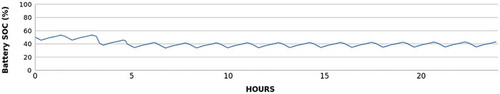
Power budget is extremely critical in a single-unit CubeSat, accomplishing it has been one of the main issues when developing 3Cat-1. and show the power consumption of each subsystem and battery state-of-charge (SoC) for a beta angle 90°, while and show the same analysis for a beta angle 0°. The power budget of the second case cannot be kept as desired, as the communication subsystem requires very high power, and the battery heaters must be turned on periodically.
Figure 1. Simulated power consumption for each subsystem for a 90° beta angle.
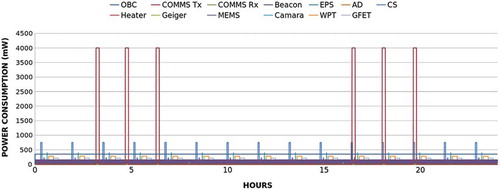
Figure 2. Simulated battery state of charge for a 90° beta angle.
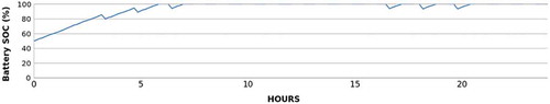
Figure 3. Simulated power consumption for each subsystem for a 0° beta angle.
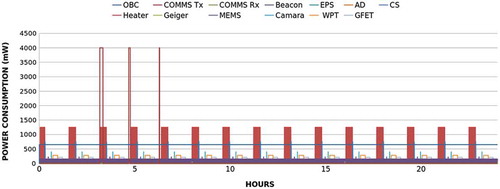
Figure 4. Simulated power consumption for each subsystem for a 0° beta angle.
Radiation
A basic radiation analysis was performed in order to assess the criticality of possible damage caused by ionized particles as well as to characterize component life span. The radiation analysis follows the steps proposed by Sinclair and Dyer (Citation2013), and it is performed using SPENVIS (Heynderickx et al. Citation2000).
The results showed that a cover glass is required to protect the solar panels. The results suggest to have a minimum thickness of 100 µm of cover glass to prevent hard damages of the solar cells and extend their life expectancy. The results also concluded that in the absence of cover glass, the power available from the solar panels would decrease to 50% in 4 months.
The effects studied on electronic components (a Samsung 16 M dynamic random access memory is used as reference) showed that at least a bit will fail once a year. Multiplying it by the number of microcontrollers available in the satellite assures at least a failure every month. In order to mitigate the functional misbehaviors caused by ionized particles, 3Cat-1 includes a hard-reset circuitry which periodically resets the whole spacecraft and clears temporary bit-flips. This hard reset system is implemented in the electrical power subsystem, and it is detailed in the section on “Electric power subsystem”.
In-orbit operations
Traditionally, the operation of satellite missions has relied on sequences of commands sent from one or more ground stations that controlled and monitored the spacecraft. When satellites pass over their ground stations, they receive sequences of time-tagged telemetry commands whose execution is statically scheduled at ground. Those commands, which may include a myriad of requests and configuration changes, program the activities of the spacecraft based on plans of action generated at the ground segment. Modern satellite approaches, however, are moving toward a more autonomous concept where ground operators upload mission goals instead and allow the spacecraft to autonomously schedule its activities to meet those goals (de Novaes Kucinskis and Ferreira Citation2013; Wojtkowiak et al. Citation2013). Mission goals inherently encapsulate complex and flexible command sequences that will be decomposed onboard and do not necessarily have a fixed execution time. Moving the mission planning capabilities from the ground to the space segment not only allows the spacecraft to autonomously schedule the execution of tasks taking into account resource constraints and goal specifications, but it also introduces the ability to self-assign mission goals based on onboard data analysis and to react quicker to unexpected events and faults.
There are many different factors that suggest that nano-satellites should also be provided with a certain degree of autonomy. Their limited observability and communication restrictions preclude ground operators from downloading fine-grained state and housekeeping data and hence introduce uncertainties in MPS on-ground. Conversely, autonomous spacecraft that are capable to plan their activities not only are more robust, responsive and resilient because they can react to unexpected failures instantaneously, but could also improve the system performance by minimizing periods of inactivity (Iacopino and Palmer Citation2013). This concept, the benefits of which have been validated in previous missions (e.g. EO-1 (Chien et al. Citation2005)) and studies (Chien et al. Citation2014), has demonstrated to be a feasible alternative for nano-satellite spacecraft as well (Beaumet et al., Citation2011).
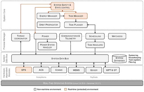
Given the benefits of autonomous nano-satellites, the 3Cat-1 has been designed to follow the same operability precept. In order to allow the spacecraft to autonomously plan its activities, an onboard task scheduler has been integrated within the onboard and data handling subsystem. With this, the autonomy system of the 3Cat-1 is composed of the components listed below and shown in .
Orbit propagator: it calculates the spacecraft trajectory in order to determine the satellite location (with respect to Earth coordinates).
Energy manager: based on static models and the orbit propagation, this component generates a prediction of energy income for a predefined scheduling window. It also calculates ground station access times;
Priority-based multi-resource task planner: based on the predicted power input, the orbit trajectory, the current battery SoC and system constraints (e.g. maximum instantaneous power deliverable to payloads, available storage, etc.), this component takes a list of activities (or tasks) and schedules them in accordance to the mission goals set by ground operators (e.g. do a picture when passing over Barcelona; measure radiation in a certain position of the orbit). The task planner is developed with Constraint Programming and written in Prolog.
Process manager: it is a robust executive that decomposes the autonomously generated mission plan into a set of internal commands and routines.
Figure 5. Mission operational state transition scheme.
Figure 6. Subsystem activity temporal diagram.
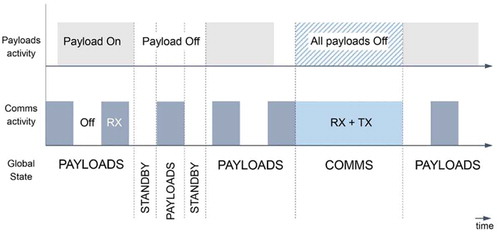
Figure 7. Block diagram of the electrical power system.
Figure 8. Software architecture components and hierarchical layers.
With this set of components, the mission operates in the modes shown in , which do not include mission commissioning and the initial deployment steps. The main modes of operation are payloads and communications. In the first one, the generated schedule is executed while no contact with Earth is possible. The communications subsystem (COMMS) is enabled during the payloads state although the subsystem is duty cycled to reduce its power consumption. In the communications state, the satellite reserves all its resources (i.e. power, CPU) to perform the commands that arrive from the ground segment. Note that during the inactivity periods of the payloads state in which no activity has to be executed and the COMMS is halted, the satellite activates a low-power mode to save energy ().
During the schedule state, the autonomy system of the spacecraft generates a mission plan for a given scheduling window that takes into account the next ground access time (). Because of the computational complexity of the final task scheduler algorithm implementation and the low computational resources of the onboard computer (OBC), this process could require unacceptable times to compute a solution or render the spacecraft without memory. In order to reduce the mission risk, the autonomy system is overridden by ground-generated mission plans and will be activated as a software-payload in a mission-safe and controlled environment (i.e. restricted memory and computation time).
Main platform subsystems
Electric power subsystem
The electrical power system (EPS) is one of the critical systems of 3Cat-1. The EPS is involved in the generation of electrical energy, its storage in the batteries, the regulation and control of the power and the distribution in power buses. The architecture used in 3Cat-1 uses two typologies of solar cells, which force the need of boost converters before the battery charger. The battery charger regulates the power provided, and the one stored in the battery, while it also hosts the hard reset circuitry of the satellite. The output power of the battery charger is distributed to the satellite through the unregulated power bus. Each subsystem has its own point-of-load (POL) to adapt the power available to its needs and protect each subsystem from over-current and latch-up effects. Finally, all the POL can be enabled or disabled from the microcontroller onboard the EPS. This microcontroller receives the orders to enable or disable POL from the OBC. The block diagram of the EPS is shown on .
Onboard data handling
The 3Cat-1 integrates a PortuxG20 single-board computer, manufactured by Taskit GmbH, as the main OBC of the mission. With an ATM91SAM9G20 CPU (ARM9 core) running at 400 MHz with 64 MB of synchronous dynamic random access memory, the OBC interfaces with the rest of the satellite subsystems and payloads through an universal asynchronous receiver/transmitter and serial peripheral interface digital buses. The onboard data handling software architecture handles the communication protocol with each subsystem device (microcontrollers, transceivers and the like) and generates the data that they may require (e.g. telemetry packets, configuration data for payloads.)
The software architecture is deployed as a set of processes, libraries and drivers and is deployed on top of a dual-kernel operating system: a mainline Linux kernel patched with the Xenomai real-time hypervisor (Araguz Citation2014). With the soft-real-time capabilities and services offered by this RTOS, the architecture has been partially implemented under the real-time environment (critical system-wise modules and applications) and partially as nonreal-time processes (noncritical payload and subsystem modules). Divided into four hierarchical layers (Beaumet et al., Citation2011), the software architecture components are depicted in .
Communications
The COMMS is responsible of the information transmission and reception with the ground station. The ground station downloads data gathered by the numerous experiments performed on board 3Cat-1 and uploads the appropriate telecommands to the satellite. Also, the status of the nano-satellite along with its identifier needs to be constantly transmitted to the Earth for any ground stations that may want to track the CubeSat. The former is performed by the main transceiver, while the latter is performed by a beacon. Moreover, in 3Cat-1, there is an extra beacon that performs a similar function as the normal one, but it is a payload itself, powered by the Peltier cell, and totally independent from any other subsystem, including the EPS.
These signals are then combined using a three-way-0° power combiner and then split into a two-way-90° power splitter to create the circular polarization. These circularly polarized waves are then fed to the baluns and the dipole antennas. The block diagram of the COMMS is shown in .
Figure 9. Block diagram of the communication system.
Attitude determination and control system
The ADCS is used to have information and control of the position and rotations of 3Cat-1. The ADCS uses a passive system to stop the rotation and stabilize the satellite in a desired orientation, and an active one to orient the satellite to a desired target. The idea behind using a passive system is to increase the reliability of the mission as well as to decrease the power consumption. The passive system is made using a permanent magnet to point to a predefined direction and high magnetic permeability materials to dump the oscillations. The active system improves the pointing accuracy of the camera to the Earth when a picture is taken. This system is only available when the passive system has damped enough the rotation of the satellite. In addition, magnetic sensors are used to have a reference of the 3Cat-1 attitude, and they are required for the active control.
This hybrid configuration allows to have the inclination referenced to the Earth’s magnetic field, while at the same time allows another 30° of tilting if the active controller is activated.
Payloads
Eternal self-powered beacon demonstrator
The eternal self-powered beacon demonstrator (Jove-Casulleras et al. Citation2014) is one of the payloads of 3Cat-1. It is a totally independent system that should work even in a catastrophic failure of all the subsystems on 3Cat-1, as it does work neither with the EPS, nor with the OBC, and it has its own COMMS. It works with a variable duty cycle depending on the temperature gradient between the inner part of the satellite and the solar panels. This duty cycle of the beacon is at the same time a temperature gradient sensor.
Powering a spacecraft beacon subsystem with a self-powered energy source increases the mission reliability. However, the low solar flux received and the lack of convection make difficult the possibility to obtain enough temperature gradient to make thermoelectric generators attractive. The selection of the appropriate location can make them useful to run low-power systems like a beacon.
The energy harvested to send a beacon signal cannot offer a continuous working cycle. The solution used in 3Cat-1 is based on directly interfacing sensors, which link sensors to microcontrollers without a signal conditioning circuit (or an analog-to-digital converter) on the one side, and energy-harvesting systems on the other side. These are two key enabling technologies to create the self-powered beacon signal. In 3Cat-1, both technologies are concurrently combined.
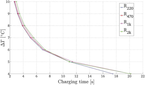
Harvesting energy from a low temperature gradient requires a very low voltage step-up power conversion circuit, which has been designed based on the principle of function of the Joule Thief circuit (Bohan Citation1988). shows the power supply system-level block diagram, which consists of three main circuit blocks interconnected to deliver a stable DC voltage to supply a variable load. The step-up block (left) conditions and extracts the power by increasing the voltage provided by the Peltier cell to charge the storage capacitors (center). The storage capacitor is dimensioned as a function of the power requested by the output load. Once the voltage of the capacitor reaches a certain threshold (Vth,max), an hysteresis comparator enables the voltage regulator circuit (block on the right), which provides the stabilized output voltage (Vcc) until the capacitors are discharged below the minimum threshold established by the reference voltage (Vref) in the comparator. This process is cyclic and is repeated indefinitely, with a frequency that depends upon the load of the circuit and the temperature gradient of the Peltier cell. From the tests performed on the circuit implemented, it was observed that a minimum voltage of 0.4 V is required to operate the step-up circuit and start switching the transistors to charge the capacitor of the Joule Thief circuit.
Figure 10. Self-powered beacon system-level block diagram.
In order to validate the model, different measurements with different resistors simulating the power consumption of the transmitter circuit have been carried out (). The minimum temperature gradient that can be sensed by the self-powered beacon and sensor is 4°C. This is due to the fact that the current leakage of the capacitor, comparator and voltage regulator is larger than the current supplied by the harvesting circuit.
Figure 11. Charging time vs. temperature gradient for a 2600 μF capacitor.
CelSat solar cells
One face of 3Cat-1 has a solar panel made out of 11 CelSat solar cells (Ortega et al. Citation2013), which are electrically connected in series for two main purposes: (a) to study the impact of space environment on electrical behavior of crystalline Si solar cells. Interdigitated back contact (IBC) solar cells are very adequate to this objective due to its sensitivity to surface and bulk recombination that can increase dramatically with radiation damage and (b) to form part of the satellite power subsystem combined with the Spectrolab solar cells.
However, mission success cannot be risked by CelSat solar panels and its fast degradation with space environment. A compromise is acquired using 400 μm of Al2O3 coverglass.
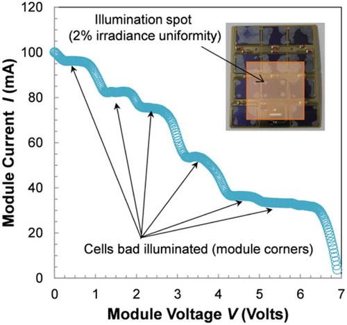
Preliminary electrical measurements are made using a solar simulator (model ORIEL 94021A) under standard test conditions (AM 1.5G spectrum 1 kW/m2, T = 25°C). Open circuit voltage Voc increases with the number of solar cells in series. The current–voltage characteristic curve exhibits some drops and plateaus at different voltages (see ) as a consequence of a nonuniform module illumination. ORIEL 94021A has a beam size (2% irradiance uniformity) of 5 cm, smaller than the solar panel size. Out of these beam limits, irradiance drops drastically. Hence cells out of the beam are poorly illuminated and the Schottky diodes partially bypass them, indicating a proper performance of these protecting devices.
Figure 12. Current vs. voltage graph of the CelSat module.
MEMS-based monoatomic oxygen detector
Atomic oxygen is a very reactive chemical element present in the lower thermosphere. Comparisons between day and night pictures at the beginning of in-space observation showed that the residual atmosphere was interacting with the materials. Space Shuttle engineers noticed that the Kapton that was protecting the cameras had been altered during the flight. It was concluded that degradation was caused by oxidation of organic materials through high-velocity collision with atmospheric atomic oxygen (Leger Citation1983).
Atomic oxygen is formed in low Earth orbit (LEO) environment through photo-dissociation of diatomic oxygen (O2). Between the altitudes of 180 and 650 km, atomic oxygen is the most abundant species (NASA Citation2014). The MEMS atomic oxygen detector is based on a cantilever membrane that vibrates when excited by temperature (Maine Citation2010; Ricart et al. Citation2010). This temperature excitation is due to pulsed currents applied on it. A small mass of polymer (pentacene) is placed over the membrane. The presence of atomic oxygen is related to the mass erosion of the polymer. To calculate this mass erosion, the membrane is forced to vibrate, and the resonant frequency of the system is sensed. The variation of the resonant frequency is inversely proportional to the square root of the mass of the cantilever. Therefore, the mass lost by the polymer is obtained.
Graphene transistor in-space characterization
It is desired to study the effects of space environment over GFET technology. GFET technology is quite recent, with the first functional device being manufactured in 2010; however, it is expected that eventually GFET technology will replace the current Si-based one. To achieve this, GFET technology has to be first widely tested (Iannazzo et al. Citation2015). The GFET experiment generates the characteristic DC curves of the transistor. The behavior and the evolution of these curves during the mission and the accumulated radiation dose will indicate how this technology is deteriorated over time. The curves are generated applying a known voltage between drain and source, and at the same time between gate and source, to evaluate the current passing through drain terminal. Varying both, a voltage–current map is obtained and therefore, the behavior of the transistor is obtained.
Plasma effects on wireless power transfer (WPT)
The purpose of this technology demonstrator payload is to characterize the effects of space plasma upon the performance of resonant inductive coupling wireless power transfer [RIC-WPT] systems, in the context of future WPT-enabled fractionated satellites and small satellite swarms (Porter et al. Citation2014). RIC-WPT systems, which consider wireless exchange of power between a transmitter and a receiver based on magnetic field, can potentially achieve high efficiency power transfer for mid ranges by virtue of coupling highly resonant and tuned transmitter and receiver resonators. This notwithstanding, WPT systems in turn exhibit high sensitivity to interfering objects (Bou-Balust et al. Citation2015), and it is hence speculated that space plasma can alter the physical medium, thereby impairing the WPT system performance – namely, through frequency detuning. Accordingly, a frequency- and size-downscaled, deployable and planar printed circuit board-embedded self-resonant coils RIC-WPT system has been included in 3Cat-1. The technology demonstrator incorporates an electronic fronted to drive and automatically characterize the system, in particular its transfer function, to quantitatively measure the performance degradation across time when orbiting with the WPT system being exposed to space.
Camera
The camera payload was the first experiment proposed for 3Cat-1. During the development of the subsystem different solutions have been tested in order to protect the sensor from a direct solar exposition. A LinkSprite JPEG VGA resolution color camera SEN-10061 is used. This device is chosen due to its small dimensions and the possibility to use RS232 protocol as an interface with the OBC. Tests performed in the Sun simulator indicated that this protection is not needed.
Assuming that the camera is pointing to nadir, then the Earth pixel size is 933 m. Its scientific contribution is scarce. However, it is a very attractive payload to outreach the project to the general public.
Geiger counter
A Geiger counter payload is used to measure the amount of radiation reaching the satellite along its orbit. The radiation received will be characterized as a function of the position of the satellite in orbit. Additionally, the tolerance to space environment is analyzed for different subsystems, so a radiation reference is required. These subsystems are (a) Payloads (CelSat solar cells, graphene transistor, MEMS monoatomic oxygen detector and wireless power transfer experiment) and (b) COTS and custom subsystems: Portux G20 OBC, EPS, COMMS, 9 degrees of freedom inertial measurement unit are main subsystems that do not have any known spaceflight heritage.
Conclusions
3Cat-1 is up-to-date the single-unit CubeSat with more payloads onboard. To be able to fulfill the power requirements, payloads and systems are enabled and disabled to optimize the energy consumption as much as possible. The EPS designed for 3Cat-1 is unique on satellites. It receives input power from by two different solar cell topologies and different voltages that are adapted to work together. The robustness provided by the hard reset increases the possibility of mission success even if single event upsets (SEUs) take place on its subsystems.
OBC and COMMS are based on COTS components, largely tested at NanoSat Lab facilities. The ADCS designed, based on a new dual passive and active system, is a compromise between robustness, pointing accuracy and power consumption.
Regarding the payloads, the optical sensor, whichwas the original payload, is nowadays outdated forscientific purposes. 3Cat-1 is planned tobe the first satellite designed at the Universitat Politècnica de Catalunya – BarcelonaTech, and the first Catalan satellite. The images of the camera will be mostly attractive to the media and therefore, will be used to give social visibility, and outreach the projects developed at the University.
The eternal beacon is a system completely independent inside 3Cat-1. If successful, this system should still be working before final orbit decay, in 27 years. UPC designed IBC CelSat solar cells, about to be tested in space conditions, can improve the fill factor of the solar panels. The Geiger counter is used as reference of the radiation dose received by the components on board.
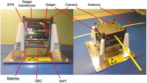
Finally the three other payloads onboard 3Cat-1, MEMS monoatomic-oxygen detector, wireless power transfer and graphene transistor, are attractive experiments to be tested in space environment. However, it would have been much more difficult to test them in real space environment unless a platform like a nano-satellite is provided, what represents another demonstration of the capabilities that this small technology offers. 3Cat-1 is under its final integration process (see ), and it will be integrated in the orbital deployer next 6 April 2016. Its launch is foreseen for May 2016, if there are no additional delays.
Figure 13. 3Cat-1 mechanical integration.
Following 3Cat-1, 3Cat-2 “6U” CubeSat with a Global Navigation Satellite System-Reflectometry (GNSS-R) experiment is being launched on Summer 2016 (Camps et al. Citation2014).
Disclosure statement
No potential conflict of interest was reported by the authors.
Additional information
Funding
References
- Araguz, C. (2014). Towards a modular nano-satellite platform: Prolog constraint-based scheduling and system architecture ( MSc thesis). Technical University of Catalonia.
- Beaumet, G., G. Verfaillie, and M. C. Charmeau. (2011). Feasibility of autonomous decision making on board an agile earth-observing satellite. Computational Intelligence, 27, 125–136. doi:10.1111/j.1467-8640.2010.00375.x
- Bohan, J. E., Jr. Low voltage driven oscillator circuit. (1988). US Patent 4,734,658.
- Bou-Balust, E., A. P. Hu, and E. Alarcon. (2015, October). Scalability analysis of SIMO non-radiative resonant wireless power transfer systems based on circuit models. IEEE Transactions on Circuits and Systems I, 62(10), 2574–2583. doi:10.1109/TCSI.2015.2469015
- Bragós, R., A. Camps, and A. Oliveras. (2012). Design of the advanced engineering project course of the third year of electrical engineering at telecom BCN. Proceedings of the 8th International CDIO Conference, CDIO Office, Brisbane.
- California Polytechnic State University. (2009). CubeSat design specification. Technical report. Retrieved from http://www.cubesat.org/images/developers/cds_rev12.pdf.
- Camps, A., R. Jove-Casulleras, A. Alonso-Arroyo, R. Olive, A. Amezaga, D. Vidal, and J. F. Munoz, (2014). The 3Cat-2 project: GNSS-R in-orbit demonstrator for earth observation hugo Carreno-Luengo. 4S Small Satellites Systems and Services Symposium, 4S 2014 Secretariat, ESA Conference Bureau, Mallorca.
- Chien S., Sherwood R., Tran D., Cichy B., Rabideau G., Castano R. et al. (2005). Using autonomy flight software to improve science return on earth observing one. Journal of Aerospace Computing, Information, and Communication, 2, 196–216. doi:10.2514/1.12923
- Chien S., Doubleday J., Thompson D., Wagstaff K., Bellardo J., Francis C., et al. (2014). Onboard autonomy on the Intelligent Payload EXperiment (IPEX) Cubesat mission: A pathfinder for the proposed HyspIRI mission intelligent payload module. Proc 12th International Symposium in Artificial Intelligence, Robotics and Automation in Space, ESA Conference Bureau, Montreal.
- de Novaes Kucinskis, F., and M. G. V. Ferreira. (2013). On-board satellite software architecture for the goal-based Brazilian mission operations. Aerospace and Electronic Systems Magazine, IEEE, 28, 32–45. doi:10.1109/MAES.2013.6575409
- Heynderickx, D., B. Quaghebeur, E. Speelman, and E. Daly. (January 2000). ESA’s Space Environment Information System (SPENVIS) - A WWW interface to models of the space environment and its effects. In 38th Aerospace Sciences Meeting and Exhibit, Reston: American Institute of Aeronautics and Astronautics. DOI: 10.2514/6.2000-371.
- Iacopino, C., and P. Palmer. (2013). “Autonomy.” Distributed space missions for earth system monitoring. New York: Springer. 309–329. doi:10.1007/978-1-4614-4541-8
- Iannazzo, M., Lo Muzzo, V., Rodriguez, S., Rusu, A., Lemme, M., & Alarcón, E. (2015). “Design exploration of graphene-fet based ring-oscillator circuits: a test-bench for large-signal compact models”. IEEE International Symposium on Circuits and Systems 2015. doi:10.1109/ISCAS.2015.7169247
- Jove Casulleras, R. (2015, February). Contribution to the development of pico-satellites for Earth observation and technology demonstrators ( PhD Thesis). Universitat Politecnica de Catalunya BarcelonaTech. Retrieved from http://hdl.handle.net/10803/286237
- Jove-Casulleras, R., J. Ramos, H. Ccorimanya, A. Camps, A. Amezaga, E. Alarcon, and E. Bou. (2014, May). Temperature gradient sensor from pulsed power supply duty cycle in ultra-low-power energy harvesting system. Electronics Letters, 50(11), 826–828. ISSN 0013-5194. doi:10.1049/el.2014.0399.
- Leger, L. (1983). Oxygen atom reaction with shuttle materials at orbital altitudes - Data and experiment status. In American Institute of Aeronautics and Astronautics, Aerospace Sciences Meeting; 21st January 10–13, 1983, NASA, American Institute of Aeronautics and Astronautics. https://ntrs.nasa.gov/search.jsp?R=19830035285
- Maine, S. G. (2010). Implementació d’oscil.ladors digitals polsats ( Master’s thesis) Escola Tecnica Superior d’Enginyeria de Telecomunicacions de Barcelona, Universitat Politecnica de Catalunya.
- Ralph R. R., (2014). Spacecraft polymers atomic oxygen durability handbook. Technical report. NASA, NASA-HDBK-6024. https://standards.nasa.gov/file/489/download?token=zkg8F8pQ
- Ortega, P., R. Jove-Casulleras, A. Pedret, R. Gonzalvez, G. Lopez, I. Mart ́ın, M. Domínguez, R. Alcubilla, and A. Camps. (2013). An IBC solar cell for the UPCSat-1 mission. Proceedings of the 9th Spanish Conference on Electron Devices, Valladolid: CDE. February 12–14, 2013. doi:10.1109/CDE.2013.6481410
- Porter, A. K., D. J. Alinger, R. J. Sedwick, J. Merk, R. A. Opperman, A. Buck, G. Eslinger, P. Fisher, D. W. Miller, and E. Bou. (2014, September). Demonstration of electromagnetic formation flight and wireless power transfer. AIAA Journal of Spacecraft and Rockets, 51(6), 1914–1923. doi:10.2514/1.A32940
- Ricart, J., J. Pons-Nin, E. Blokhina, S. Gorreta, J. Hernando, T. Manzaneque, J. L. Sanchez-Rojas, O. Feely, and M. Dominguez. (2010, August). Control of MEMS vibration modes with pulsed digital oscillators—Part II: Simulation and experimental results. IEEE Transactions on Circuits and Systems I: Regular Papers, 57(8), 1879–1890. ISSN 1549-8328. doi:10.1109/TCSI.2009.2038543
- Sinclair, D., and J. Dyer. (2013 1–12). Radiation effects and COTS parts in small sats. 27th Annual AIAA/USU Conference on Small Satellites. http://digitalcommons.usu.edu/smallsat/2013/all2013/69/.
- Wojtkowiak, H., O. Balagurin, G. Fellinger, and H. Kayal. (2013). ASAP: Autonomy through on-board planning. 6th International Conference on Recent Advances in Space Technologies (RAST), pp.377–381. DOI: 10.1109/RAST.2013.6581235