 ?Mathematical formulae have been encoded as MathML and are displayed in this HTML version using MathJax in order to improve their display. Uncheck the box to turn MathJax off. This feature requires Javascript. Click on a formula to zoom.
Abstract
In this paper, we investigate numerically the dynamic pulsation nature of stresses acting on hopper walls during filling and discharging granular materials from silos. From the results, at the end of filling process, it can be concluded that the larger the frictional wall coefficient is, the less the ultimate stress values acting on the hopper wall will be. Furthermore, for smaller values of internal friction, a consistent stress fluctuation appears for a slightly long period of time before the stress trace turns to a straight line. For the discharging process, the required time for the discharging of the silo is almost the same for different values of wall frictions. Moreover, for large values of internal friction coefficients, the discharging process takes more time.
Public Interest Statement
The silo system has been considered as one of the emerging issues in the granular materials research over many years. It is known that granular materials cannot be characterized as gas and fluid or solid. Discrete element methods (DEM’s) are numerical techniques capable of simulating the entire behavior of systems of discrete interacting elements. In the present paper, by using this numerical simulation technique, we study the effects of the friction between the particles themselves and between the particles and the boundary walls in a silo system during filling and discharging processes. It is found that, for large values of friction between the particles’ system, the discharging process takes more time. Moreover, the required time for the discharging of the silo is almost the same for different values of particle/wall frictions.
1. Introduction
The silo system has been considered as one of the emerging issues in the granular materials research over many years. Past and current research efforts focus on investigating many aspects relevant to the silo system. Problems in silo, such as flow blockage, jamming, segregation, dead zones, and silo collapse attract the interest of researchers and raise the importance to study the storage vessels. Great efforts have been made to closely study aspects such as flow pattern of granular material through silos, stress field propagation along silo walls, force fluctuation at the boundary of granular flow in silo, and the effect of particle shape on silo discharge.
Recently, many experimental methods have been conducted in the analysis of wall stress measurements. For instance, Chou, Tzeng, Smid, Kuo, and Hsiau (Citation2000) investigated the pressure of moving granular bed acting on the side walls. Force fluctuation at the boundary of a two-dimensional granular flow was investigated by Longhi, Easwar, and Menon (Citation2002). Simultaneous measurements of both the flow pattern and wall pressure in a full scale silo storing granular solids were conducted by Chen, Rotter, Ooi, and Zhong (Citation2006).
Extensive discrete approaches in two and three dimensions have been conducted to investigate problems relevant to silo operation. Many aspects such as filling and discharging under gravity of non-cohesive discs in two and three dimensions from silos have been carried out via discrete element Newtonian dynamics simulations (Langston, Tüzün, et al., Citation1995). Pressure and shear forces that acting on the wall of an out-flowing hopper using discrete element simulations has been measured (Ristow & Herrmann, Citation1995). Depending on various material and geometrical parameters, the discharge process has been investigated in two-dimensional hopper on various material and geometrical parameters (Cleary & Sawley, Citation2002). It was shown that the outflow rate does not depend on the restitution coefficient and the transition from funnel flow to mass flow behavior is clearly observed when the hopper angle increases. Discrete element method supported by an averaging method has been employed to quantitatively investigate the velocity and stress distribution of a hopper flow (Zhu & Yu, Citation2003). Their results indicate that the discrete element technique is a powerful tool for macroscopic analysis of the dynamic behavior of hopper flow. By using large-scale discrete element computer simulations, the change of the vertical stress profiles with dimensionality has been investigated by Landry, Grest, et al. (Citation2004). A general method was proposed by Ristow (Citation1997) for performing discrete element simulations of huge system of particles through partitioning them into sub-domains that are analyzed separately. The effect of wide selection of particle shapes on hopper discharging has been investigated in many attempts. It was shown that the circular particles have little resistance and shear forces such results are due to Masson and Martinez (Citation2000). Further attempts that concern with the effect of particle mechanical properties on filling and discharging granular materials from silos have been conducted (Goda & Ebert, Citation2005; Yang & Hsiau, Citation2001). More and more attempts have been directed toward studying the behavior of granular flow during filling and discharging granular materials from silos (Hirshfeld & Rapaport, Citation2001; Nguyen, Cogné, Guessasma, Bellenger, & Fortin, Citation2009; Parisi, Masson, & Martinez, Citation2004; Sykut, Molenda, & Horabik, Citation2008). In the present work, we establish a discrete element model and numerical algorithm to investigate the pulsation profiles of stresses acting on hopper walls during filling and discharging granular materials from silos. In order to determine the points at which the stress pulsation exhibits more vacillations, different values of coefficients for both wall and internal frictions are considered to study the influences of these parameters on the stress pulsation nature during the processes of filling and discharging.
2. Implementation of DEM model
The present numerical simulations are based on the soft-particle discrete method which originally was proposed by Cundall and Strack (Citation1979). In our simulation model, the granular particles are subjected, during simulation, to two types of forces including contact forces and gravitational force. Unlike the gravitational body force, the particle contact forces act only when the particle is in contact with other particles and/or with a boundary wall. The normal contact force is determined by a damped linear spring model, while the tangential contact force is determined by a linear spring in series with a frictional sliding element model. The interaction forces developed between two particles or between particle and boundary wall are calculated based on the physical properties and the relative velocities. The dynamic equations for the motion for each of the particles under these forces are(1)
(1)
(2)
(2)
where mi, Ii, , and
are, respectively, the mass, rotational moment of inertia, position, and rotational vectors of the centre of particle i,
,
and
are, respectively, gravitational body force and contact forces acting on particle i due to particle j and boundary wall wk, Np and Nw are, respectively, the number of particles and walls in the simulation. For simplicity, we denote
(3)
(3)
(4)
(4)
Therefore, Equations (1 and 2) become(5)
(5)
(6)
(6)
Unlike the gravitational body force, the particle contact forces act only when the particle is in contact with other particles and/or with a boundary wall. In the analysis of the system, any contact force is decomposed into normal and tangential components. For any typical pair of particles i and j, if they are in contact, then the contact force is determined by the following formula(7)
(7)
where and
are unit vectors in the normal and shear directions of the contact plane,
and
are, respectively, the magnitudes of the normal contact force and shear contact force, namely,
(8)
(8)
(9)
(9)
where and
are, respectively, the particle-particle normal and tangential spring coefficients,
and
are, respectively, the elastic contribution of the contact force between the particles i and j in the normal direction (
direction) and the friction coefficient of the granular particles,
and
are, respectively, the normal compression and the tangential displacement between the particles and over the time step Δt = t – t0, Ri and Rj are the radii of the particles i and j. In order to reduce the number of contact checks for each particle, a neighboring cell technique is implemented in the present simulations. Once all forces and moments acting on particle due to contacts are identified, new velocities and positions of all particles are computed by numerical integration of Newton’s equation of motion. Setting
(10)
(10)
Therefore, ∀i = 1, 2, 3, …, Np, we have a system of first-order ordinary differential equations as follows(11)
(11)
(12)
(12)
(13)
(13)
(14)
(14)
Thus, setting
yields a system of 4Np first-order ordinary differential equations that represents the dynamic equations for the motion of the Np particles and can be expressed by(15)
(15)
(16)
(16)
By using the central difference scheme and considering that ,
,
,
,
, and
are all constants over the time interval
, (16) becomes
(17)
(17)
Over , further application of the central difference scheme to (15) at time
yields,
(18)
(18)
Substituting (17) into (18), one can obtain new translational and rotational displacements at time t = N + 1 as follows(19)
(19)
The new translational and rotational velocities and
, at time t = N + 1, can be determined by,
(20)
(20)
In order to reduce the number of contact checks for each particle, neighboring cell technique is implemented in the present simulations. Once the particle contact forces are calculated, the new velocity and position can be obtained by integrating the differential equations for particle motion over small simulation time step. The input parameters in our simulations include: physical properties of the granular particles under consideration, initial conditions, and boundary conditions. The initial conditions include: the initial positions and velocities of all particles and the geometry of the boundary conditions. All parameters are non-dimensionalized using the density of particle, gravitational acceleration, and particle diameter. A list of used mechanical and environmental dimensionless simulation parameters are given in Table .
Table 1. Baseline parameters used in the simulation
3. Model setup and simulation schemes
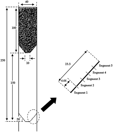
The silo system under consideration consists of two connected silos one above the other as shown in Figure . To simulate the real silo filling process, the particles are modeled as a conglomeration of discs with a uniform distribution of diameters, 0.81 ≤ d ≤ 0.99 mm. The discs dispersed inside the upper silo, with given random initial positions and velocities, and are allowed to fall under gravity down into the upper silo. During the filling process, the outlet of the upper silo is kept closed. Hence, due to damping forces, the particles ultimately come to rest at the bottom of the silo. Once the upper silo is almost filled with particles and the system has achieved a nearly steady-state condition, the outlet of the upper silo is opened and the particles start to flow out of the silo under gravity toward the lower silo. To study the nature of normal stresses exerted on the hopper wall of the lower silo, we divide the hopper wall into five equidistance segments as shown in Figure . The segment length is approximately five times the particle diameter.
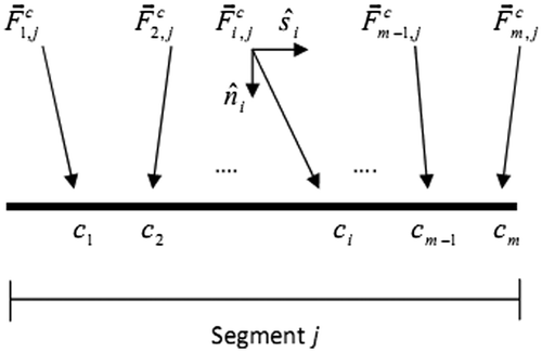
During typical simulation, each segment element of the hopper’s wall bears stresses that are exerted by the granular material. To analyze these stresses, we suppose that segment j (where 1 ≤ j ≤ 5) has m contact points c1, c2, ..., cm as shown in Figure .
Then the corresponding contact forces acting on segment j are(21)
(21)
We define the average contact force, , acting on segment j(with length
) due to the m contact points by
(22)
(22)
such that
and(23)
(23)
are, respectively, the normal and tangential components of and
represents normal and tangential unit vectors corresponding to the segment j at the contact points. Therefore, the total stresses acting on segment j, namely,
can be obtained by
(24)
(24)
where and
are, respectively, the gravity force acting on segment j in the x and y directions.
4. Flow pattern and velocity field
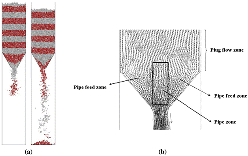
Once the outlet of the upper hopper is opened, the particles start to flow out of the silo under gravity toward the lower silo. The flow pattern and the velocity field of the granular material at different simulation time steps are shown in Figure . Mass flow can be observed to occur in the entire upper silo. At the point of transition where the silo wall meet the hopper wall, the particle moving direction changes sharply from straight down to a direction parallel to the hopper inclined wall. Consequently, during the discharging process, the stress on the hopper wall reaches the maximum at these two points and decreases toward the outlet. Hence, we expect that the value of the acting stress on segment five of the hopper wall to be the maximum. However, it has been observed that the more particles reach the point close to the outlet the more they gain room to move. Thus, the stress profile of segment one may more likely show an oscillating nature than other segments of the hopper’s wall.
Figure 3. Snapshots for various simulation time instants showing the flow pattern and the velocity field of granular material.
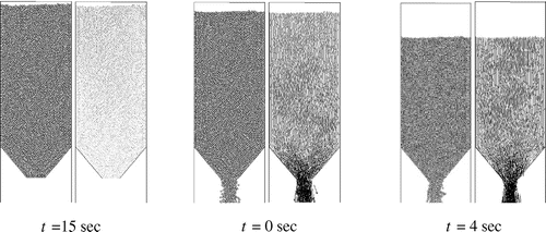
Even though mass flow can be seen to occur in the entire silo as can be seen in Figure (a), it is possible to recognize different zones with different flow patterns. These flow zones can be divided into: pipe, pipe feed, and plug flow zones. Figure (b) shows the three different flow zones.
5. Simulation results and discussion
In this section, we investigate the stress fluctuating nature developed along the hopper wall during filling and discharging of a silo. A simulated filling and discharging processes were carried out to study the variation in the stress that acts on the hopper wall, with time. Moreover, we investigate the dynamic nature of these stresses at various values of the wall and the internal friction coefficients.
5.1. Stress pulsation mechanism
We, partially, filled both the upper and the lower silos by allowing particles, having random initial positions and velocities, to fall down under gravity. The upper silo was filled with 2,500 particles while 4,500 particles were placed in the lower silo. Then the outlet of the upper silo was opened and the particles start to flow down from the upper silo under gravity toward the lower silo. Snapshots of the process at different time steps are shown in Figure .
Figure 5. Simulation snapshots showing the discharging of granules at various simulation time instants.
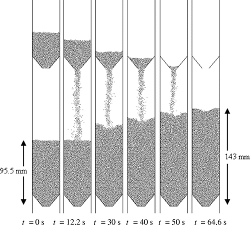
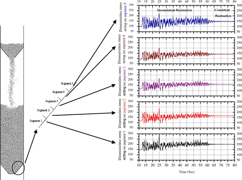
At t = 0, each of the five segments of the lower silo wall, bears an initial stress value due to the initial existing particles in the lower silo. The particle packing plays an important role on the initial stress profile on these segments. Once the particles that flow out from the upper silo strike the static surface of the granular material in the lower silo, the stress value acting on each segment starts to increase. Figure shows the stress profile acting on each segment of the hopper’s wall of the lower silo throughout the simulation time.
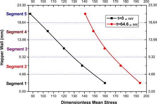
At t ≅ 12.2 s, particles from the upper silo started to hit the static surface of granular material in the lower silo. Consequently, stress trace of each segment starts to fluctuate as the height of bulk material in the lower silo starts to increase. For each stress’s profile, two fluctuation traces can be identified, namely, inconsistent and consistent stress fluctuation traces. The inconsistent stress trace dominates as long as there are particles falling down from the upper silo and hitting the granular surface in the lower silo. As shown in Figure , it extends from t ≅ 12.2 – 64.6 s. Once all the particles of the upper silo reach the lower silo and settle down, the stress trace on each segment does not turn to a straight line directly. A temporary consistent fluctuation which has a harmonic motion-like trace starts to dominate before the stress profile turns to a straight line. Therefore, the system possesses a temporary dynamic pulsation stress-like nature on the hopper wall after it appears to reach a near static state. The stress profile on segment five which is the closest to the surface of bulk material appears to have larger trace fluctuation amplitude than that on other segments of the hopper wall during the process. Figure shows the dimensionless mean stress acting on the hopper wall of the lower silo at two different simulation stages, namely, at t = 0 s and t = 64.6 s. It is obvious that the stress value on each segment increases and almost on all segments the stress increases monotonically throughout the simulation time. In both cases, the stress acting on segment one appears to be the largest and the wall stress decreases gradually along the hopper wall toward segment five. This result is, generally, in agreement with existing experiment results (Cleary & Sawley, Citation2002; Goda & Ebert, Citation2005; Masson & Martinez, Citation2000).
5.2. Influence of wall friction
In this section, we investigate the effect of the wall friction on the dynamic nature of the wall stress developed during filling and discharging of the lower silo. A sequence of test simulations was carried out. In each simulation, we vary the value of the wall frictional coefficient µpw and maintain other simulation parameters the same. The experiments were conducted using the parameter values shown in Table , except for the value of µpw which varies from 0.1 to 0.9. The methodology was to, completely, fill the upper silo with 7,000 particles and let them to settle down till they come to rest. Then the outlet was opened and the particles flow down under the gravitational force into the lower silo. The stresses acting on each segment of the hopper’s wall, during filling the lower silo for various values of µpw, are shown in Figure .
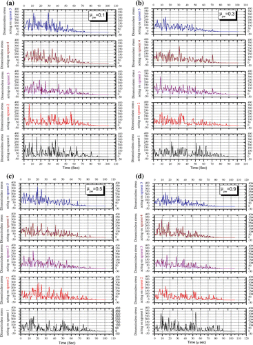
Figure 8. Variations of stresses acting on the hopper’s wall during filling (a) μpw = 0.1, (b) μpw = 0.3, (c) μpw = 0.5, (d) μpw = 0.9.
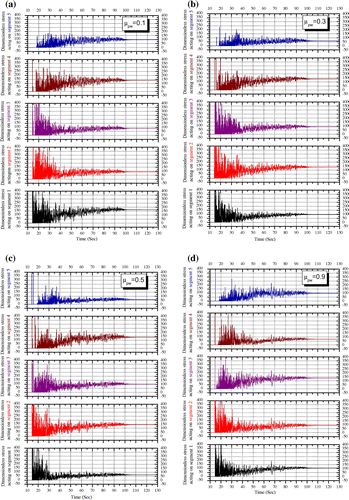
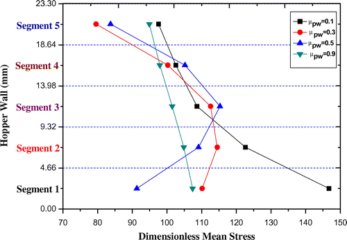
Our results reveal that, after the filling process, granular systems with small wall fictional coefficients, in general, achieve static state faster than those with large values. For the cases of µpw = 0.1 and 0.3, there are no stress fluctuation after t = 100 s which means that the two systems are stable and there is no stress variation after this time. However, the stress fluctuation continues after t = 100 s for the cases of and µpw = 0.5 and µpw = 0.9, which means that there is still a stress variation occurring beyond this time. Nevertheless, the amplitude of the stress fluctuation tends to be smaller as the wall frictional coefficient increases. This is because of the rapid dissipation of the kinetic energy of particles in direct contact with the hopper wall with high friction. At the end of the filling process, in general, we observe that the ultimate stress values acting on each segment decrease as the value of µpw increases. This can be explained by the mechanism that the larger is µpw, the more percentage of material weight the silo walls will carry. Figure shows the mean stress acting on each segment of the hopper wall in the lower silo at the end of the filling process. Except the case when μpw = 0.5, stresses exerted on segment one were the maximum while those exerted on segment five were the minimum. However, no considerable changes were observed on the stresses that acting on other segments.
Figure 9. Mean stress acting on hopper’s wall at the end of filling process for μpw = 0.1, μpw = 0.3, μpw = 0.5, and μpw = 0.9.
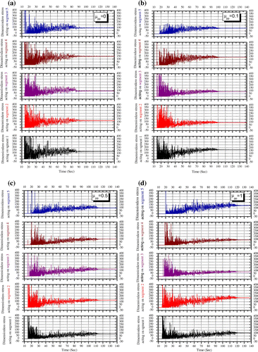
To investigate the influence of µpw on the discharging process, another series of simulations was performed for discharging the particles from the lower silo this time. In these simulations, we also use the mechanical and environmental parameter values listed in Table . Different values of µpw were considered in each simulation, namely, 0.1, 0.3, 0.5, and 0.9. During the process, the stresses acting on the hopper’s segments were measured. At t = 0 s, the lower silo outlet opened and the particles started to flow out of the silo under gravity. As the particles flow out form the silo, the values of the stresses acting on each segment start to fluctuate and decrease gradually till the end of the discharging process. Figure shows the stress traces for each segment along the hopper’s wall of the lower silo during the discharging process. Each graph corresponds to a different value of µpw while other simulation parameters are kept the same. The results show that, for different values of µpw, the required time for the discharging of the silo is almost the same. Moreover, the fluctuation amplitude of the stress that acting on segment five is larger than that acting on the other segments. In general, the graph shows that the stress fluctuation amplitude decreases as the value of µpw increases.
Figure 10. Variations of stresses acting on the hopper’s wall during discharging for (a) μpw = 0.1, (b) μpw = 0.3, (c) μpw = 0.5, (d) μpw = 0.9.
According to our simulation outputs, the stress fluctuation profile, during the discharging process, is not considerably affected by the value of µpw. However, in general, the fluctuation amplitude for larger values of µpw tends to be smaller than that for small values of µpw. On segment five the stress fluctuation trace has the largest amplitude compared to those on all the other segments. Therefore, the points of transition from vertical silo wall to the hopper wall bear the maximum value of the acting stresses during the discharging process.
5.3. Influence of internal friction
To investigate the effect of the internal friction coefficient µpp on the stresses profile, we follow the same procedure as that in 5.2. We run a series of simulations in which all simulation parameters are fixed while µpp is given different values each time. We consider four different values of µpp, namely, 0, 0.1, 0.5, and 1. For the filling process, the outlet of the filled upper silo was opened and the particles started to fall down into the lower silo. Figure shows the resulting stresses profiles on the segments of the hopper’s wall for the four different values of µpp. Results show that granular systems with small values of µpp comes to rest faster than those with large values of µpp. Moreover, at the end of the filling process and when the assembly eventually comes to rest at the base of the lower silo, stress profiles appear to have different traces. For the case of µpp, a consistent stress fluctuation that has a simple harmonic motion-like trace appears for a slightly long period of time before the stress trace turns to a straight line. On the other hand, for other cases i.e. µpp = 0.1, 0.5, and 1, no long consistent stress fluctuation has been observed and the stress trace turns to a straight line rapidly. This phenomenon can be explained as flows, for µpp = 0, there is no internal friction between particles and the system has a fluid-like properties. In this case particles take more time to settle down and achieve a real steady state. Another observation, that can be obtained from Figure , is that the stress fluctuation amplitude for the systems with smaller value of µpp is greater than that for the systems with larger values of µpp. This is reasonable for the same reason that has been mentioned earlier.
Figure 11. Variations of stresses acting on hopper’s wall during filling for (a) μpp = 0, (b) μpp = 0.1, (c) μpp = 0.5, (d) μpp = 1.
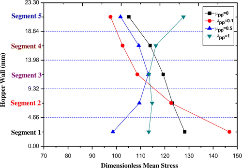
At the end of the filling process, the mean stress acting on each segment is plotted in Figure . For µpp = 0, the ultimate stress profile is reasonably close to a straight line as the bulk material has a fluid-like property. It is also found that at the end of filling process, for , stresses exerted on segment five were the maximum while those exerted on segment one were the minimum. In these cases, the transition’s points of the silo system carry most of the load of the bulk material due to the large internal friction coefficients. Conversely, segment 1 bears the maximum stress for
due to the low internal friction between particles.
Figure 12. Mean stress acting on hopper wall at the end of filling process for μpp = 0, μpp = 0.1, μpp = 0.5, and μpp = 1.
For the effect of the internal friction coefficient µpp on the stresses during the discharging process, we performed a series of simulations using the same four different values of µpp. Other parameters were preserved the same. Figure shows the stresses profile developed on each segment of the hopper’s wall during discharging of the lower silo for the four different values of µpp.
Figure 13. Variations of stresses acting on hopper’s wall during discharging (a) μpp = 0, (b) μpp = 0.1, (c) μpp = 0.5, and (d) μpp = 1.
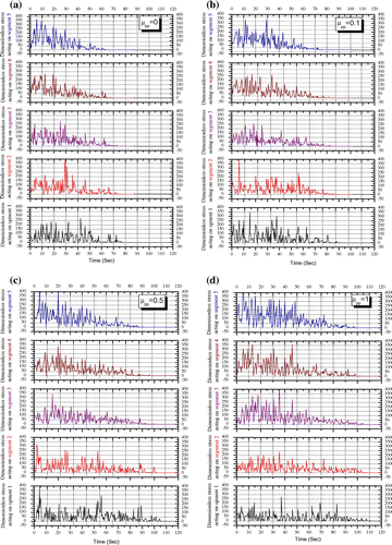
According to our results, the discharging process takes more time for large values of µpp as would be expected. Moreover, due to dilation of the particles at the outlet zone of the silo system during flow, segment one almost maintains the same fluctuation amplitude throughout the discharging process. For other segments, the fluctuation stress trace gradually decreases till it turns to a straight line at the end of the process. On the transition between the hopper wall and the vertical bin wall (segment 5), the stress appears to have the maximum fluctuation.
6. Concluding remarks
Two-dimensional soft particle discrete element simulations have been conducted to simulate the filling and discharging of granular particles from a silo system. The simulated filling and discharging processes have been carried out to study the variation in stress, which acts on the hopper wall, with time. The effects of wall and internal friction coefficients on the dynamic nature of stresses acting on hopper wall have also been investigated. From the results, it can be concluded that the stresses that act on the hopper wall have a temporary dynamic pulsation-like nature at the end of the filling process when the granular particles appear to reach a near static state. Accordingly, under the condition that the particle-wall contact force, in the normal direction, is modeled as visco-elastic (damped harmonic oscillator), the proposed soft particle discrete element model is capable of simulating the silo system. The influences of wall and internal friction coefficients on the oscillating nature have been investigated during filling and discharging processes. At the end of filling process, it can be concluded that the larger the µpw is, the less the ultimate stress values acting on the hopper wall will be. Moreover, for smaller values of µpp, the system has fluid-like properties and hence, the particles take more time to settle down and achieve a real steady state. Therefore, a consistent stress fluctuation appears for a slightly long period of time before the stress trace turns to a straight line. For the discharging process, the results show that for different values of µpw, the required time for the discharging of the silo is almost the same. Furthermore, the fluctuation amplitude of stress acting on the upper part of the hopper wall is larger than that on the other parts. Also, it is found that the discharging process takes more time for large values of µpp. Due to the particles’ dilation at the zone of the silo’s outlet, the lower part of the hopper wall maintains almost the same fluctuation amplitude throughout the discharging process. On the transition between vertical bin and hopper’s wall, the stress appears to have the maximum fluctuation during the discharging process for all different values of μpp.
Additional information
Funding
Notes on contributors
Waseem Ghazi Alshanti
Waseem Ghazi Alshanti received the PhD degree in numerical analysis from the Department of Mathematics and Statistics, Curtin University, Australia, in 2010 where he worked as a lecturer from 2007 to 2010. Based on his excellent results he achieved in his PhD studies, he was awarded Curtin University completion scholarship as well as the mathematics honours and postgrad prize. Currently, he is working as Assistant Professor of Mathematics at the University of Hail. His research interests and areas of expertise include: Applied mathematical modeling (Fluid dynamics, granular flow, geomechanics theory, continmuum mechanics theory), Image processing, Difference equations, and advanced real analysis.
References
- Chen, J. F., Rotter, J. M., Ooi, J. Y., & Zhong, Z. (2006). Correlation between flow pattern and wall pressures in a full scale silo. Engineering Structures, V29, 2308–2320.
- Chou, C. S., Tzeng, C.Y., Smid, J., Kuo, J. T., & Hsiau, S. S. 21–24, (2000, May). Experimental study of moving granular bed: Wall stress measurement.14th ASCE Engineering Mechanics Division Conference, Austin, TX.
- Cleary, P. W., & Sawley, M. L. (2002). DEM modelling of industrial granular flows: 3D case studies and the effect of particle shape on hopper discharge. Applied Mathematical Modelling, 26, 89–111. 10.1016/S0307-904X(01)00050-6
- Cundall, P. A., & Strack, O. D. L. (1979). A discrete numerical model for granular assemblies. Géotechnique, 29, 47–65.10.1680/geot.1979.29.1.47
- Goda, T. J., & Ebert, F. (2005). Three-dimensional discrete element simulations in hoppers and silos. Powder Technology, 158, 58–68. 10.1016/j.powtec.2005.04.019
- Hirshfeld, D., & Rapaport, D. C. (2001). Granular flow from a silo: Discrete-particle simulations in three dimensions. The European Physical Journal E, 4, 193–199.10.1007/s101890170128
- Landry, J. W., Grest, G. S., et al. (2004). Discrete element simulations of stress distributions in silos: Crossover from two to three dimensions. Powder Technology, 139, 233–239.10.1016/j.powtec.2003.10.016
- Langston, P. A., Tüzün, U., et al. (1995). Discrete element simulation of granular flow in 2D and 3D hoppers: Dependence of discharge rate and wall stress on particle interactions. Chemical Engineering Science, 50, 967–987.10.1016/0009-2509(94)00467-6
- Longhi, E., Easwar, N., & Menon, N. (2002). Large force fluctuations in a flowing granular medium. Physical Review Letters, 89, 045501.10.1103/PhysRevLett.89.045501
- Masson, S., & Martinez, J. (2000). Effect of particle mechanical properties on silo flow and stresses from distinct element simulations. Powder Technology, 109, 164–178.10.1016/S0032-5910(99)00234-X
- Nguyen, V. D., Cogné, C., Guessasma, M., Bellenger, E., & Fortin, J. (2009). Discrete modeling of granular flow with thermal transfer: Application to the discharge of silos. Applied Thermal Engineering, 29, 1846–1853.10.1016/j.applthermaleng.2008.09.009
- Parisi, D. R., Masson, S., & Martinez, J. (2004). Partitioned distinct element method simulation of granular flow within industrial silos. Journal of Engineering Mechanics, 130, 71–779.
- Ristow, G. H. (1997). Outflow rate and wall stress for two-dimensional hoppers. Physica A: Statistical Mechanics and its Applications, 235, 319–326.10.1016/S0378-4371(96)00365-2
- Ristow, G. H., & Herrmann, H. J. (1995). Forces on the walls and stagnation zones in a hopper filled with granular material. Physica A: Statistical Mechanics and its Applications, 213, 474–481.10.1016/0378-4371(94)00249-S
- Sykut, J., Molenda, M., & Horabik, J. (2008). DEM simulation of the packing structure and wall load in a 2-dimensional silo. Granular Matter, 10, 273–278.10.1007/s10035-008-0089-z
- Yang, S. C., & Hsiau, S. S. (2001). The simulation and experimental study of granular materials discharged from a silo with the placement of inserts. Powder Technology, 120, 244–255.10.1016/S0032-5910(01)00277-7
- Zhu, H., & Yu, A. (2003). A numerical study of the stress distribution in hopper flow. China Particuology, 1, 57–63.10.1016/S1672-2515(07)60109-2

