 ?Mathematical formulae have been encoded as MathML and are displayed in this HTML version using MathJax in order to improve their display. Uncheck the box to turn MathJax off. This feature requires Javascript. Click on a formula to zoom.
Abstract
Soft compliant grasping is essential in delicate manipulation tasks typically required in manufacturing and/or medical applications to prevent stress concentration at the point of contact. In comparison with their rigid counterparts, the intrinsic compliance of soft grippers offers simpler control and planning of the grasping action, especially where robots are faced with a number of objects varying in shape and size. However, quantitative analysis is rarely utilized in the design and fabrication of soft grippers, due to the fact that significant and complex deformation occurs once the soft gripper is in contact with external objects. In this paper, we demonstrate the design of a soft gripper using our novel bimorph-like pneumatic bending actuators. The gripper was modelled through finite element analysis to reflect its gripping capability during interaction with certain targeted objects. The proposed systematic design and analytical model was validated via experiments. The system’s gripping capability was evaluated with objects of different weight and dimension. In addition, compliance testing has proved that the proposed soft gripper is able to grip objects of 60 g from the side, without causing exceeding concentration stress on the targeted object.
Public Interest Statement
Soft compliant grasping is often essential in delicate manipulation tasks typically required in manufacturing and/or medical applications to prevent stress concentration at the point of contact and avoid damage to the delicate surface of the object being grasped. In comparison with their rigid counterparts, the intrinsic compliance of soft grippers offers simpler control and planning of the grasping action, especially where robots are faced with a number of objects varying in shape and size. Here, we demonstrate the design of a soft gripper using our novel bimorph-like pneumatic bending actuators. This actuator deviates from the currently available pneumatic bending actuators as it does not bulge radially when pressurised. The amount of bending and grasping force can be controlled by the physical dimensions of the actuator.
1. Introduction
Autonomous gripping has a wide range of applications in industrial, medical and in-home service fields. Grippers designed around fluidic bending actuators (FBA), which are normally in the form of hyper-elastic synthetic films powered by pressurized fluids (pneumatics or hydraulics), are increasingly gaining attention in pick-and-place applications due to their remarkable characteristics, such as electro-mechanical and chemical stability, excellent conformability and flexibility, light weight, low cost and safety for operation in unstructured situations (Michäel & Dominiek, Citation2010; Trivedi, Rahn, Kier, & Walker, Citation2008). They have the ability to provide stable multi-point grasp, substantially reducing the efforts required for accurate modeling, mechanical design, sensing and complex planning of the grasping action, which are usually demanded in rigid-structured counterparts (Bauer et al., Citation2014; Howard & Bekey, Citation2000; Robot Manipulation of Deformable Objects, Citation2000). Their excellent adaptability over varying shapes also effectively increases the safety of both the environment and the actuator itself (Yoel, Alon, & Kosa, Citation2011). As opposed to electric-powered soft grippers, FBA-based grippers avoid the use of high electric fields, and there are no major constraints to maintain the FBA at a given deflected position for an arbitrary time (Trivedi et al., Citation2008). Although a cumbersome power source may act as a constraint factor limiting the miniaturization of FBA-based systems, pioneering works have been carried out on the development of various miniature air sources for portable and wearable soft robotic devices (Michael et al., Citation2014). These inherent properties of FBA are mainly dictated by the structure and materials used in design, where typical techniques include asymmetrical profiles (Gorissen, De Volder, De Greef, & Reynaerts, Citation2011; Gorissen, Donose, Reynaerts, & De Volder, Citation2011; Gorissen, Vincentie, Al-Bender, & Reynaerts, Citation2013; Hirai, Masui, & Kawamura, Citation2001; Konishi et al., Citation2006; Suzumori, Iikura, & Tanaka, Citation1991) and/or asymmetrical materials (Che-Ming, John, Manu, Carlo, & Parameswaran, Citation2011; Onal & Rus, Citation2012), multi-chamber architectures (Kadowaki, Noritsugu, Takaiwa, Sasaki, & Kato, Citation2011; Koichi, Shuichi, Kenta, & Kazuhiro, Citation2013; Martinez et al., Citation2013; Suzumori, Wakimoto, Miyoshi, & Iwata, Citation2013) and hybrid designs combining actuators of different working principle (Yang & Chen, Citation2016). However, in most of the existing examples, the gripping capability when interacting with objects are not truly reflected through a systematic quantitative analysis. Instead, empirical data and/or mathematical modelling without loading are used to justify the viability of design. Such methods may become unreliable especially when unpredictable and random deformation occurs once a soft actuator is in contact with unknown and varying objects. Since soft robotic grippers have limited control capabilities, a more systematic and thorough design process is needed before fabrication to ensure they have the desired capabilities to perform complex and varying manipulation tasks.
In this paper, a soft robotic gripper was developed by using a previously designed fiber-reinforced bimorph pneumatic bending actuator (PBA) specified in (Boran, Aw, Morteza, & McDaid, Citation2016). A systematic finite element analysis (FEA) was performed to evaluate the gripping force and bending profile of the gripper when it was interacting with objects of different shapes. The gripper was then validated to passively adapt to different shapes with low profile and simple control. It is capable of lifting fragile objects with a weight of 60 g at an input air pressure of 0.45 MPa with a cross sectional diameter from 52 to 90 mm. A systematic approach by using FEA simulation to design soft grippers with the potential to assist patient with impaired hand to grip daily used object is presented. It also demonstrates the ability to grip delicate object without breaking such as an egg.
2. Materials and methods
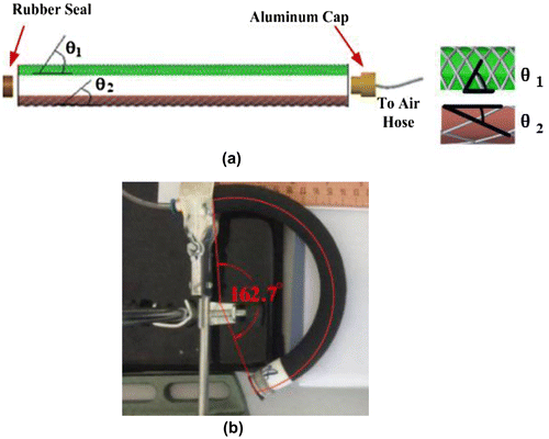
In a previous work (Boran et al., Citation2016), a bimorph-like bending actuator was proposed. Two separate fiber reinforced rubber tubes with different fiber braid angle (θ1 and θ2) were split lengthwise into half and combined by wrapping an additional layer of rubber around the outer surface of half tubes (Figure (a)). As a first step towards the analysis of bending actuators of this type we consider a tube with a single fiber braid angle, which may expand or contract on pressurization but will not bend. This case is modeled by Equation (1), where the output force of the linear pneumatic inflatable actuator is expressed as a function of input air pressure (P), braided angle (θ) and radius of the original internal chamber before inflation or deflation (ro). FEA simulation in previous work has revealed that fiber reinforced rubber tubes with braided angle (θ) greater than 54.7° extend on pressurization (referred to as extensible tubes); in contrast fiber reinforced rubber tubes with θ less than 54.7° contract length-wise on pressurization (contractile tubes). Using this principle bending actuators can be produced by slitting the tubes in half lengthwise and bonding half a contractile rubber tube to half an extensible rubber tube.(1)
(1)
Unlike the previous work where both ends of PBA were encapsulated with aluminum caps, the PBA used in soft gripper was sealed with rubber at one end, and aluminum cap at the other end. The PBA patterned by different braided angles contracts on one side and extends on the other side once air pressure is supplied into the cavity, so that bending displacement is produced as seen in Figure (b).
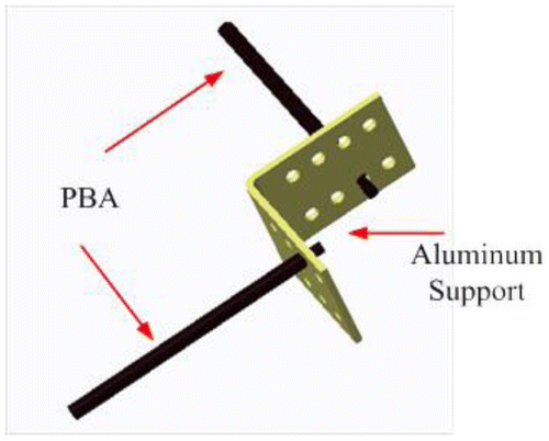
Before the PBA was implemented in the design of soft gripper, the effect of various design parameters was characterized and verified systematically through repetitive quasi-static experiments, such as the length of PBA (L), inner tube diameter (D1), wall thickness (t1), mechanical property of rubber, different combinations of fiber braided angle (θ2 and θ1), number of windings (N), fiber elasticity, cross sectional diameter of fiber threads (D2) and seal thickness (t2) (summarized in Table and illustrated in Figure ). Though these parameters all have an impact on the output bending force and angular displacement of pressurized PBA, only those of significant importance were compared in the development of a soft gripper i.e. length, diameter and wall thickness. The ranking of their impacts was reflected through the number of operators as shown in Table . The selected rubber has a tensile strength of 9.35 MPa and elongation of 375% at break. Vectran® UM fiber was used to create fiber reinforcement accredited to its thermal stability at high temperature, high modulus and low creep. The thickness of the rubber seal was selected as 6 mm to prevent failure due to excessive pressure supply while still minimizing the weight of the PBA. The combination of braided angle was fixed as θ1 = 80° and θ2 = 10°, since this combination produced a large bending displacement and bending force in preliminary test on single piece of PBA (Boran et al., Citation2016). An aluminum support housed the PBA in a gripper configuration where the angle and distance between two fingers was adjustable depending on the size of object to grip (Figure ).
Table 1. Summary of effects of parameters on bending angle, blocking force and robustness against air pressure supply
Figure 2. PBA was characterized against over nine parameters: the length of PBA (L), internal diameter (D1), wall thickness (t1), difference between the braided angle (θ1–θ2), rubber mechanical property (reflected in the coefficients of Ogden hyper-elastic material model), rubber seal thickness (t2), number of windings (N) per unit centimeter, the mechanical property of fiber (reflected in Young’s Modulus and Poisson’s ratio of fiber material) and the radius of rubber (D2).
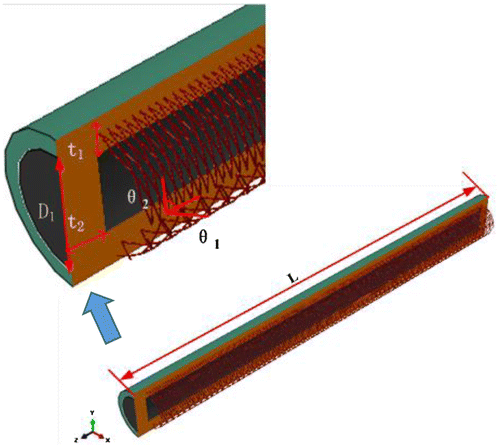
Figure 3. CAD design of experimental configuration and setup.
2.1. FEA simulations
Each PBA was modelled in Abaqus® 6.14 as a cylindrical hollowed elastomeric rubber tube with fibers wrapped in a helix thread pattern at two different braided angle in its circumferential direction. Abaqus® was selected as the modelling tool due to its advantages for analysis of flexible elastic materials. In addition the ability to use Python® scripts for programming parameters in Abaqus’ PDE module directly minimized computation time by avoiding redrawing the complete PBA each time a parameter was changed. The main body of PBA was modelled as a merged solid entity with its fixed end encapsulated by aluminum cap and its free end as a rubber seal. This was because its free end would interact with targeted objects and cannot be a rigid component. Threads of fiber were created by locating an array of points defined geometrically by helical curve along the outer surface of rubber cylinder. Tie constraints were created to bond the fiber braiding, rubber tube and caps, as there was no relative motion between them. An additional layer of rubber tube was finally attached to the outer surface of fiber reinforced rubber layer. The coefficients used in the non-linear hyper-elastic rubber material model to describe the mechanical property of rubber were determined by running uniaxial tensile tests on dumbbell rubber testing specimens according to ISO 37 (Citation2011) and curve-fitting the experimental nominal stress against strain data in Abaqus® 6.14 to determine a best-fit model. ISO 37 describes a method to determine the hyper-elastic mechanical properties of vulcanized and thermoplastic rubbers through measurements of tensile strength, elongation at break, stress at given strain, and stress and elongation at yield.
A three term Ogden model was used to characterize the mechanical property of rubber, where it is the main body of the proposed PBA. In this hyper-elastic material model, the elastic potential energy is expressed as a function against strain along three axes, where, λi represents the strain in each individual orthogonal direction, and μp, αp and Dp denote the coefficients depending on the material properties. The fitted parameters in Abaqus® were given by μ1 = 0.0340, α1 = 1.662, μ2 = 0.02167, α2 = 4.714, μ3 = 0.05987, α3 = −2.197, D1 = D2 = D3 = 0. According to (3), differentiation of elastic potential energy (W) against longitudinal strain (λ1) gives actual relation between engineering stress (σ) and stretch in uniaxial tensile test. The fitted plot of uniaxial nominal stress against nominal strain (λ1 − 1) agrees with the experimental data, with an R2 value of 0.9887. Since exactly the same material has been used in this paper, this formula was not reiterated as a major function to understand the concept of design.
(2)
(2)
(3)
(3)
The relationship between output force and braided angle was developed as (2). By solving (2), it can be seen that a braided angle of 54.7° gives zero strain, which means the PMA reaches its maximum volume and cannot deform any more, therefore no longitudinal force can be produced. Simulation in previous work done by us (Boran et al., Citation2016) has revealed the fiber reinforced rubber tube extends when the braided angle (θ) is greater than 54.7°; whereas contracts length-wisely when θ is less than 54.7°. Accordingly, bending motion could be produced when half of the contractile rubber tube is combined with another half of extended rubber tube. The most important formula is already shown in Equation (1), where the force in pneumatic muscle actuator is expressed as a function of input air pressure (P), braided angle (θ), radius of original internal chamber before inflation or deflation (ro).
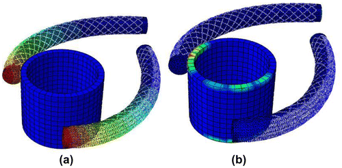
The coefficients (μ1 = 0.0340, α1 = 1.662, μ2 = 0.02167, α2 = 4.714, μ3 = 0.05987, α3 = −2.197) were fed into Abaqus® 6.14 to define the material property of rubber when simulation was run. Since some sharp edges exist in the parts tetrahedral mesh elements were used. Quadratic geometric order and hybrid formulation were selected to consider the interaction between the PBA and gripped objects. The main body of the rubber was meshed with quadratic tetrahedron elements (Type C3D10H). The braided fiber threads, with linear isotropic mechanical properties defined by Young’s modulus and Poisson’s ratio, were modelled as multiple threads of helical wire using quadratic beam elements (Type B32) to give four degrees of freedom to each individual nodal point. Gripped objects of regular shapes used linear hexahedron elements (Type C3D8R). The approximate global size was chosen based on the amount of deformation the PBA underwent and its size, typically chosen between 1 and 2. Non-linear option analysis was activated to consider large deformation. The total number of elements and nodal points depends on the size and shape of objects in the assembly. Unlike some other simulation tools such as ANSYS®, convergence plot cannot be automatically generated in Abaqus® for complex structures with large non-linear deformation. For each pair of PBAs, a convergence study was done by increasing the number of meshed elements manually five times and comparing the output. It showed the force/displacement output at the free end of PBA converged upon given pressure loading. Beyond a certain point, though finer meshing might result in slightly more accurate simulation results, this would come at the expense of unacceptable computation cost. Depending on the dimension of PBA, iterative testing revealed a mesh size between 0.5 and 1 produces adequate simulation results, and further increase in meshing did not necessarily generate a higher level of accuracy but sacrificed efficiency. There were 23,190 elements and 9,308 nodes for the assembly of each single piece of PBA. In order to resemble the digits of gripper, pairs of PBA were placed at a nominal angle of 90° to compare their force and bending capabilities when gripping the targeted objects. In a real application, the PBA pairs could be positioned at any arbitrary angle depending on performance requirements. The size and weight of objects created in Abaqus® 6.14 were made to match them with real objects used in the experimentation. The bending (Figure (a)) and force capability of PBA (Figure (b)) when interacting with targeted objects were simulated. Interactions between the contact surfaces of PBA and the objects were modelled accurately, although it should be noted this was computationally expensive. The friction parameters between the contact surfaces were found by performing repetitive experiments against objects with pressurized PBA. Since quasi-static analysis was run by steadily increasing the air pressure supply into the PBA, the static friction coefficient was taken instead of the kinetic coefficient. A spring balance parallel to the contact surface was connected to the PBA and pulled. The force was gradually increased until it began to slide; and the force reading then became the static friction. The frictional coefficient was computed as the ratio between static friction and weight of PBA. Contact property between PBA and object was defined as tangential in FEA simulation, with the measured static friction coefficient. Contact force was estimated by summing all the normal forces applied to elements along the contact surface on the object. The weight of object that the soft gripper is capable of handling then was estimated by finding the product of normal force and frictional coefficient. The inverse solution to find the required pressure supply given weight and material of object is not achievable with this simulation method, as the pressure supply can be set as external loading only, but not an optimization parameter. In addition, simulation of fiber-reinforcement already adds complexity to simulation and running optimization substantially increased the computing cost.
2.2. Experiment
2.2.1. Hardware setup
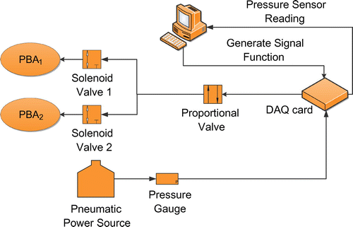
The hardware setup is shown in Figure . The pneumatic control system comprises an electro-pneumatic proportional valve (ITV2050-012L SMC® 0–0.9 MPa) and two 2-way 3-port (3V2-08-NC AirTAC® 0–0.8 MPa) solenoid valves to control the pressure supply to each individual PBA on the gripper. The proportional solenoid valve is also equipped with a pressure sensor used for calibration and accurate feedback control. A feedback controller is implemented in LabVIEW® 2014 with the objective to maintain the pressure at a desired level, so as to maintain the pneumatic bending actuator in a steady-state position and/or gripping force. The two PBAs were controlled individually as described below because it would give flexibility in gripping objects by moving one finger first and then the other.
2.2.2. Control method
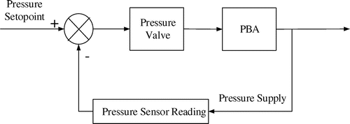
A feedback control loop was implemented to control each single PBA of the soft gripper (Figure ). The solenoid valve was controlled by current, which was then converted to voltage input signal in the interfacing circuit. Hence the output pressure could be adjusted by controlling the input voltage directly in the LabVIEW® 2014 program interface. A targeted operating pressure was set through the voltage input to proportional valve and determined the volume of output force and angular deflection. The current input voltage was compared with the set point continuously at a sampling rate of 1,000 Hz. The output pressure was incremented/decremented continuously until the difference between set point and current value was within a dead zone of 0.01 V (corresponding to 0.0225 bar in output pressure). The PBA would inflate/deflate accordingly and maintained in position until the next command was initiated in LabVIEW® 2014. Since each individual PBA was controlled by a separate switch valve, the activation of one PBA would be independent from the motion of other. To prevent PBA from failure, 0.8 MPa was set as the ceiling pressure supply.
2.2.3. Experimental tests
Testing was performed to evaluate the accuracy of the proposed systematic design as well as the ability of the gripper to handle incremented loading (from 5 g of plastic container to 60 g plastic cup filled with water) and its ability to grip fragile objects without any potential damage. Two PBAs were employed in this design, although in future more could be used in parallel to enhance the ability of soft gripper to lift heavier objects. The friction coefficient (μ) between the contact surfaces and pressure supply (P) were the main factors determining the output gripping force produced by PBA. The size of objects to grip could be adjusted by changing the position of PBA on the aluminum support. When gripping test was run, two samples of PBA for each parameter were taken to study its effects on gripping capability (Table ).
Table 2. Samples of PBA
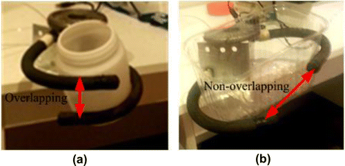
Preliminary tests showed the proposed gripper would produce sufficient bending to grasp objects of different weights and dimensions, such as an egg, plastic milk bottle, rectangular container and plastic cup filled with water etc. As a bending actuator, the proposed gripper is intrinsically capable of gripping objects vertically from above, which has been achieved in the design of a large variety of industrial grippers already. A more challenging type of gripping, which is gripping objects from the side, was focused and tested in this work as seen in Figure . This aims to demonstrate the potential of using the proposed gripper as a safe assistive device for elderly or disabled people. A cylindrical plastic cup (with a maximum of 100 mm diameter, 130 mm high) filled with water was used to test its stability and capability of holding heavy objects (Figure (a)). Water was gradually added into the empty plastic cup to increase the overall weight of cup, and then the final maximum weight before the plastic container dropped was measured. Overlapping between fingers was allowed to wrap the cup around. In Figure (b), a cuboid plastic container with a greater dimension (100 mm × 100 mm × 150 mm) was gripped from its side.
Figure 7. (a) Double fingered soft gripper was used to grip a plastic cup filled with water where overlapping is allowed and (b) Soft gripper was used to grip cuboid plastic container of greater dimension, where the distance between two fingers was adjusted and there was no overlapping.
Compliance testing was performed by gripping a raw egg, and this was compared with the simulation results. A test was run with over a dozen eggs using a controlled experimental setup to replicate the side gripping force and the average required force to break the egg was measured to be 28 N. This is much greater than the maximum point load that the samples of PBA listed in Table is capable of supplying according to the FEA analysis.
3. Results
The results of the cup gripping experiment are given in Table . Looking at Tables and it can be seen that increasing the length has a negative effect in gripping objects, but it plays a positive role if overlapping between PBAs is allowed. In addition, the longer PBA produced more bending displacement, and therefore is more capable of handling objects of small size. A pair of 220 mm PBA positioned (Sample A) at 90°, 2 cm apart could be fully closed with an input pressure of 0.5 MPa, i.e. each individual PBA would be able to produce a bending displacement of around 135°. The shorter PBA (140 mm) could only bend to around 90° with the same pressure input, but it demonstrated a more consistent and stable manner in handling objects. Increase in radius would increase the ability of gripping, in that it generates a greater normal force at the interaction surface. Increase in wall thickness significantly reduces the gripping capability because the bending displacement and output bending force are both decreased.
Table 3. μ = 0.28, p = 0.375 MPa, testing was run on a cylindrical plastic cup
The compliance test was run on eggs by incrementing the pressure input to its maximum allowable value before explosion and observing if the egg was broken. Since the pressure applied was slow and the PBA has high compliance, it did not break the egg before bursting itself. The maximum pressure supply allowable to each individual sample of PBA was listed in Table . The difference between experimental data and simulation results could be due to ignorance of frictions between fiber and rubber in FEA modelling. Increase in wall thickness would significantly improve gripper’s capability of withholding high input air pressure.
Table 4. Maximum air pressure supply allowed for grippers using different samples of PBA
4. Discussion and conclusions
A reasonably good fit was observed between the simulation and experimental data across the parameters tested, which validates the usefulness of FEA modelling for designing PBA-based grippers of this type. According to the results, long slices of PBA were prone to deviate and fall off when they were used to clench objects from the side due to their greater weight. The compliance test shows that proposed soft gripper would not break an egg before it bursts, which means it would absorb the impact energy and has the potential to be applied in delicate environment. The relationship between output force, deflection and the three main parameters are summarized in Table . The discrepancies between simulation and experiment results could be explained by the change in friction coefficient at different pressure levels. Since the rigidity of PBA increased with an increase in pressure input, the friction coefficient decreased and could vary from 10 to 17% depending on the materials of objects. Another candidate reason could be that the constraint between fibre and rubber tube composing the PBA was assumed to be strictly tied in simulation, ignoring any possible friction between them.
Table 5. Weight and size of objects a gripper is capable of handling based on different dimensions; compliance of soft gripper based on changes in dimension
In this paper, an easily accessible fabrication technique was used to manufacture the proposed soft PBA. A systematic design of soft gripper was presented and verified by comparing the experimental and analytical simulation results on its ability to grip using a quantitative intuitive method. Though the simulation method might induce more computational complexity, it provides detailed understanding of the force and bending capability of the proposed soft gripper when interacting with targeted objects. The overall trend of experimental results follows the simulation results reasonably well. The proposed soft gripper has been practically validated to successfully grasp objects without requiring complex control as generally pneumatic actuators are force compliant themselve. These grippers are based around PBAs that produce no radial bulging when pressurized, and hence shows great potential in dealing with delicate objects in both manufacturing and medical applications. Further research will focus on improving the presented simulation method by providing techniques to automatically optimize design parameters to achieve a required output force and bending displacement given weight and material of objects to grasp, such as topology, sizing and shape optimization. The mechanical hardware could also be improved to achieve more advanced functionality in potential industrial and/or medical applications.
Additional information
Funding
Notes on contributors
Kean C. Aw
The Microsystem and Smart Materials research group is part of the Mechatronics engineering community in the Mechanical Engineering department at the University of Auckland. This group has been very active in the development of sensors and actuators to solve many different problems. In particular, this current research in soft pneumatic bending actuators has great significance in the on-going research in medical rehabilitation systems such as gait rehabilitation, stroke rehabilitation, etc as this actuator will simplify design, reduces the weight of the rehabilitation system, making the overall system less bulky. Additionally, this actuator is low cost and simple to fabricate.
References
- Bauer, S., Bauer-Gogonea, S., Graz, I., Kaltenbrunner, M., Keplinger, C., & Schwödiauer, R. (2014). 25th anniversary article: A soft future: from robots and sensor skin to energy harvesters. Advanced Materials, 26, 149–162.10.1002/adma.201303349
- Boran, W., Aw, K. C., Morteza, B. A., & McDaid, A. J. (2016). Design and fabrication of a fiber-reinforced pneumatic bending actuator. In International Conference on Advanced Intelligent Mechatronics. Banff: IEEE.
- Che-Ming, B. C., John, B., Manu, V., Carlo, M., & Parameswaran, M. (2011). Bending fluidic actuator for smart structures. Smart Materials and Structures, 20, 1–8.
- Gorissen, B., De Volder, M., De Greef, A., & Reynaerts, D. (2011). Theoretical and experimental analysis of pneumatic balloon microactuators. Sensors and Actuators A: Physical, 168, 58–65.10.1016/j.sna.2011.03.057
- Gorissen, B., Donose, R., Reynaerts, D., & De Volder, M. (2011). Flexible pneumatic micro-actuators: Analysis and production. Procedia Engineering, 25, 681–684.10.1016/j.proeng.2011.12.168
- Gorissen, B., Vincentie, W., Al-Bender, F., & Reynaerts, D. (2013). Modeling and bonding-free fabrication of flexible fluidic microactuators with a bending motion. Journal of Micromechanics and Microengineering, 23, 045012–045012.10.1088/0960-1317/23/4/045012
- Hirai, S., Masui, T., & Kawamura, S. (2001). Prototyping pneumatic group actuators composed of multiple single-motion elastic tubes. Proceedings - IEEE International Conference on Robotics and Automation, 4, 3807–3812.
- Howard, A. M., & Bekey, G. A. (2000). Intelligent learning for deformable object manipulation. Autonomous Robots, 9, 51–58.10.1023/A:1008924218273
- ISO 37. (2011). Rubber, vulcanized or thermoplastic – Determination of tensile stress-strain properties.
- Kadowaki, Y., Noritsugu, T., Takaiwa, M., Sasaki, D., & Kato, M. (2011). Development of soft power-assist glove and control based on human intent. Journal of Robotics and Mechatronics, 23, 281–291.
- Koichi, S., Shuichi, W., Kenta, M. & Kazuhiro, I. (2013). Long bending rubber mechanism combined contracting and extending fluidic actuators. In IEEE/RS International Conference on Intelligent Robots and Systems (pp. 4454–4459). Tokyo: IEEE.
- Konishi, S., Nokata, M., Jeong, O. K., Kusuda, S., Sakakibara, T., Kuwayama, M., & Tsutsumi, H. (2006). Pneumatic micro hand and miniaturized parallel link robot for micro manipulation robot system. In Proceedings 2006 IEEE International Conference on Robotics and Automation, 2006. ICRA 2006 (pp. 1036–1041). Orlando, FL. doi:10.1109/ROBOT.2006.1641846
- Martinez, R. V., Branch, J. L., Fish, C. R., Jin, L., Shepherd, R. F., Nunes, R. M. D., … Whitesides, G. M. (2013). Robotic tentacles with three-dimensional mobility based on flexible elastomers. Advanced Materials, 25, 205–212.10.1002/adma.201203002
- Michäel, D. V., & Dominiek, R. (2010). Pneumatic and hydraulic microactuators: A review. Journal of Micromechanics and Microengineering, 20(4), 1–18.
- Michael, W., Michael, T. T., Yiğit, M., Yong-Lae, P., Annan, M., Ye, D., … Robert, J. W. (2014). Pneumatic energy sources for autonomous and wearable soft robotics. Soft Robotics, 1, 263–274.
- Onal, C. D., & Rus, D. (2012). A modular approach to soft robots. In 2012 4th IEEE RAS & EMBS International Conference on Biomedical Robotics and Biomechatronics (BioRob) (pp. 1038–1045). Rome. doi:10.1109/BioRob.2012.6290290
- Robot Manipulation of Deformable Objects. (2000). Advanced manufacturing. London: Springer-Verlag.
- Suzumori, K., Iikura, S., & Tanaka, H. (1991). Development of flexible microactuator and its applications to robotic mechanisms. Proceedings 1991 IEEE International Conference on Robotics and Automation (pp. 1622–1627). Sacramento, CA: IEEE10.1109/ROBOT.1991.131850
- Suzumori, K., Wakimoto, S., Miyoshi, K., & Iwata, K. (2013). Long bending rubber mechanism combined contracting and extending tluidic actuators. In Long bending rubber mechanism combined contracting and extending tluidic actuators (pp. 4454–4459). Tokyo. doi:10.1109/IROS.2013.6696996
- Trivedi, D., Rahn, C. D., Kier, W. M., & Walker, I. D. (2008). Soft robotics: Biological inspiration, state of the art, and future research. Applied Bionics and Biomechanics, 5, 99–117.10.1155/2008/520417
- Yang, Y., & Chen, Y. (2016). Novel design and 3D printing of variable stiffness robotic fingers based on shape memory polymer. In 2016 6th IEEE International Conference on Biomedical Robotics and Biomechatronics (BioRob) (pp. 195–200). Singapore doi:10.1109/BIOROB.2016.7523621
- Yoel, S., Alon, W., & Kosa, G. (2011). Bi-bellows: Pneumatic bending actuator. Sensors and Actuators A: Physical, 167, 484–494.

