 ?Mathematical formulae have been encoded as MathML and are displayed in this HTML version using MathJax in order to improve their display. Uncheck the box to turn MathJax off. This feature requires Javascript. Click on a formula to zoom.
Abstract
A simple, first-principles mathematical model has been developed to analyze the effect of interfacial and bulk charge transfer on the power output characteristics of dye-sensitized solar cells (DSSCs). Under steady state operating conditions, the Butler-Volmer equation and Schottky barrier model were applied to evaluate the voltage loss at counter electrode/electrolyte and TiO2/TCO interfaces, respectively. Experimental data acquired from typical DSSCs tested in our laboratory have been used to validate the theoretical J–V characteristics predicted by the present model. Compared to the conventional diffusion model, the present model fitted the experimental J–V curve more accurately at high voltages (0.65–0.8 V). Parametric studies were conducted to analyze the effect of series resistance, shunt resistance, interfacial overpotential, as well as difference between the conduction band and formal redox potentials on DSSCs’ performance. Simulated results show that a “lower-limit” of shunt resistance (103 Ωcm2) is necessary to guarantee a maximized efficiency. The model predicts a linear relationship between open circuit voltage (Voc) and photoanode temperature (T) with a slope of −1 mV/°C, which is close to the experimental data reported in literature. Additionally, it is observed that a small value of overpotential (2.2 mV) occurs at the short-circuit condition (Jsc = 10.5 mA/cm2), which is in a close agreement with Volmer-Butler equation. This observation suggests that, compared to the maximum attainable voltage (700 mV), the overpotential values are small and can be neglected for platinum catalyst based DSSCs.
Public Interest Statement
Dye-sensitized solar cells (DSSCs), as a promising PV technology, have opened up one of the most hopeful prospects to meet the increasing demand for clean, renewable energies. This research article presents a mathematical model of DSSCs, based on interfacial and bulk charge transfer processes, which was used to illustrate the impact of various operating conditions, cell design parameters, and materials properties. It was found that, compared to the conventional diffusion model, the presented model fitted the experimental data more accurately especially at high voltages. Clearly, a linear relationship was observed between open-circuit voltage and photoanode temperature with a slope of −1 mV/°C, which is close to the literature reported values. This bulk and interfacial model gives an insight into the relation between physical processes in DSSCs and overall cell performance. More importantly, this model could be utilized to accelerate the commercialization process with substantial savings of experimental time and resources.
1. Introduction
During the last two decades, dye-sensitized solar cells (DSSCs) have received a considerable amount of research attention due to their low production cost, lightweight, and mechanical flexibility (Gong, Liang, & Sumathy, Citation2012; Gong, Sumathy, & Liang, Citation2012; Gong et al., Citation2015). A high-efficiency DSSC depends on a series of physical processes, such as good visible light harvesting, efficient charge separation, fast charge transport and low recombination rate. To date, light-to-electrical energy conversion efficiencies over 15% have been achieved, which is comparable to that of amorphous silicon solar cells (Heo et al., Citation2013). To further improve the device efficiency, many new materials have been synthesized and applied in DSSCs. Although these materials could generate promising outcomes, the new device structures have also posed a challenge for analyzing the physical processes and operational parameters. A deep understanding of physical mechanisms which govern the device operation is essential for future development.
The mechanism of dye-sensitized solar cells can be understood through equivalent circuits, which are considered to be a useful tool to analyze cell devices and improve cell performance. The information obtained from the equivalent circuit model of DSSCs includes physical processes (Han, Koide, Chiba, & Mitate, Citation2004), system simulation (Huang et al., Citation2009), and cell modules (Giannuzzi, Manca, & Gigli, Citation2013). One of the major advantages of equivalent circuit model is that it avoids cumbersome use of a number of physical and chemical parameters, but instead projects the PV system as a combination of a minimal number of electrical circuit elements. In addition, it does not require combined analyses of EIS and J–V data, and thus is suitable for any routine analysis of DSSCs.
Equivalent circuit along with first-principles modeling provides a means to understand the photoelectric conversion process in solar cells, and enables the design of high efficiency devices. Ferber, Stangl, and Luther (Citation1998) developed an electrical model of DSSC which integrates physical charge transport processes with interfacial chemical reactions. Their model was later adopted by many researchers as the framework (Bavarian, Nejati, Lau, Lee, & Soroush, Citation2013; Belarbi, Benyoucef, Benyoucef, Benouaz, & Goumri-Said, Citation2015; Gentilini et al., Citation2010; Joshi, Korfiatis, Potamianou, & Thoma, Citation2013; Korfiatis, Potamianou, & Thoma, Citation2008). To study coupled charge transport in DSSCs, Fredin, Ruhle, Grasso, and Hagfeldt (Citation2006) presented a simulation platform-SLICE to exclusively study the influence of ions in the electrolyte on electron transport in the nanoporous medium. The results showed that when the ionic concentration is sufficiently high, the effective permittivity coefficient, ε, has no influence on the electron transport. Beyond the simulators built upon one-dimensional models, Miettunen, Halme, Visuri, and Lund (Citation2011) developed a transient two-dimensional model to study the lateral inhomogeneity and edge effects in DSSCs. The Nernst-Planck equations in 2D format were solved numerically using COMSOL Multiphysics software. It was revealed that a small difference in the size between photoanode and counter electrode can significantly change the lateral current density distribution as well as the time to reach steady state. In order to model innovative DSSC topologies, Gagliardi, Auf der Maur, Gentilini, and Di Carlo (Citation2009, Citation2011a) recently developed a three-dimensional simulator (TiberCAD), which permits simulation on 1D, 2D, and 3D cell configurations. Using this simulator, Gagliardi, Auf der Maur, Di Carlo, and Carlo (Citation2011b) simulated the performance of an optical fiber wrapped DSSCs, which provides helpful guidance for the design of novel cell structures.
This paper reports a first-principles mathematical model of a DSSC, based on the electrical model developed by Ferber et al. Butler-Volmer equation and Schottky barrier model are integrated with the electrical model to include the interfacial voltage loss at counter electrode/electrolyte and TiO2/TCO interfaces, respectively. Parametric studies were conducted to analyze the effect of electrical resistance, interfacial voltage loss, and operating temperature on DSSC performance. Experimental data acquired from a typical high-efficiency DSSC were used to quantitatively validate the proposed model. Based on the framework built in our previous study (CitationGong, Sumathy, & Liang, 2016), in-house codes were developed to solve differential equations using relaxation method and simulation has been carried out using MATLAB (Press & Teukolsky, Citation2007).
2. Mathematical model
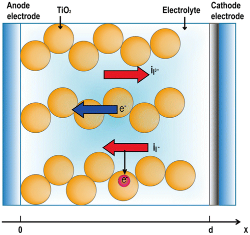
The DSSC system is composed of two conducting electrodes and an electrolyte solution containing a redox couple . The electrodes are constructed on glass substrates and are coated with a transparent conducting oxide (TCO) layer. The working electrode (anode) consists of a dye-sensitized titanium dioxide (TiO2) layer deposited on the TCO glass substrate, and the counter electrode is made of catalyst materials such as platinum to promote the reduction of the oxidized redox couple in the electrolyte. When sunlight strikes the cell, the dye sensitizers get excited and thereby generate electrons, which in turn get directly injected into the conduction band of TiO2. The injected electrons diffuse to the anode and are utilized to do electrical work at external load. Finally, these electrons are collected by the electrolyte at counter electrode to complete the cycle. In this study, the DSSC cell has been modeled as a one-dimensional, homogeneous medium consisting of nanoporous semiconductor TiO2, dye, and redox electrolyte, which are intermingled with each other as shown in Figure . The continuity and transport equations are applied to all mobile charge carriers including electrons in the TiO2 conduction band and
ions as well as cations in the electrolyte solution. Assuming DSSCs operate under steady-state conditions, the spatial distribution of charge carriers determines the important electrical characteristics such as J–V curves and maximum power output.
Figure 1. Schematic model for dye-sensitized solar cells (CitationGong et al., 2016).
2.1. Equations of continuity
The relaxation dynamics of photoinduced electrons in Ruthenium dye-sensitized TiO2 solar cell is schematically shown in Figure . The forward process 1, 2, and 3 correspond to (i) photoexcitation of dye sensitizers, (ii) photogenerated electron injection into the conduction band (CB), and (iii) dye regeneration, respectively. In addition to the forward electron transfer and transport processes, the model also illustrates several competing electron loss pathways, including (a) excited dye molecules fall to ground state, (b) recombination of injected electrons with oxidized dye molecule S+, and (c) recombination of injected electrons with .
(1)
(1)
(2)
(2)
(3)
(3)
(a)
(a)
(b)
(b)
(c)
(c)
Figure 2. Kinetics of the RuL2(NCS)2 dye-sensitized TiO2 solar cell with redox mediator (CitationGong et al., 2016).
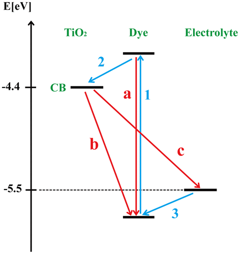
where S is the dye sensitizer; S* is the electronically excited dye sensitizer; S+ is the oxidized dye sensitizer; and is the redox couple.
Previous experimental studies have found that the photoexcitation occurs in the femtosecond time range of ~10−15 s, which is approximately 3 orders of magnitude faster than the relaxation of excited dye molecules (path-a). The characteristic time scales of the processes 2 and 3 are estimated to be ~10−12 and ~10−8 s, respectively. These processes are fast enough that they are considered to be instantaneous processes that occur after photoexcitation. Therefore, in this study, the electron generation is assumed to have a unit quantum efficiency (Boschloo & Hagfeldt, Citation2009), and the electron generation rate Ge(x) is given by(4)
(4)
where is photon flux density obtained from AM1.5 global solar spectrum, with 11% reduction in reflectance and absorptance caused by the TCO glass;
is the light absorption coefficient of the sensitizing dye at wavelength
; and x is the coordinate along the direction of cell thickness as shown in Figure . The illumination enters from the front side (x = 0). Ruthenium complex RuL2(NCS)2, also known as N719 dye, is used as light-absorbing dye sensitizer and the light absorption coefficient
is defined as
(5)
(5)
In the above equation, refers to the molar absorptivity of dye sensitizers, and Cdye represents the concentration of dyes absorbed in the cell. Cdye is determined by the surface concentration (σ), cell thickness (d), and the roughness factor (Rf) of TiO2 layer, which can be calculated by:
(6)
(6)
where σ represents the concentration of dye adsorbed on an ideal (virtual) flat surface of TiO2 as a monolayer and the value is estimated to be (Murakoshi et al., Citation1995; Nazeeruddin et al., Citation1993).
Compared with forward processes, the backward processes are much slower. As shown in Figure , the relaxation of excited dye (path-a) and electron recombination in TiO2 with dye (path-b) are only at the time scale of ~10−9 and ~10−6 s, respectively. Therefore, both recombination paths have been neglected. However, the electron recombination with (path-c) has a high recombination rate (
) and hence this loss mechanism has been accounted in this model. When DSSCs operate under stationary state with illumination, the electrons in the conduction band have a recombination rate Re expressed as (Oda, Tanaka, & Hayase, Citation2006),
(7)
(7)
where ke denotes the electron recombination rate constant; ne and are electron concentration under illumination and in equilibrium, respectively. While
and
represent the iodide and triiodide concentration under illumination, the
and
represent the concentrations without any illumination (under equilibrium conditions). Under operating conditions, the second term on the right-hand side of Equation (7) can be neglected because the electron concentration
is much lower compared to ne. However, it becomes important when J–V dark curves have to be calculated under dark conditions.
To calculate the concentration of charge carriers, the continuity equations have been applied for each of four charged species including electrons, triiodide/iodide ions, and cations. According to the stoichiometry of the triiodide-iodide reaction (see Section 2.1), the generation of two electrons is always linked to the production of one triiodide ions and the consumption of three iodide ions. Thus, continuity equations corresponding to four charged species are expressed as,(8)
(8)
(9)
(9)
(10)
(10)
(11)
(11)
where ‘e0’ denotes the elementary charge; je, ,
, and jc are current densities of electron, iodide, triiodide and cation, respectively. The cation current density is nullified, since the cations are not involved in any chemical reactions.
2.2. Transport equations
The movement of all four charged spices can be described by transport equations. The current densities of each species are correlated to their concentration (ne, ,
, and nc) through Equations (12)–(15). In each equation, the first and second terms on the right-hand side originate from the diffusion due to the concentration gradient and the drift (migration) due to the electric field, respectively.
(12)
(12)
(13)
(13)
(14)
(14)
(15)
(15)
where De, ,
, and Dc refer to the effective diffusion constant, while μe,
,
, and μc denote the charge mobility of each species. For the same charged species, D and μ are connected through Einstein relation,
(16)
(16)
where k is the Boltzmann constant, and T represents operating temperature. The macroscopic electric field E in the cell is related to the charge concentrations though Poisson’s equation:(17)
(17)
where and
represent the permittivity of free space and relative dielectric constant, respectively. The above formulated differential equations represent a dynamic mathematical model. Solving these equations with appropriate boundary conditions allows one to predict the electrical characteristics of DSSCs based on their internal physical parameters such as the distribution of current density, electrical field, effective diffusion coefficients, and recombination rate constant.
2.3. Boundary conditions
The presented model consists of six coupled non-linear, ordinary differential equations (ODEs): one continuity equation [Equation (8)], four transport equations [Equations (12)-(15)], and the Poisson’s equation [Equation (17)]. These ODEs correspond to six independent variables (electron current density, concentration of four charged spices, and internal electric field). According to the conservation of particles in electrolyte, the concentration of cations and iodine atoms are assumed to be constant, which leads to the following integral boundary conditions:(18)
(18)
(19)
(19)
As mentioned in Section 2.1, the generation of two electrons always leads to the consumption of three iodide ions, therefore,(20)
(20)
Due to charge neutrality within the cell boundary, the summation of negative charge exactly equalizes the overall positive charge,(21)
(21)
It is noted that effective concentrations and
are obtained from multiplying the initial concentration
and
by the porosity (p) of TiO2 layer.
As TCO substrate is highly conductive, its contact with TiO2 semiconductor is considered to be ohmic (Gong, Sumathy, Qiao, & Zhou, Citation2017). Hence no surface charge exists at TCO/TiO2 interface, and the macroscopic electric field is assumed to be zero at the front contact (x = 0),(22)
(22)
Also, since the charged species in the electrolyte are limited within the inner cell, the current flow across the boundary is only carried by electrons. Therefore, the following boundary conditions hold valid:(23)
(23)
(24)
(24)
where jg is net current density. Current density at counter electrode (x = d) equals to net current density and can be expressed as:(25)
(25)
where j0 is the exchange current density at counter electrode, β is the symmetry parameter, is the concentration of iodide in open circuit,
is the concentration of triiodide in open circuit, Upt is the overpotential. The overpotential depends on the catalytic activity of counter electrode and is needed to drive the reaction at certain current density. It can be defined as a deviation of redox energy ERedox in operation from equilibrium
in open-circuit conditions
(26)
(26)
The is given by Nernst’s equation,
(27)
(27)
where indicates the formal potential which is approximated by the standard redox potential
, and the standard concentration nSt of “1 mol/l” is used as the reference concentration.
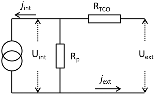
The internal voltage Uint shown in equivalent electrical circuit (Figure ) is determined by the redox potential ERedox, quasi-Fermi level , as well as the voltage loss (Ul) at the TiO2/TCO interface.
(28)
(28)
The Fermi-level depends on the energy level of the conduction band edge (ECB) as well as electron concentration ne(0) in TiO2 conduction band. Their relationship is quantified by
(29)
(29)
where NCB reflects the effective density of states in the TiO2 conduction band, which is defined as(30)
(30)
where represents effective electron mass and “h” is the Planck’s constant.
2.4. Schottky barrier effect
As shown in the Equation (28), the voltage loss “Ul” at TiO2/TCO interface plays a role in determining the actual internal voltage (Uint). The Ul can be evaluated using Schottky barrier model (Gong & Sumathy, Citation2012), in which TCO substrate is considered as a metal due to its high electrical conductivity. Since TiO2 material is an n-type semiconductor and TCO being highly conductive, the TiO2/TCO contact can be treated as an n-type semiconductor with metal contact. Therefore, the voltage loss (Ul) depends on both Schottky barrier height (SBH) and current density (jg) at the TiO2/TCO interface. The quantitative relationship between SBH and current density is derived based on the thermionic-emission theory:(31)
(31)
and(32)
(32)
where h is the Planck constant equivalent to 6.626 × 10⁻³⁴ m2 kg s-1, m* is effective electron mass equal to 5.6 times the electron mass me, A* is the Richardson constant of TiO2 equal to 6.71 × 10⁶ Am-2 K-2, and is the Schottky barrier height. The voltage loss can be expressed as a function of photocurrent:
(33)
(33)
2.5. Equivalent circuit
An equivalent circuit is constructed to include other factors such as sheet resistance (RTCO), shunt resistance (Rp), and external resistance (Rext). RTCO is the series resistance due to the TCO layers, and Rp represents the shunt resistance due to internal leakages in the cell. The external resistance, Rext, indicates the electrical load. The internal current is determined by the current density at x = 0, and the cell area:(34)
(34)
Based on the equivalent circuit, the external current Iext is obtained based on Kirchhoff’s laws:(35)
(35)
The internal voltage equals the voltage drop across the TCO and the external resistance.(36)
(36)
Combining Equations (26)–(29) and (36), an expression of Upt can be obtained. Substituting Upt into the current-overpotential equation (25), along with boundary condition Equation (24), yields a combined boundary condition at x = 0 and x = d.(37)
(37)
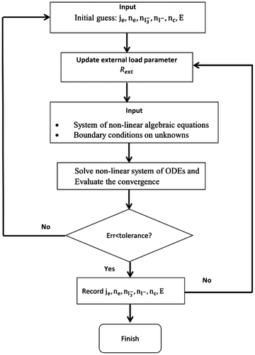
By varying Rext, complete J–V curves can be obtained. It should be noted that the above listed boundary condition, combining values of variables at both points x = 0 and x = d, are numerically unfavorable. However, this problem can be resolved by adding additional trivial differential equations with appropriate local boundary conditions (Ferber et al., Citation1998). Due to the Poisson’s equation, the ODEs are extremely stiff and hence more grid points need to be meshed particularly on the boundaries. A relaxation method can solve the ODEs efficiently with 150 grid points for each variable. The flow chart of the simulation program is shown in Figure . The calculation begins from open-circuit condition (Rext→∞) using equilibrium values as an initial input estimate. The initial values are compared to a solution calculated by the relaxation method to calculate/check the relative error. If the error is greater than a specified tolerance, the solution replaces initial values and the procedure is repeated. Once the error is less than the tolerance, the solution is recorded and used as an initial estimate for a reduced Rext. The above described procedure is carried out for each Rext value until Rext reaches zero (short-circuit condition).
The non-dimensionalization is a useful tool to facilitate numerical solution of the governing equations. It minimizes the direct dependence on the constants by using ratio of constants. Additionally, the non-dimensionalized numerical equations can be solved in much less time, and is also less prone to instability. The ordinary differential equations (ODEs) in this model can be non-dimensionalized using the following dimensionless variables:(38)
(38)
For the sake of brevity, the dimensionless model equations are not given here.
3. Experimental procedure
The DSSC devices were fabricated using TiO2 nanoparticles, Pt-coated counter electrode, and redox electrolyte. The schematic of cell configuration is included as an inset in Figure . A detailed fabrication procedure adopted in this study has been described by the authors (Sigdel et al., Citation2015; Zhou et al., Citation2016). The resultant DSSCs were tested at the Center for Advanced Photovoltaics and Sustainable Energy, South Dakota State University. Under standard 1 Sun illumination conditions, the power conversion efficiency was measured to be 7.6%, which is relatively low compared to commercially available solar cells (e.g. mono/multi-Si, 16%). The low efficiency can be mainly attributed to two reasons: the insufficient light absorption and low electron mobility. Related parametric studies had been carried out in our previous work (CitationGong et al., 2016).
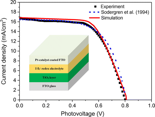
Figure 5. Validation of the present numerical model with the experimental results. The fit parameters of the calculated curve are: Rp = 1 kΩ, RTCO = 12 Ω, ke = 100 s−1, dye concentration = 10 × Cdye; other parameters as in Table . The fit parameters of simple diffusion model are: τ = 100 ms; other parameters same as in (Soedergren et al., Citation1994).
3.1. Preparation of photoanodes
Substrates were prepared under ambient conditions and all chemicals were used without further purification. First, the TEC8 FTO-coated glasses (~8 Ω/sq sheet resistivity, purchased from Hartford Co.) were cleaned with a 2% solution of anionic detergent (Sodium dodecyl sulfate, 99% purity) diluted in deionized water. Next, the glass substrates were rinsed with deionized water, acetone and ethanol, before being dried with clean nitrogen gas. An acidic solution of titanium isopropoxide in ethanol was coated onto the clean substrates through two consecutive spin-coating steps at 4,000 rpm and 3,000 rpm for 40 and 20 s, respectively. The substrate was then dried on a hot plate at 115°C for 15 min and sintered at 475°C for 30 min to form a compact n-type of TiO2 layer. Finally, ~10 μm thick TiO2 layer (Solaronix Ti-Nanoxide T/SP) was doctor bladed on an FTO-glass substrate, followed by deposition of ~4 μm thick reflective layer (Solaronix Ti-Nanoxide R/SP) and treatment in TiCl4 aqueous solution (0.2 M, optimum concentration) at 80°C for 30 min. After each step, the sample was dried at 115°C for 15 min and then sintered at 475°C for 30 min to remove organic components. The resulting film was then immersed in dye solution containing 0.3 mM Ruthenizer 535-bisTBA dye (N-719) in acetonitrile/t-butanol at volume ratio of 1:1 for 30 h at room temperature. Lastly, the photoanode was kept in acetonitrile for 3 h to remove any excess dye.
3.2. Assembly of the DSSCs
Platinum (Pt) precursor solution (0.02 M H2PtCl6 5H2O in anhydrous ethanol) was spin-coated on an FTO-glass substrate at 2,000 rpm for 20 s. The substrate was then heated at 400°C for 15 min in the oven to obtain a counter electrode (CE). An electrolyte containing 0.03 M I2, 0.60 M 1-butyl-3-methylimidazolium (BMII), 0.10 M guanidine thiocyanate, and 0.50 M tert-butylpyridine in acetonitrile and valeronitrile (85:15, volume ratio) was then injected into the cells through the reserved channel. The procedure was complete after the channel was sealed by hot glue. Thus, the fabricated DSSCs had a resulting active area of 0.125 cm2.
3.3. Current density and voltage characteristics
The J–V characteristics of the DSSCs were measured under simulated AM 1.5 sunlight at a light intensity of 100 mW/cm2. A 300 Watt Xenon lamp (Newport 67005) equipped with KG-5 filter was used as light source to simulate the standard AM 1.5 sunlight. The light intensity was calibrated using a National Renewable Energy Laboratory (NREL) certificated Si reference cell and the spectral mismatch factor was estimated to be less than 1%. Both the reference and test cells were ensured to be placed at the same spot under the solar simulator during measurement. The J–V characteristics of the DSSCs were measured using an Agilent 4155C semiconductor parameter analyzer to record the generated photocurrent upon the application of an external potential bias. The voltage was swept in the direction of short circuit to open circuit to obtain a complete J–V curve.
4. Results and discussion
The numerical model developed in the previous section has been used to predict experimental results and assess the effect of key parameters on the performance of dye-sensitized solar cells. The performance can be expressed in terms of overall device efficiency and maximum power output. In order to validate the proposed numerical model, simulation of typical dye-sensitized solar cells has been carried out to fit the experimental measurements. The values of the basic input parameters used in the simulation are listed in Table and the fitting parameters are listed in the caption of Figure . It can be seen from Figure that the DSSC behaves like a near constant current source for low values of voltage (under 0.5 V) and the current is close to short-circuit current Jsc. When the voltage increases, the current begins to decrease exponentially and reaches zero at open-circuit voltage (Voc). The trend in photocurrent density has been captured through our simulation, and the J–V curve generated by the presented model is in close agreement with the experimental data. However, there appears to be a minor discrepancy at the maximum power point, which might be due to the overestimated fill factor (FF) value. This overestimation reflects the additional internal resistance caused by the electrolyte layer (Oda et al., Citation2006), which has not been accounted in the proposed model.
Table 1. Base case parameters used for simulation of dye-sensitized solar cells
Apart from the model being validated using experimental data, it was also compared with the diffusion model developed by Soedergren, Hagfeldt, Olsson, and Lindquist (Citation1994). This simple diffusion model is widely adopted because it provides an analytical solution in terms of J–V characteristics, which in turn facilitates study of the cell parameters such as thickness, diffusion coefficient, and electron lifetime (Ni, Leung, & Leung, Citation2008; Ni, Leung, Leung, & Sumathy, Citation2006). It can be seen in Figure that the simple diffusion model marginally overpredicts the current output at high voltages. This may be due to the fact that the said model does not include an equivalent circuit and therefore the effects of series resistance RTCO and shunt resistance Rp (representing internal leakage) have not been considered. Studies have shown that both RTCO and Rp are critical in dictating the photovoltaic performance of DSSCs (Noh, Ahn, & Riu, Citation2012), and hence it is essential to take into account of those variables to accurately predict the J–V characteristics. In practice, increasing the shunt resistance and decreasing the series resistance could lead to a higher FF value, thus resulting in greater efficiency and pushing the power output of the DSSC closer toward its theoretical maximum.
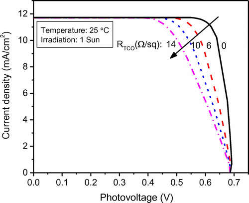
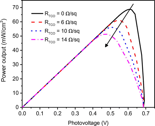
The DSSC performance is a function of design parameters as well as operating parameters and material properties. In order to study the effect of important parameters, other parameters that affect system performance have been specified as listed in Table . The proposed model was utilized to investigate the effect of sheet resistance RTCO of transparent conductive oxide (TCO) layer on the glass substrate. The simulated results show that DSSC performance is sensitive to the sheet resistance. Sheet resistance of TCO plays a major role contributing to the series resistance which in turn has a strong influence on the filling factor of the J–V curve and maximum power output. As shown in Figure that, the “squareness” of the J–V curve decreases with an increase in the RTCO from 0 to 14 Ω/sq which reflects a low fill factor. This reduced fill factor in fact has a negative impact on the power output. For instance, at the given open-circuit voltage and short-circuit current, the maximum power output decreases proportionally with the fill factor as shown in Figure . However, it should be noted that even a minimal reduction in RTCO could remarkably improve power output as well as the device efficiency. The reduction of RTCO is not easy to achieve in actual experiments. In practice, indium tin oxide (ITO, In2O3:Sn) film exhibits an excellent low sheet resistance (ca. 6 Ω/sq) along with an ideal transparency (>80%); however, its low resistance property could deteriorate drastically during the high temperature calcination process (DSSCs fabrication). As an alternative, fluoride-doped tin oxide (SnO2:F, FTO) with a similar structure and comparable sheet resistance has been widely used due to its capability of withstanding high calcination temperatures. It is critical to develop low-resistivity TCO substrate for large-scale DSSCs, since the high resistivity of substrates will not only affect the power output but also lead to a lower optimal width in the DSSC module (Huang et al., Citation2009).
Figure 7. The effect of the sheet resistance RTCO on the power–voltage characteristics of the modeled DSSC.
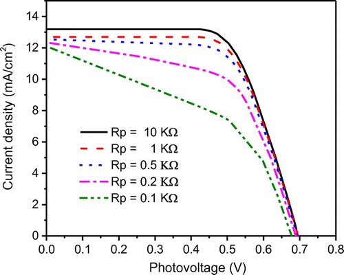
Yet another important parameter that influences the cell performance is the shunt resistance (Rp). In conventional pn-junction solar cells, the shunt resistance represents the leakage across the pn-junction around the edge of the cell and the presence of crystal defects and/or impurities in the junction region. Similarly, in DSSC, a shunt resistance is added to an equivalent circuit to describe the back-electron transfer across the TiO2/dye/electrolyte junction which generally occurs in the dye-free regions of the electrodes (Koide, Islam, Chiba, & Han, Citation2006). The effects of shunt resistance on the J–V characteristics are plotted in Figure . The J–V characteristics are obtained by varying Rp value from 0.1 to 10 kΩ. As expected, for any given junction voltage, the lower the shunt resistance, the lower the current density is. This is because, as the shunt resistance decreases, the current leakage increases. It can also be seen in Figure , that as the shunt resistance decreases, the voltage-controlled portion of the J–V curve begins to sag towards the origin at low Rp, resulting in a significant decrease in the short-circuit current and a marginal reduction in Voc. Note when the shunt resistance value becomes very low (Rp < 0.1 kΩ), a significant reduction in both Jsc and Voc are realized. This is because at low Rp the electron recombination rate becomes high between TiO2 electrode and electrolyte. For any given DSSC, this “lower-limit” of Rp could be quantified by evaluating the slope of the J–V curve at short-circuit current point. Typically, it is recommended to design a DSSC towards maximum efficiency, i.e. to ensure that Rp value is close to the order of 103 Ωcm2 (under ideal conditions). Research has shown that a high shunt resistance (Rp) can be achieved through TCO surface passivation (Amiri & Salavati-Niasari, Citation2015).
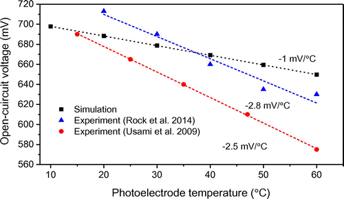
Apart from shunt resistance, photoanode temperature (T) also has an impact on the attainable open-circuit voltage (Voc). The dependence of the open-circuit voltage on photoanode temperature is shown in Figure . It can be seen that as the photoanode temperature increases from 10 to 60°C, open-circuit voltage decreases from 700 to 650 mV. This can be attributed to two factors: the change in electron density (ne) and the shift in TiO2 conduction band edge. As shown in Equation (28), the electron density (ne) has a strong influence on the quasi-Fermi level of TiO2 (EF), which in turn determines the maximum attainable open-circuit voltage in theory (EF − ERedox). As seen in Figure , there exists a linear relationship between Voc and T with a slope of −1 mV/°C, which is in agreement with the literature reported experimental data (ca. −2.5 mV/°C) (Rock, Shi, Garland, & Roy, Citation2014; Usami et al., Citation2009). Compared with the experimental data, the predicted slope is gentler due to the fact that the proposed model has not accounted of the shift in TiO2 conduction band edge potential. Previous study has shown that Voc dependence on photoanode temperature can be attributed to a shift of TiO2 conduction band edge (Ecb) (Usami et al., Citation2009). This shift is caused by differences in the surface electric field between the TiO2 and the electrolyte, which is influenced by a number of factors such as electrolyte composition, surface properties of TiO2, and temperature changes (Maçaira, Andrade, & Mendes, Citation2014). It should be noted that the presence of a Schottky barrier was reported at the FTO/TiO2 interface; however, Voc is independent of the Schottky barrier height (Gong & Sumathy, Citation2012).
Figure 9. Open-circuit voltage vs. photoelectrode temperature for DSSCs measured under AM 1.5 illumination. The lines are linear fits to the data.
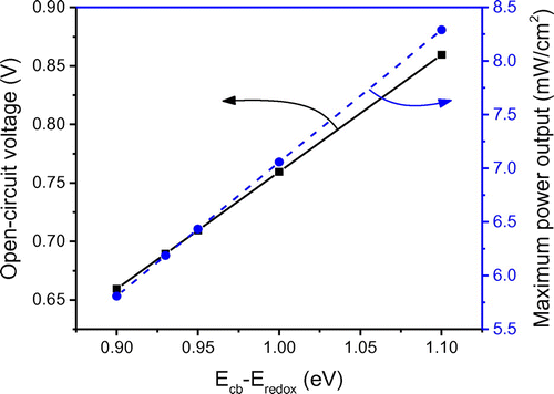
As mentioned above, the maximum attainable open-circuit voltage Voc generated in DSSCs can be determined by EF − ERedox. In this study, it was calculated to be 0.7 V under standard test conditions. Since EF is dependent on Ecb, one effective way to obtain a higher Voc is to increase the energy difference between conduction band edge (Ecb) and redox potential (Eredox). In the base case simulation, the value of Ecb − ERedox was assumed to be constant; however, in actual practice, it could vary due to the band edge shift. Influence of energy difference Ecb − ERedox on J–V characteristics is plotted in Figure . It could be seen that for the given short-circuit current (Jsc) and fill factor (FF), as Ecb − ERedox increases from 0.9 to 1.1 eV, there occurs an increase in Voc of similar magnitude from 0.66 to 0.86 V. Hence, it could be interpreted that the Ecb − ERedox has a dominant effect on the open-circuit voltage compared to the electron density (ne). Figure confirms that Voc and Ecb − ERedox have a linear relationship where as Ecb − ERedox difference increases (0.9–1.1 eV), the maximum power output linearly increases from 5.8 to 8.2 mW/cm2. This is due to the fact that, at given Jsc and FF, the maximum power output (Pmax) increases proportionally with Voc (). Therefore, it is critical to design DSSCs with a higher value of Ecb − ERedox to improve cell performance in terms of both open-circuit voltage and maximum power output. For given conduction band edge (Ecb), a higher Ecb − Eredox can be achieved through using alternative redox couples such as Co(II)/Co(III) (Yella et al., Citation2011) and Fe(CN)63−/4− (Daeneke et al., Citation2012), which have higher values of redox potential (Eredox). Recent research has proven that tuning the redox potential to match the oxidation potential of the sensitizer can minimize the energy loss in the dye regeneration step and thereby pave the way to attain a high open-circuit voltage approaching ~1 V (Yum et al., Citation2012).
Figure 10. The effect of the energy difference (Ecb − Eredox) on the J–V characteristics of the modeled DSSC.
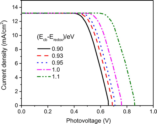
Figure 11. The effect of the energy difference (Ecb − Eredox) on the open-circuit voltage and maximum power output of the modeled DSSC.
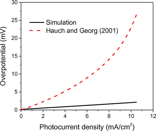
Yet another way to maximize the power output is to minimize the interfacial voltage loss. One of the main mechanisms that dictate the voltage loss is the overpotential that exits at the interface of electrolyte and counter electrode. The interfacial overpotential has two components: (i) diffusion overpotential and (ii) charge-transfer overpotential. Diffusion overpotential is generated due to diffusion limitations that occur in the electrolyte, while charge-transfer overpotential results from the fact that electrons have to pass through a solid-liquid phase boundary (Helmholtz layer). Both of these overpotentials are taken into account in the proposed model based on a generalized current-overpotential approach [Equation (25)], where the variation in surface concentrations are no longer negligible. The dependence of overpotential on the photocurrent density is plotted in Figure . As shown, the photocurrent influences the overpotential linearly. That is, as the photocurrent density increases from zero to the Jsc = 10.5 mA/cm2, there is an increase in the overpotential to 2.2 mV. The simulated results are in close agreement with the Butler-Volmer equation in which variation of redox couple concentration is negligible, which results in the low values of the overpotential. Hence, with an assumption that redox couple and
do not deviate much from open-circuit conditions, the concentrations of ion species can be approximated with their equilibrium values (
and
) which simplifies the Equation (25) to the following Butler-Volmer equation.
(39)
(39)
Figure 12. Comparison of the simulated results with theoretically predicted diffusion overpotential (Hauch & Georg, Citation2001).
For small overpotentials (), the Bulter-Volmer equation can be linearized.
(40)
(40)
The listed leading-order approximation indicates that the photocurrent has a linear relationship with overpotential.(41)
(41)
In general, the exchange current density (j0) is higher for an electrochemical reaction which is quicker and more reversible. The exchange current density can range from a very low value of 10−60 A/cm2 in a very slow and irreversible reaction to 10−1 A/cm2 in a fast and reversible reaction. The thermally produced Pt catalyst has exchange current density (j0) in a range of 0.05 − 0.35 A/cm2 (Papageorgiou, Maier, & Grätzel, Citation1997). In this study, 0.1 A/cm2 was adopted which corresponds to overpotential less than 5 mV at short-circuit condition. Such small overpotential is usually expected in the DSSCs, because they utilize highly efficient catalyst materials such as platinum and graphene nanoplatelets (CitationGong, Zhou, Sumathy, Yang, & Qiao, 2016). However, it is reported in the literature (Zheng et al., Citation2015) that for carbonaceous materials which are highly porous, the diffusion overpotential of redox couple through the pores may become a limiting factor. Due to the large excess of I− in the electrolyte, only the diffusion limits the current (Papageorgiou et al., Citation1996). Hence, the depletion of
at the counter electrode leads to the diffusion overpotential. Ideally, for a 2-nm thin layer Pt (Hauch & Georg, Citation2001; Vetter, Citation2013), the diffusion overpotential (ηD) is given as:
(42)
(42)
The diffusion-limiting current (Ilim) was measured to be . It can be seen from Figure that, as photocurrent density of Pt catalyst increases to 10.5 mA/cm2, the ηD increases of Pt catalyst exponentially from 0 to 26.5 mV which is one order of magnitude larger than the simulated results (2.2 mV). The discrepancy between diffusion overpotential and the simulated results of the current study can be attributed to the low limiting current (
) which reflects a diffusion controlled electrode reaction at the counter electrode surface. For platinum counter electrode, the short-circuit current density could reach up to 200 mA and hence a much lower ηD can be expected. It is worth noting that compared to the maximum attainable voltage (700 mV), the overpotential values are small and can be neglected for platinum catalyst based DSSCs.
5. Conclusion
A macroscopic, one-dimensional mathematical model of DSSCs has been presented. This model improved the simplified electrical model (CitationGong et al., 2016) through incorporating the interfacial charge transport phenomenon at TiO2/TCO and electrolyte/counter electrode contacts. Due to these improvements, the present model fitted the experimental J–V characteristics more accurately compared to the conventional diffusion model. The prediction accuracy was increased by adding an equivalent electrical circuit, which correlates internal resistance to sheet resistance and current leakage to shunt resistance. The calculated overall conversion efficiencies agree well with experimental results, which confirms the validity of the proposed model. The effect of important parameters such as series resistance, shunt resistance, Ecb − ERedox, and interfacial overpotential on J–V characteristics was simulated. The simulated results show a linear relationship between open-circuit voltage (Voc) and photoanode temperature (T) with a slope of −1 mV/°C, which is in agreement with published results. This bulk and interfacial model gives an insight into the relation between physical processes in DSSCs and overall cell performance. It can serve as an effective tool for studying various cell designs and operating parameters. Also, it can be tailored to simulate the performance of novel DSSCs using promising energy materials such as polymer electrolyte, and graphene-based counter electrode.
Additional information
Funding
Notes on contributors
Jiawei Gong
Jiawei Gong received his BE degree in Polymer Materials & Engineering at East China University of Science & Technology in 2010, MS and PhD degrees in Mechanical Engineering at North Dakota State University in 2013 and 2016, respectively. He is an active member of American Society of Mechanical Engineers. He has been the leading contributor to a significant number of research publications including top international journal papers, book chapters, and conference proceedings. He has also consistently served as an academic editor/reviewer in reputable journals. His research interests include solar photovoltaic and thermal technologies, energy nanomaterials, and photoelectrochemical cells for energy storage/conversion.
References
- Amiri, O., & Salavati-Niasari, M. (2015). High efficiency dye-sensitized solar cells (9.3%) by using a new compact layer: Decrease series resistance and increase shunt resistance. Materials Letters, 160, 24–27.10.1016/j.matlet.2015.07.077
- Bavarian, M., Nejati, S., Lau, K. K. S., Lee, D., & Soroush, M. (2013). Theoretical and experimental study of a dye-sensitized solar cell. Industrial & Engineering Chemistry Research, 53, 5234–5247.
- Belarbi, M., Benyoucef, B., Benyoucef, A., Benouaz, T., & Goumri-Said, S. (2015). Enhanced electrical model for dye-sensitized solar cell characterization. Solar Energy, 122, 700–711.10.1016/j.solener.2015.08.037
- Boschloo, G., & Hagfeldt, A. (2009). Characteristics of the iodide/triiodide redox mediator in dye-sensitized solar cells. Accounts of Chemical Research, 42, 1819–1826.
- Daeneke, T., Uemura, Y., Duffy, N. W., Mozer, A. J., Koumura, N., Bach, U., & Spiccia, L. (2012). Aqueous dye-sensitized solar cell electrolytes based on the ferricyanide-ferrocyanide redox couple. Advanced Materials, 24, 1222–1225.10.1002/adma.v24.9
- Ferber, J., Stangl, R., & Luther, J. (1998). An electrical model of the dye-sensitized solar cell. Solar Energy Materials and Solar Cells, 53, 29–54.10.1016/S0927-0248(98)00005-1
- Fredin, K., Ruhle, S., Grasso, C., & Hagfeldt, A. (2006). Studies of coupled charge transport in dye-sensitized solar cells using a numerical simulation tool. Solar Energy Materials and Solar Cells, 90, 1915–1927.10.1016/j.solmat.2005.12.004
- Gagliardi, A., Auf der Maur, M., Gentilini, D., & Di Carlo, A. (2009). Modeling of Dye sensitized solar cells using a finite element method. Journal of Computational Electronics, 8, 398–409.10.1007/s10825-009-0298-7
- Gagliardi, A., Auf der Maur, M., Gentilini, D., & Di Carlo, A. (2011a). Simulation of dye solar cells: Through and beyond one dimension. Journal of Computational Electronics, 10, 424–436.10.1007/s10825-011-0377-4
- Gagliardi, A., Auf der Maur, M. A., Di Carlo, A., & Carlo, A. D. (2011b). Theoretical investigation of a dye solar cell wrapped around an optical fiber. IEEE Journal of Quantum Electronics, 47, 1214–1221.10.1109/JQE.2011.2160843
- Gentilini, D., D’Ercole, D., Gagliardi, A., Brunetti, A., Reale, A., Brown, T., & Di Carlo, A. D. (2010). Analysis and simulation of incident photon to current efficiency in dye sensitized solar cells. Superlattices and Microstructures, 47, 192–196.10.1016/j.spmi.2009.10.005
- Giannuzzi, R., Manca, M., & Gigli, G. (2013). A new electrical model for the analysis of a partially shaded dye-sensitized solar cells module. Progress in Photovoltaics: Research and Applications, 21, 1520–1530.10.1002/pip.v21.7
- Gong, J., Qiao, H., Sigdel, S., Elbohy, H., Adhikari, N., Zhou, Z., … Qiao, Q. (2015). Characteristics of SnO2 nanofiber/TiO2 nanoparticle composite for dye-sensitized solar cells. AIP Advances, 5, 067134.10.1063/1.4922626
- Gong, J., Liang, J., & Sumathy, K. (2012). Review on dye-sensitized solar cells (DSSCs): Fundamental concepts and novel materials. Renewable and Sustainable Energy Reviews, 16, 5848–5860.10.1016/j.rser.2012.04.044
- Gong, J., & Sumathy, K. (2012, March 28–30). A theoretical study on third generation photovoltaic technology: Dye-sensitized solar cells. Proceedings of the International Conference on Renewable Energies and Power Quality (ICREPQ’12), Santiago de Compostela.
- Gong, J., Sumathy, K., Qiao, Q., & Zhou, Z. (2017). Review on dye-sensitized solar cells (DSSCs): Advanced techniques and research trends. Renewable and Sustainable Energy Reviews, 68, 234–246.10.1016/j.rser.2016.09.097
- Gong, J., Sumathy, K., & Liang, J. (2012). Polymer electrolyte based on polyethylene glycol for quasi-solid state dye sensitized solar cells. Renewable Energy, 39, 419–423.10.1016/j.renene.2011.07.015
- Gong, J., Sumathy, K., & Liang, J. (2016). A simplified electrical model of the dye-sensitised photoelectrochemical cell. International Journal of Sustainable Energy, 35, 75–87.
- Gong, J., Zhou, Z., Sumathy, K., Yang, H., & Qiao, Q. (2016). Activated graphene nanoplatelets as a counter electrode for dye-sensitized solar cells. Journal of Applied Physics, 119, 135501.10.1063/1.4945375
- Han, L., Koide, N., Chiba, Y., & Mitate, T. (2004). Modeling of an equivalent circuit for dye-sensitized solar cells. Applied Physics Letters, 84, 2433–2435.10.1063/1.1690495
- Hauch, A., & Georg, A. (2001). Diffusion in the electrolyte and charge-transfer reaction at the platinum electrode in dye-sensitized solar cells. Electrochimica Acta, 46, 3457–3466.10.1016/S0013-4686(01)00540-0
- Heo, J. H., Im, S. H., Noh, J. H., Mandal, T. N., Lim, C.-S., Chang, J. A., … Seok, S. (2013). Efficient inorganic–organic hybrid heterojunction solar cells containing perovskite compound and polymeric hole conductors. Nature Photonics, 7, 486–491.10.1038/nphoton.2013.80
- Huang, Y., Dai, S., Chen, S., Zhang, C., Sui, Y., Xiao, S., & Hu, L. H. (2009). Theoretical modeling of the series resistance effect on dye-sensitized solar cell performance. Applied Physics Letters, 95, 243503.10.1063/1.3270532
- Joshi, P. H., Korfiatis, D. P., Potamianou, S. F., & Thoma, K.-A. (2013). Optimum oxide thickness for dye-sensitized solar cells—effect of porosity and porous size. A numerical approach. Ionics, 19, 571–576.10.1007/s11581-012-0755-3
- Koide, N., Islam, A., Chiba, Y., & Han, L. (2006). Improvement of efficiency of dye-sensitized solar cells based on analysis of equivalent circuit. Journal of Photochemistry and Photobiology A: Chemistry, 182, 296–305.10.1016/j.jphotochem.2006.04.030
- Korfiatis, D. P., Potamianou, S. F., & Thoma, K.-A. (2008). Modeling of dye-sensitized titanium dioxide solar cells. Ionics, 14, 545–548.10.1007/s11581-008-0216-1
- Maçaira, J., Andrade, L., & Mendes, A. (2014). Modeling, simulation and design of dye sensitized solar cells. RSC Adv, 4, 2830–2844.10.1039/C3RA46295A
- Miettunen, K., Halme, J., Visuri, A.-M., & Lund, P. (2011). Two-dimensional time-dependent numerical modeling of edge effects in dye solar cells. The Journal of Physical Chemistry C, 115, 7019–7031.10.1021/jp110927j
- Murakoshi, K., Kano, G., Wada, Y., Yanagida, S., Miyazaki, H., Matsumoto, M., & Murasawa, S. (1995). Importance of binding states between photosensitizing molecules and the TiO2 surface for efficiency in a dye-sensitized solar cell. Journal of Electroanalytical Chemistry, 396, 27–34.10.1016/0022-0728(95)04185-Q
- Nazeeruddin, M. K., Kay, A., Rodicio, I., Humphry-Baker, R., Mueller, E., Liska, P., … Graetzel, M. (1993). Conversion of light to electricity by cis-X2bis(2,2’-bipyridyl-4,4’-dicarboxylate)ruthenium(II) charge-transfer sensitizers (X = Cl-, Br-, I-, CN-, and SCN-) on nanocrystalline TiO2 electrodes. Journal of the American Chemical Society, 115, 6382–6390.10.1021/ja00067a063
- Ni, M., Leung, M. K. H., Leung, D. Y. C., & Sumathy, K. (2006). Theoretical modeling of TiO2/TCO interfacial effect on dye-sensitized solar cell performance. Solar Energy Materials and Solar Cells, 90, 2000–2009.10.1016/j.solmat.2006.02.005
- Ni, M., Leung, M. K. H., & Leung, D. Y. C. (2008). Theoretical modelling of the electrode thickness effect on maximum power point of dye-sensitized solar cell. The Canadian Journal of Chemical Engineering, 86, 35–42.10.1002/(ISSN)1939-019X
- Noh, S. I., Ahn, H. J., & Riu, D. H. (2012). Photovoltaic property dependence of dye-sensitized solar cells on sheet resistance of FTO substrate deposited via spray pyrolysis. Ceramics International, 38, 3735–3739.10.1016/j.ceramint.2012.01.018
- Oda, T., Tanaka, S., & Hayase, S. (2006). Differences in characteristics of dye-sensitized solar cells containing acetonitrile and ionic liquid-based electrolytes studied using a novel model. Solar Energy Materials and Solar Cells, 90, 2696–2709.10.1016/j.solmat.2005.11.013
- Papageorgiou, N., Athanassov, Y., Armand, M., Bonho, P., Pettersson, H., Azam, A., & Grätzel, M. (1996). The performance and stability of ambient temperature molten salts for solar cell applications. Journal of The Electrochemical Society, 143, 3099–3108.10.1149/1.1837171
- Papageorgiou, N., Maier, W. F., & Grätzel, M. (1997). An iodine/triiodide reduction electrocatalyst for aqueous and organic media. Journal of The Electrochemical Society, 144, 876–884.10.1149/1.1837502
- Press, W. H., & Teukolsky, S. A. (2007). Numerical recipes: The art of scientific computing (3rd ed.). Cambridge: Cambridge University Press.
- Rock, S. E., Shi, X., Garland, J. E., & Roy, D. (2014). Experimental considerations for temperature controlled measurements of fast charge recombination times in dye sensitized solar cells using open circuit voltage decay and impedance spectroscopy. Measurement, 53, 71–82.10.1016/j.measurement.2014.03.012
- Sigdel, S., Elbohy, H., Gong, J., Adhikari, N., Sumathy, K., Qiao, H., … Qiao, Q. (2015). Dye-sensitized solar cells based on porous hollow tin oxide nanofibers. IEEE Transactions on Electron Devices, 62, 2027–2032.10.1109/TED.2015.2421475
- Soedergren, S., Hagfeldt, A., Olsson, J., & Lindquist, S.-E. (1994). Theoretical models for the action spectrum and the current-voltage characteristics of microporous semiconductor films in photoelectrochemical cells. The Journal of Physical Chemistry, 98, 5552–5556.10.1021/j100072a023
- Usami, A., Seki, S., Mita, Y., Kobayashi, H., Miyashiro, H., & Terada, N. (2009). Temperature dependence of open-circuit voltage in dye-sensitized solar cells. Solar Energy Materials and Solar Cells, 93, 840–842.10.1016/j.solmat.2008.09.040
- Vetter, K. J. (2013). Elektrochemische Kinetik. New York, NY: Springer-Verlag.
- Yella, A., Lee, H.-W., Tsao, H. N., Yi, C., Chandiran, A. K., Nazeeruddin, M. K., … Gratzel, M. (2011). Porphyrin-sensitized solar cells with cobalt (II/III)-based redox electrolyte exceed 12 percent efficiency. Science, 334, 629–634.10.1126/science.1209688
- Yum, J.-H., Baranoff, E., Kessler, F., Moehl, T., Ahmad, S., Bessho, T., … Grätzel, M. (2012). A cobalt complex redox shuttle for dye-sensitized solar cells with high open-circuit potentials. Nature Communications, 3, 631.doi:10.1038/ncomms1655
- Zheng, M., Huo, J., Tu, Y., Wu, J., Hu, L., & Dai, S. (2015). Flowerlike molybdenum sulfide/multi-walled carbon nanotube hybrid as Pt-free counter electrode used in dye-sensitized solar cells. Electrochimica Acta, 173, 252–259.10.1016/j.electacta.2015.05.069
- Zhou, Z., Sigdel, S., Gong, J., Vaagensmith, B., Elbohy, H., Yang, H., … Qiao, Q. (2016). Graphene-beaded carbon nanofibers with incorporated Ni nanoparticles as efficient counter-electrode for dye-sensitized solar cells. Nano Energy, 22, 558–563.10.1016/j.nanoen.2016.03.003

