 ?Mathematical formulae have been encoded as MathML and are displayed in this HTML version using MathJax in order to improve their display. Uncheck the box to turn MathJax off. This feature requires Javascript. Click on a formula to zoom.
Abstract
Digital signal processing (DSP) circuits are extremely important in computing and communications areas. One application of DSP is a Finite impulse response (FIR) filter. The principle objective of this exploration is to present a methodology for an upgraded framework of a FIR digital filter from software level to the hardware level. It includes the selection of design method, structure and cost effective hardware utilization. Theoretical and experimental results performed FIR band pass filter suggests that the window design method is relatively simple and easy to use because of the availability of well-defined equation. Comparison presented that Kaiser window gives the minimum main-lobe width and a sharp cut-off which means this window has less transition width and the study showed that the Direct-Form structure approach is simpler and offers a better performance than other common filter structures. It results in low cost, reduced area and more robust to withstand the quantization errors. For efficient hardware realization, the paper investigates the impacts of quantization on frequency response by progressively diminishing the quantity of bits in every coefficient using an iterative algorithm to a level where its frequency response matches to the novel requirements. Experimental study of coefficient quantization uncovers a connection between the quantity of bits, number of coefficients and the frequency response that consequence in reduced area and better speed. The synthesis results show that the discussed technique can substantial help in lessening the equipment assets. Computer aided design (CAD) tools are used to implement the design by adopting the behavioural level design method.
Public Interest Statement
Digital filters are incredibly powerful, but easy to use. In fact, this is one of the main reasons that digital signal processing DSP has become so popular it offers number of advantages over analog signal processing (ASP). Well ideally the application is defined for the signal you are trying to process. It can be anything from audio, video, sensor output, data from the web, in short and simple words any sort of information. So, processing it means making the information understandable.
1. Digital filter
A digital filter is a system that performs mathematical operations on a sampled, digitized signal to reduce or enhance certain features of the processed signal. Digital filter scheme consists of a pre-filter or anti-aliasing filter to perform filtering of an input signal using a low pass filter. This is required to restrict the bandwidth of a signal to satisfy the sampling theorem. An interface is needed between the analog signal and the digital filter, this interface is known as analog-to-digital converter (ADC). After the process of sampling and converting, a digital signal is ready for further processing using an appropriate digital signal processor. The output signal that is digitized is usually changed back into analog form using digital-to-analog converter (DAC). The digital filtering process is shown in Figure (Alam & Gustafsson, Citation2014).
Digital filter is a major topic in the field of digital signal processing (DSP). Over the past few years the field of DSP has become so popular both technologically and theoretically. The major reason for its success in the industry is due to the use of the low cost and development of software and hardware. Applications of DSP are mainly the algorithms that are implemented either in software using interactive software like MATLAB or a processor. In high-bandwidth applications FPGA, ASIC or a specialized digital signal processor are used for expediting operations of filtering. Digital filters are preferably used because they eliminate several problems associated with analog filters. There are two fundamental types of digital filters: Finite Impulse Response (FIR) and Infinite Impulse Response (IIR) (Tian, Li, & Li, Citation2013).
2. FIR filters
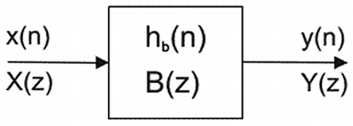
FIR filters also known as non-recursive digital filters have a finite impulse response because after a finite time the response of FIR filter settles to zero. Block diagram of FIR filter is shown in Figure .
The basic structure of FIR filter consists of adders, multipliers and delay elements as shown in Figure .
The difference equation of nth order digital filter (FIR) can be represented as:
The transfer function H(z) is given as:
where X(z) is the filter’s input and Y(z) is the filter’s output. In realization, a given transfer function is used to convert into a suitable filter structure (Xu, Yin, Qin, & Zou, Citation2013).
The main advantages of the FIR filter design over their IIR equivalents are the following:
| (1) | FIR filters with exactly linear phase can easily be designed. | ||||
| (2) | There exist computationally efficient realizations for implementing FIR filters. | ||||
| (3) | FIR filters realized non-recursively are inherently stable and free of limit cycle oscillations when implemented on a finite-word length digital system. | ||||
| (4) | Excellent design methods are available for various kinds of FIR filters with arbitrary specifications. | ||||
| (5) | Design and noise issues are less complex than IIR filter (Rabiner, Kaiser, Herrmann, & Dolan, Citation1974). | ||||
3. Design stages of digital filters
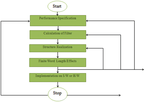
Design of a digital filter involves the following five steps:
| (1) | Filter specification | ||||
| (2) | Filter coefficient calculation | ||||
| (3) | Realization | ||||
| (4) | Analysis of finite word length effect and | ||||
| (5) | Implementation | ||||
These five stages are interlinked as shown in Figure .
In first stage the required specifications of the FIR filter are defined. Whereas, in second stage window method is selected because it offers a simple and flexible way of calculating the FIR filter coefficient; due to its well-defined equations.
4. Filter designing
Filter designing and analysis tool (FDATool) is used for designing the digital filters. It is a powerful user interface for scheming and analyzing the filter’s behavior quickly in signal processing. It is used to realize quantized direct-form FIR filters Simulink model (Siauw & Bayen, Citation2014).
To analyze the behavior of FIR digital filter, different window functions are used by using the specifications as shown in Table .
Table 1. Filter specifications
Magnitude and phase responses of a 15th order digital band pass filter using Hanning, Hamming, Blackman and Kaiser window functions are observed and investigated as shown in Figures – (Jieshan & Shizhen, Citation2009).
Table shows the brief comparison among different window functions that are used in designing.
Table 2. Comparison of 15th-order fir BPF using different window functions
Using the above comparison, it is analyzed that the Kaiser window is more reliable and result in high gain. Generally, the width of the main-lobe determines the transition bandwidth, while the relative heights of the side-lobes control the size of the ripples in the amplitude response. There is a bargain between main-lobe width and a height of side-lobe; in other words, both quantities cannot be reduced at the same time. Calculations show that the Kaiser window gives the minimum normalized transition width of main-lobe i.e. 0.11719 and a sharp cutoff which means this window has less transition width and introduces more ripple. This window gives simple and fast results (Patel, Kumar, Jaiswal, & Saxena, Citation2013).
5. Hardware realization
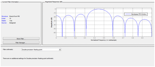
As the focus of this research work is to minimize the hardware implementation cost. For this, the effects of quantization by varying the number of quantization bits and analyzing the corresponding frequency responses are observed (Mehboob, Khan, & Qamar, Citation2009). A 15th-order band pass filter using Kaiser window is realized as double precision floating point implementation (see Figure ) converted to a quantized filter. Float-to-fixed point conversion is required to target ASIC and fixed-point digital signal processor core which will lessen the truncation and calculation complexity.
The number of quantization bits are reduced from 16–3 using an iterative algorithm and keeping the frequency response exactly within limits. The frequency response of the filter without quantization is shown in Figure .
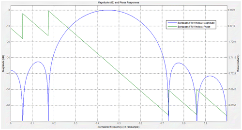
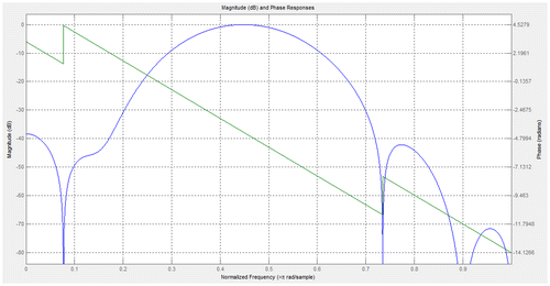
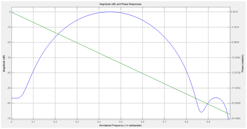
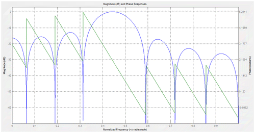
For low area requirement coefficients of a filter are converted to a fixed point numeric representation by quantizing at [16, 15], [8, 7], [6, 5] and [3, 2]. Where the numbers 16, 8, 6, and 3 shows the input word length or quantizing bits and the numbers 15, 7, 5, and 2 depicts the input fraction length. Quantized frequency response plots of FIR band pass filter are shown from Figures – (Beyrouthy & Fesquet, Citation2011).
It is observed that even if the number of bits reduced to less than half of the original 16 bits, the resulting filter response has no significant change. By doing further analysis, more reduction in the quantization bits still produces no detectable deteriorating effect in the pass band, but the damage start begins in stop band attenuation and the transition band width of the filter’s frequency response (Table ).
Table 3. Performance characteristics of filters
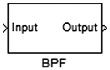
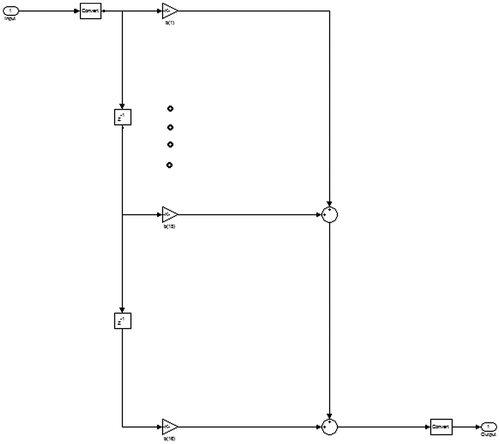
The asset use regarding essential (Gates) components utilized is observed to be least for the proposed BPF3. The filter with the most favorable number of quantized bits is then converted to VHDL. The Simulink model of a designed filter is shown in Figure .
Coefficients of a direct-form band pass FIR filter are shown in Figure .
Designing of a filter is done using a Hardware Description Language (HDL) code. Following tools are used for the implementation of BPF (Navaid, Raaziyah, Rajesh, & Sandeep, Citation2013):
| - | ModelSim 6.5b for simulation. | ||||
| - | Leonardo Spectrum Level 3 for synthesis. | ||||
| - | Mentor’s Pyxis Custom IC Design Platform is used for design capture to schematic-driven layout. | ||||
The custom integrated circuit or ASIC design flow chart is shown in Figure .
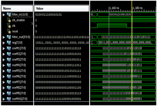
HDLs offer advantages in designing the complex circuits using the top down approach and one can verify the functionality of the design early (Nekoei, Kavian, & Strobel, Citation2010). Behavioral level simulation of BPF is shown in Figure .
After verifying the behavior, the filter’s VHDL code is synthesized into a gate level netlist and represents a new structural VHDL schematic (Fuller, Citation2007). The Leonardo Spectrum Level 3 is used to generate the filter top module as shown in Figure .
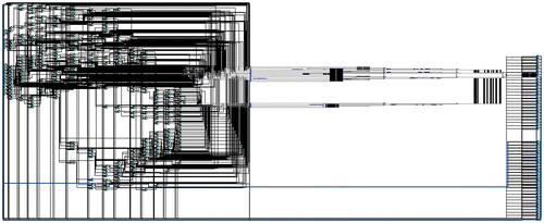
The technology TSMC 0.35 μ is selected to generate the RTL schematic that can be viewed as a gate-level schematic. The complete RTL schematic of a BPF is shown in Figure .
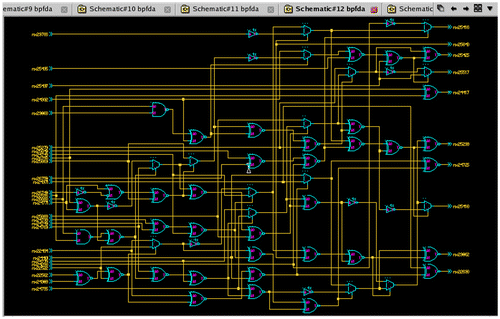
The Leonardo Spectrum is used to provide a Technology schematic that can be viewed as an architecture-specific schematic. This schematic is generated after targeting the technology in the synthesis process. It shows the design in terms of logic elements optimized to the target device or technology. The view technology schematic of the designed filter is shown in Figure .
The Mentor’s Pyxis IC platform simulation is performed and shown in Figure .
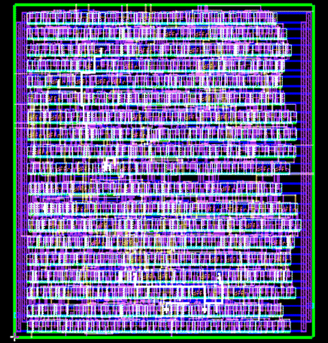
The Pyxis Layout provides a fast and flexible environment. An automated layout generated after performing the function of floor planning and the function of placing and routing is shown in Figure .
6. Conclusion
FIR filters are extensively used in wired, wireless communications, video, audio processing and handheld devices are preferred because of their stability and linear phase properties. This paper presents a novel design methodology for an optimized FIR digital filters from software level to the hardware level. The main goal is to encompass all the fields that are used in the efficient hardware realization of filters i.e. design method, selection of structure and the algorithm to reduce the arithmetic complexity of FIR filtering.
Theoretical and experimental result suggests that the Kaiser window gives the minimum main-lobe width i.e. 0.11719 and a sharp cutoff which means this window has less transition width, and the study showed that the direct-form structure approach is simpler, more robust to withstand the quantization errors, low cost and offers better performance than other common structures. Proposed optimized filter implementation using an appropriate quantization scheme results in reducing arithmetic complexity, area and hardware resources. Comparison revealed that the optimized filter implementation is requiring 42% less hardware resources than the normal filter implementation.
Funding
The authors received no direct funding for this research.
Acknowledgements
I would like to express gratitude to the National Institute of Electronics (NIE) and their team including Sir Shahid Ahmed Khan (Incharge IC Design Center) and special thanks to Sir Kamran Bhatti (Senior Research Officer) for providing unconditional support and technical knowledge that made possible to complete this research work in smooth way.
Supplemental_material.docx
Download MS Word (1.2 MB)Additional information
Notes on contributors
Sumbal Zahoor
Sumbal Zahoor is doing PhD in Electrical and Electronic Engineering from the University of Lahore. After completing her BSc in Electrical Engineering, her interest took her into university of the Punjab, where she completed her MSc in Microelectronics Engineering by securing 2nd position. She has been working with engineering universities for more than five years till to date. Her research interests include signal processing, VLSI and image processing.
References
- Alam, S. A., & Gustafsson, O. (2014). Design of finite word length linear-phase FIR filters in the logarithmic number system domain. VLSI Design, 2014, 1–14.10.1155/2014/217495
- Beyrouthy, T., & Fesquet, L. (2011). An event-driven FIR filter: Design and implementation. In Proceeding 22nd IEEE International Symposium on Rapid System Prototyping (RSP) (pp. 59–65).10.1109/RSP.2011.5929976
- Dr., Fuller, L. (2007). Mentor graphics tools tutorial. Rochester: Rochester Institute of Technology Microelectronic Engineering.
- Jieshan, L., & Shizhen, H. (2009). An design of the 16-order FIR digital filter based on FPGA. In Proceedings international conference on information science and engineering (ICISE), IEEE (pp. 489–492).
- Mehboob, R., Khan, S. A., & Qamar, R. (2009). FIR filter design methodology for hardware optimized implementation. IEEE Transactions on Consumer Electronics, 55, 1669–1673.10.1109/TCE.2009.5278041
- Navaid, Z., Raaziyah, R., Rajesh, M., & Sandeep, S. (2013). High speed reconfgurable FPGA based digital flter. In book: quality, reliability, security and robustness in heterogeneous networks (pp. 470–478).
- Nekoei, F., Kavian, Y. S., & Strobel, O. (2010). Some schemes of realization digital FIR filter on FPGA for communication application. In Proceeding 20th international crimean conference on microwave and telecommunication technology (pp. 616–619).
- Patel, R., Kumar, M.Jaiswal, A. K., & Saxena, R. (2013). Design technique of bandpass FIR filter using various window function. IOSR Journal of Electronics and Communication Engineering, 6, 52–57.10.9790/2834
- Rabiner, L. R., Kaiser, J. F., Herrmann, O., & Dolan, M. T. (1974). Some comparisons between FIR and IIR digital filters. Bell System Technical Journal, 53, 305–331.10.1002/bltj.1974.53.issue-2
- Siauw, T., & Bayen, A. (2014). An introduction to MATLAB programming and numerical methods for engineers. Cambridge, MA: Academic Press.
- Tian, J., Li, G., & Li, Q. (2013). Hardware-efficient parallel structures for linear-phase FIR digital filter. In Proceedings of 56th IEEE international midwest symposium on circuits and systems (MWSCAS 2013) (pp. 995–998).10.1109/MWSCAS.2013.6674819
- Xu, C., Yin, S., Qin, Y., & Zou, H. (2013). A novel hardware efficient FIR filter for wireless sensor networks. In Proceedings of Fifth IEEE international conference on ubiquitous and future networks (ICUFN 2013) (pp. 197–201).



![Figure 10. BPF 1 (Quantization [16, 15] of FIR band pass filter).](/cms/asset/9bd4ee19-fbe9-4028-a9ce-192c19c08432/oaen_a_1323373_f0010_oc.gif)
![Figure 11. BPF 2 (Quantization [8, 7] of FIR band pass filter).](/cms/asset/1d42277d-94ef-4794-8085-5c794b300676/oaen_a_1323373_f0011_oc.gif)
![Figure 12. BPF 3 (Quantization [6, 5] of FIR band pass filter).](/cms/asset/5b5185e0-d4cd-45d2-8dec-02ca7a16cb97/oaen_a_1323373_f0012_oc.gif)
![Figure 13. BPF 4 (Quantization [3, 2] of FIR band pass filter).](/cms/asset/5ade4964-7378-41ca-ac08-502c205eff54/oaen_a_1323373_f0013_oc.gif)
