 ?Mathematical formulae have been encoded as MathML and are displayed in this HTML version using MathJax in order to improve their display. Uncheck the box to turn MathJax off. This feature requires Javascript. Click on a formula to zoom.
Abstract
A documented poundo yam process plant that produces 12.25 kg of poundo yam within 315.04 min was studied so as to address its associated problems. It was found that its production capacity is limited due to process time delay of 77 and 216 min experienced at the parboiling and drying section respectively. This informed the need to design a dynamic facility layout to increase production capacity, introduce flexibility of material flow through the process plant and manage effectively material flow through the process plant. In order to achieve this, a software called poundosim was developed using necessary design model equations and data. This will assist in forecasting material flow above the static reference frame of the production facility, and iteratively generate the optimal machine configuration within cost constraint, thereby preventing unending increase of service points at the regions of bottlenecks and ensuring economic viability of the entire processing plant. The successful deployment of the developed poundosim using input of values within the range of 12.25–134.75 kg at an increment of 12.25 kg shows a considerable decrease in the total process time at optimal machine configuration compared with the initial reference machine configuration. Thus, the developed model does prove useful for process plant which has similar attributes with poundo yam flour processing plant as it takes machine configuration matrix and the economic implication of production capacity into consideration.
Public Interest Statement
Based on some generic model for dynamic layout facility of poundo yam flour processing plant, a software called poundosim was developed to sort out necessary design equations and data of an existing static layout to increase the production volume at optimal production time. The existing model and design equations do address the limitations in the static layout of the poundo yam flour processing plant by increasing the throughput capacity, permitting flexibility of material flow and effective utilization of resources. The developed software does prove useful for processing plant with similar attributes to poundo yam flour processing plant because it takes the machine configuration matrix and the economic implication of production capacity into context. The package developed can assist and guide prospective investors in knowing the amount of capital needed to invest with and what would be the profit outcome at the end of any targeted period of time under a ceteris paribus condition.
1. Introduction
Facility layout entails the optimum arrangement and allocation of available resources such as space, personnel, storage space etc. to facilitate effectiveness in production process (Subodh & Kuber, Citation2014). A properly arranged facility improves operating efficiency which has justified the need to formulate facility layout problem with the intent to solve industrial challenges. However, the problems to be solved are diverse in works of literature ranging from material handling problems, space allocation of machines and facilities within plant site etc. With dynamic/static layout problem being the most encountered problem (Amine, Henri, & Sonia, Citation2007). Dynamic layout is designed to respond to series of changes often dictated by market and product demand; consequently making the layout relevant over periods demarcated in weeks, months or years (Alan & Shang, Citation2004; Amine et al., Citation2007). The essence of dynamic facility layout as opposed to static facility layout is to replace the cost of rearrangement with the cost of reconstruction which is inherent in static facility layout. Dynamic facility layout is a layout that permits the rearrangement of production facility to respond to product changes and product mix; dynamic facility layout can be attributed to static facility layout rearrangement to respond market changes demarcated over periods which could be in weeks, months or years (Alan & Shang, Citation2004; Amine et al., Citation2007; Balakrishnan, Cheng, Conway, & Lau, Citation2003; Kusiak & Heragu, Citation1987). Static layout problem which is also facility layout problem is formulated as Quadratic Algorithm Problem (Koopmans & Beckmann, Citation1957); the changes brought about by flow through the facility layout permits the static layout problem to be modeled as dynamic layout problem. Factors associated with the changes in flow are product design change, product addition or removal, production equipment replacement, short product life cycle, production volume change and associated changes in schedule (Heragu, Citation1992). Metaheuristics approach such as genetic algorithm, tabu search, simulated annealing and other hybrid metaheuristic approach are the solution methods employed in solving dynamic layout problem as evident in the works of Balakrishnan and Cheng (Citation2000), Baykasoğlu and Gindy (Citation2001), Bos (Citation1993), Kaku and Mazzola (Citation1997), McKendall and Shang (Citation2006a, Citation2006b), Wu, Chung, and Chang(Citation2008) and Balakrishnan et al. (Citation2003). The poundo yam flour processing plant layout is a static layout constituting the yam selection and weighing, washing, peeling and slicing, parboiling, drying, sieving and packaging sections and having the capacity to process 50.25 kg of yam tubers to 12.25 kg of poundo yam per throughput production (Ayodeji, Olabanji, & Adeyeri, Citation2012) and subsequent automation of the process plant (Ayodeji, Khubulani, Oduetse, & Mohammed, Citation2015) which reduced the processing time from 6 h 12 min to 5 h 19 min. Prior to the dynamic layout model for poundo yam flour processing plant (Ogunsua, Citation2016), the existing static layout does not permit flexible rearrangement of machines, hence modelling the system as a quadratic algorithm problem which is a complex combinatorial problem does not suffice. The modelling of dynamic facility layout to; introduce some measure of flexibility at the regions of bottleneck, ensure effectiveness in the material handling, increase the per throughput production at optimal production time; and some sets of design equations to optimally populate the dynamic layout model at optimal production time consequently ensuring economic viability of the entire process plant by preventing redundancy at the region of bottleneck in the system (the parboiling and drying sections) constitute the latest improvements on the processing plant (Ogunsua, Citation2016). In view to sequentially arrange and implement the design equations to optimally populate the dynamic layout model for the existing processing plant, a dynamic programming software called Poundosim was developed with the intent to the sort out necessary design equations and data, to forecast material flow above the static reference frame of the production facility, and iteratively generate the optimal machine configuration within cost constraint consequently preventing unending increase of service points at the regions of bottlenecks and ensuring economic viability of the entire processing plant.
2. Methodology
2.1. Dynamic programming design
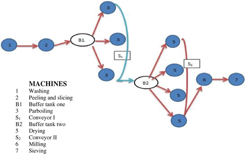
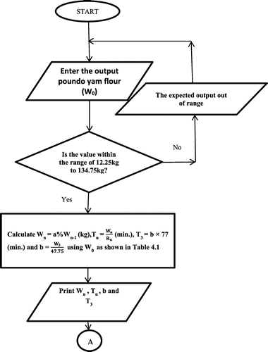
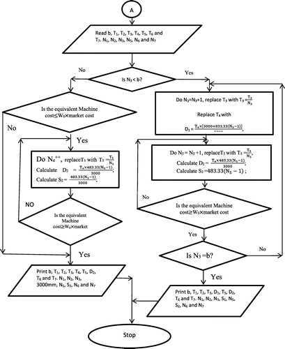
Using Equations (1)–(9) and model formulation in Tables and by Ogunsua (Citation2016), flowcharts were designed to generate the material flow through the process plant, generate the optimal machine configuration and forecast process time at reference and optimal machine configurations as shown in Figures and . The flowcharts were used to create software (Poundosim) in java programming language. The Governing Design Equation constitute following in view to populate the dynamic facility model as shown in Figure : the material handling equation which extends the length of conveyor I and the introduced conveyor II as stated in Equations (1) and (2); the objective function equation which forecast the process time at each of the units in the process plant as stated in Equations (3)–(5); the cost constraint equations which prevents unending increase of the service points at the region of bottlenecks specifically at the parboiling and drying section as shown in Equations (6)–(8); and the weight constraint equation which prevents redundancy in the system specifically at the parboiling section as shown in Equation (9).(1)
(1)
(2)
(2)
Table 1. Machine process time at reference machine configuration
Table 2. Machine process time at optimal machine configuration
S1 represents the length of conveyor I; S2 represents the length of conveyor II; L3 represents the extra length of the conveyor I per number of parboiler (833.33 mm/parboiler) when N3 > 1 (Ajamu, Citation2014); L5 represents the introduced length of the conveyor II per number of dryers (483.33 mm/dryer) when N5 > 1 (Afolami, Citation2014).(3)
(3)
(4)
(4)
(5)
(5)
where T represents the total process time per throughput.
T1, T2, T3, T5, T6 and T7 represents the process time of the washing, peeling and slicing, parboiling, drying, milling and sieving machines respectively.
N1, N2, N3, N5, N6 and N7 represents the number of washing, peeling and slicing, parboiling, and drying.
D1 represents the time of material transport through conveyor I at the parboiler.
D2 represents the time of material transport through conveyor II at the dryer.(6)
(6)
(7)
(7)
where C1, C2, C3, C4, C5, C6 and C7 represent the equivalent cost per throughput of the washing, peeling and slicing, parboiling, conveyor, drying, milling and sieving machines respectively.
N1, N2, N3, N5, N6 and N7 is the number of washing, peeling and slicing, parboiling, conveyor, drying, milling and sieving machine respectively.
W0 represents the weight of poundo yam flour produced per throughput = 12.25 kg/throughput (Ayodeji et al., Citation2015).
L3 is the extra length of conveyor per parboiler to convey materials from the parboiling machine when N3 ˃ 1.
L5 is the extra length of conveyor per dryer to convey dried chips of yam when the number of drying machine N5 ˃ 1.(8)
(8)
Ni = 648 throughputs to breakeven (Ogunsua, Citation2016).
Where Cn is the cost constraint of machine-n.
Tn is the process time per throughput of machine-n.
T is the total process time per throughput of the entire process plant.
FCn is the fixed cost of machine-n taking inflation rate into consideration from 2014 to 2016.
K is the constant fixed cost of the control system and the contingencies.
(9)
(9)
where N3 is the number of parboiling machine in the process plant.
W3 is the weight input into the machine at location 3 in the process plant (Parboiling machine).
b is the number of throughput approximated to the nearest whole number.
3. Result and discussion
3.1. Reference machine configuration flowchart
The Reference Machine Configuration Flowchart as shown in Figure takes the input (W0) which is expected poundo yam flour to be produced from the process plant. It uses the formulated model equations in Table to estimate the weight of material flow through the machines in the process plant and forecast the process time at reference machine configuration.
3.2. Optimal machine configuration flowchart
The Optimal Machine Configuration Flowchart generates the optimal machine configuration for a specified throughput capacity. It increases the service points at the region of bottlenecks; the parboiling and the drying section. The product of the market cost per throughput production and the specified weight (W0) of poundo yam flour expected from the process plant is set as a constraint for the machine cost contribution as shown in Figure for the drying machine while the weight is set as constraint for the number of parboiling machine using the number of throughput (b) as stated in Equation (9).
3.2.1. Equivalent machine cost contribution
The Machine Cost Contribution per throughput is as stated in Equation (10) using Equations (6)–(8). The detailed estimate is as shown in Tables and (Ogunsua, Citation2016).(10)
(10)
Table 3. Machine energy cost per throughput
Table 4. Equivalent machine cost contribution per throughput (Cn)
3.3. Dynamic programming result
The software developed (Poundosim) was tested with values within the range of 12.25–134.75 kg of poundo yam flour per throughput capacity at an increment of 12.25 kg. The machine processing time for each of the machines in the process plant as generated by the software at specified ranges of input at reference and optimal machine configurations are as shown Table . At reference machine configuration when number of parboiling (N3) and drying machine (N5) is one as shown in Table , the length of the conveyor I (S1) and conveyor II (S2) remains at 3,000 and 0 mm respectively in line with the process plant design (Ayodeji et al., Citation2012); an indication that while the parboiling and drying machine is one, there is no need for the extension of conveyor I length and the introduction of conveyor II. However, with the increment in the number of parboiling and drying machine, the length of conveyor I increase to accommodate the increasing number of parboiling machine while there was introduction of conveyor II and an increase in the length of the conveyor with increasing number of drying machines. There was also a significant reduction in the process time when the total process time at optimal machine configuration was compared with the total process time at reference machine configuration for specified throughput capacity as shown in Table .
Table 5. Reference and optimal machine configuration and corresponding machine process time
Where T1, T2, T3, D1, T5, T6, D2 and T7 represents the process time of the washing, peeling and slicing, parboiling, conveyor 1, drying, milling, introduced conveyor 2 and sieving machines respectively.
N1, N2, N3, N5, N6 and N7 represents the number of washing, peeling and slicing, parboiling, drying.
S1 and S2 represents the length of conveyor I at the parboiling machine and introduced conveyor II at the drying machine.
3.4. The Poundosim software
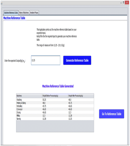
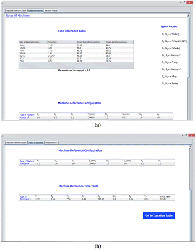
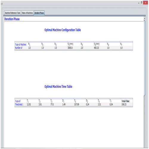
The interface displaying the reference machine configuration and process time, optimal machine configuration and process time result for the developed software is as shown in Plates , and . In line with the design of the flowcharts in Figure , the software generates the material flow through the process plant using model formulation Table . Upon the input of the expected poundo yam flour output (W0) within the range 12.25–134.75 kg as shown in Plate , the Generate Reference Table button generates the material flow through the process plant; subsequently, the Go To Reference Table button switches the top menu from Machine Reference Table icon to the Rate of Machines icon in which the Machine Reference Table displays the material flow through the process plant, the machine ratings and the reference machine configuration and corresponding process time is as shown in Plate . On the Machine reference table icon, the Go To Iteration button executes the programming command for the dynamic programming design of the flow chart in Figure to generate the optimal machine configuration at initial specified input (W0) and switches the icon menu from Rate of Machine to Iteration Phase where the optimal machine configuration and the corresponding process time is displayed as shown in Plate .
4. Conclusion
The developed poundosim software was able to sort out the necessary data, forecast material flow through the processing plant and implement the design equations to optimally populate the existing dynamic layout model. At inputs within the range of 12.25–134.75 kg poundo yam flour at an increment of 12.25 kg, the software generated optimal machine configuration with a considerable reduction in total processing time compared with the reference machine configuration at equivalent throughput capacity consequently bringing the machine configuration matrix and the economic viability of the processing plant into context. Although the software is tailored to poundo yam flour processing plant, the software application could be broadened to handle other processing plant with similar attributes.
Additional information
Funding
Notes on contributors
M.K. Adeyeri
Our research team is involved in all forms of need-driven manufacturing activities ranging from agrarian products processing to human mobility support systems. Our research aims to improve manufacturing systems or products and processes via the use of innovative technology or concept. The team incorporates automated and sophisticated computerized design and operational systems in its manufacturing works. Similarly, our core research focus also entails the area of human performance enhancement in both cognitive and physical domains. The team employs classical and experimental ergonomics, cognitive and physiological Engineering, and application of new technologies in achieving defined manufacturing goals.
The group’s aims and expertise are hinged on wide spectrum of manufacturing research. The team has key expertise in the following areas: design and fabrication of process plants; intelligent automation and assembly; metal forming; welding technologies; applied ergonomics; modelling and systems design; industrial systems maintenance and sustainability technologies; and production and manufacturing system.
References
- Afolami, K. A. (2014). Development and performance evaluation of washing, peeling and parboiling machines for a poundo yam flour process plant (Unpublished ME thesis). Department of Mechanical Engineering, Federal University of Technology, Akure.
- Ajamu, T. A. (2014). Development and performance evaluation of drying, milling and sieving machines for a poundo yam flour process plant. (Unpublished ME thesis). Department of Mechanical Engineering, Federal University of Technology, Akure.
- Alan, R. M. J., & Shang, J. (2004). Hybrid ant systems for the dynamic facility layout problem. Computers & Operations Research, 33, 790–803.
- Amine, D., Henri, P., & Sonia, H. (2007). Facility layout problems: A survey. Annual Reviews in Control, 31, 255–267.
- Ayodeji, S. P., Khubulani, M., Oduetse, M., & Mohammed, O. O. (2015). A control system for a poundo yam flour processing plant. African Journal of Science, Technology, Innovation and Development, 7, 192–200.10.1080/20421338.2015.1040285
- Ayodeji, S. P., Olabanji, O. M., & Adeyeri, M. K. (2012). Design of a process plant for the production of poundo yam. International Journal of Engineering (IJE), 6, 10–24.
- Balakrishnan, J., & Cheng, C. H. (2000). Genetic search and the dynamic layout problem. Computers and Operations Research, 27, 587–593.10.1016/S0305-0548(99)00052-0
- Balakrishnan, J., Cheng, C. H., Conway, D. G., & Lau, C. M. (2003). A hybrid genetic algorithm for the dynamic plant layout problem. International Journal of Production Economics, 86, 107–120.10.1016/S0925-5273(03)00027-6
- Baykasoğlu, A., & Gindy, N. N. Z. (2001). A simulated annealing algorithm for dynamic layout problem. Computers and Operations Research, 28, 1403–1426.10.1016/S0305-0548(00)00049-6
- Bos, J. (1993). Zoning in forest management a quadratic assignment problem solved by simulated annealing. Journal of Environmental Management, 37, 127–145.
- Heragu, S. (1992). Recent models and techniques for solving the layout problem. European Journal of Operational Research, 57, 136–144.10.1016/0377-2217(92)90038-B
- Kaku, B., & Mazzola, J. B. (1997). A Tabu-search heuristic for the Plant Layout Problem. INFORMS Journal on Computing, 9, 374–384.10.1287/ijoc.9.4.374
- Koopmans, T. C., & Beckmann, M. (1957). Assignment problems and the location of economic activities. Econometrica, 25, 53–76.10.2307/1907742
- Kusiak, A., & Heragu, S. S. (1987). The facility layout problem. European Journal of Operational Research, 29, 229–251.10.1016/0377-2217(87)90238-4
- McKendall Jr., A. R., & Shang, J. (2006a). Hybrid ant systems for the dynamic facility layout problem. Computers and Operations Research, 33, 790–803.10.1016/j.cor.2004.08.008
- McKendall Jr., A. R., & Shang, J. (2006b). Simulated annealing heuristics for the dynamic facility layout problem. Computers and Operations Research, 33, 2431–2444.10.1016/j.cor.2005.02.021
- Ogunsua, A. (2016). Design of dynamic facility layout and virtual monitoring system for poundo yam flour processing plant (Unpublished ME thesis). Department of Mechanical Engineering, Federal University of Technology, Akure.
- Subodh, B. P., & Kuber, S. S. (2014). Productivity improvement in plant by using systematic layout planning (Slp) - A case study of medium scale industry. International Journal of Research in Engineering and Technology, 3(4).
- Wu, T. H., Chung, S. H., & Chang, C. C. (2008). Hybrid simulated annealing algorithm with mutation operator to the cell formation problem with alternative process routings. Expert Systems with Applications, 36, 3652–3661.

