 ?Mathematical formulae have been encoded as MathML and are displayed in this HTML version using MathJax in order to improve their display. Uncheck the box to turn MathJax off. This feature requires Javascript. Click on a formula to zoom.
Abstract
Crashworthiness parameters like internal energy absorption and crush force efficiency are the key constants in evaluating the component crashworthiness and its safety. In the design of automotive structures for crashworthiness, there is an immense requirement for null strain submodules that provide a rigid room of survival area for the occupants and deformable submodules which can dematerialize the kinetic energy effectively. The front crash box of an automotive car is one of the most important deformable components which dissipate kinetic energy while frontal crash, which is the most persistent crash situation affects the entire automotive structural behavior. In this research, quasi-static axial loading response and crashworthiness characteristics of empty hollow tube, empty hollow tube with V-notch and empty hollow tube with horizontal groove have been investigated through experimental and numerical simulations. The axial quasi-static loading was executed at a couple of feed rates to evaluate the crashworthiness constants of each sample against quasi-static loading. The supremacy of feed rate, V-notch and square grooves over empty hallow structures were pursued. The numerical simulation of quasi-static test was performed in accordance with explicit finite element algorithm of PAMCRASH in order to envisage and justify the crashworthiness of each variety of specimen with experimental results. The derived crashworthiness experimental results and deformation behaviours of finite element analysis are found to be in a good concurrence with the experimental results.
Public Interest Statement
Nowadays, road accidents are one of the major sources for increase in the public death rate. Many research is being done to propose better solutions to avoid injury to occupants at the time of frontal crash accidents. One of the conclusions from the researchers is to increase the impact energy absorption, so that, less amount of shock will be transferred to the cabin area. This current research is to propose an idea to the automotive structural component design and to perform a comparison study for various proposed designs. The further scope of this study is to perform the experimental analysis on honeycomb filled structural columns for low speed impacts and numerically correlate the results and to propose the sophisticated design to automotive industry.
1. Introduction
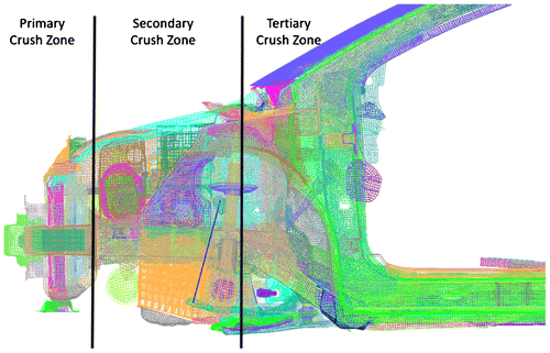
The open challenge in the current automotive domain is to offer the most qualitative safety and comfort to the occupants inside the car cabin area. In that aspect, many researches are being carried out to effectively control the parameters which effect the crashworthiness at a high speed crash analysis. In a typical crash analysis, the physical energy values are studied at various crush zones of the vehicle. Basically, the crush zones can be divided into three phases which can be named as the primary crush zone, secondary crush zone and tertiary crush zone as shown in the Figure . At the time of car frontal crash accidents, the energy gained at the primary zone will be dissipated to the tertiary zone through secondary zone. The supreme challenge for the automotive industry is to reduce the intensity of energy level in the tertiary zone. In the overall vehicle energy balance, the kinetic energy and Internal energy behavior in the crush zones are monitored for the certification of the vehicle’s ability for crashworthiness. Majority of the vehicle components undergo crushing deformation in these zones and transfer the kinetic energy and absorb internal energy. In that aspect, if most of the kinetic energy is converted into internal energy and if the internal energy for all the components in this zone increases, it is obvious that a minimum energy is transferred to the vehicle interior structure, which will reduce the risk of injury to the occupants. The energy absorption influencing parameters can be the materials, shapes of the structure, the connected parts and the physical design. Hussain, Regalla, and Rao Yendluri (Citation2017) analysed the crashworthiness properties of glass fibre reinforced plastic (GFRP) composite crash box columns with intrinsic buckling initiators for square, cylindrical, hexagonal and decagonal cross sections.
Abraham, Ghosh, Simms, Thomson, and Amato (Citation2016) researched on impact angle and collision velocity in run off road collisions and performed analysis on finite element model to evaluate the concrete barriers in non-standard collisions. Azimi and Asgari (Citation2016) investigated axial loading deformation properties of conical tubes called miniature frusta to study the non-symmetrical crush patterns, material and geometrical nonlinearity of conical frusta. The effect of thickness, semi-epical angle and specimen length on energy absorption characteristics are analysed by performing a parametric study. Dagdeviren, Yavuz, Kocabas, Unsal, and Esat (Citation2016) researched the impact of chassis geometry over crashworthiness constants of a ladder frame chassis for full frontal and pole side impacts. The hexagonal, square and rectangular cross sections were analysed through finite element modelling to understand the crushing mechanics of chassis component. Chiu and Jenq (Citation2014) studied the axial crushing of thin-wall metallic tubes with circular and modified circular hole triggering mechanisms. It was concluded that 11.7% decrease in the initial peak force for circular hole trigger and 14.6% diminish in initial peak force for a modified circular-hole triggering mechanism.
Kim, Shin, Lee, and Kwon (Citation2014) and Kim et al. (Citation2017) investigated an aluminium/carbon fibre reinforced polymer (Al/CFRP) hybrid square hollow beam with various combinations of laminate thickness and stacking sequence under transverse impact loading using three-point bending test. It was found that Al/CFRP hybrid square hollow section beam unveiled the better specific energy absorption, which was 28% greater than that of a traditional aluminium beam. Obradovic, Boria, and Belingardi (Citation2012) investigated that the carbon fiber reinforced plastic impact attenuator with a composite nose cone geometry for the quasi-static test and dynamic stroke applications. A progressive reduction of the wall thickness is considered as trigger for better energy absorbing characteristic. Mahmoudabadi and Sadighi (Citation2011) studied honeycomb geometry crushing under quasi-static loading for properties like the average crushing stress, kinetic energy absorption and the wavelength of the folding shape for impact loading. Toksoy and Guden (Citation2010) investigated aluminium closed-cell foam filled aluminium crash boxes for quasi-static and dynamic velocities. It was found that the partial foam filling inclined to change the deformation mode of non-filled boxes from a non-sequential to a sequential deformation mode. It was concluded that both fully and partially foam filled crash boxes were more efficient than empty boxes.
Meran (Citation2016) analysed the consequences of solidity and cross-sectional dimension on crashworthiness constants of thin walled columns under dynamic axial impact loading condition. The cross-sectional shapes studied in the research are hexagonal, triangular, octagonal, square, circular and multi cell shapes. The research result shows that the crushing strain of triangular tubes was better than square multi-cell tube. It is also found that the solidity parameter is inversely proportional to that of the crushing strain. Xie, Yang, Li, and Wang (Citation2017) investigated the single- and multi-cell, square tubes for crashworthiness under axial loads. The polynomial response surface method (PRSM) technique was used in this research for response surface models. The various dimensional criterions considered in the study are the number of cells, side-length and wall thickness in the structure. It was concluded that the thin-walled square column, with the same number of cells and the specific energy absorption, rises with thickness and falls with side-length. The initial peak force magnifies with side-length and wall thickness, whereas mean crush force intensifies with thickness but remains constant with side-length. Priem, Othman, Rozycki, and Guillon (Citation2014) examined 2.5D braided thermoplastic composite tubes for three crushing modes like splaying and progressive folding for glass/polypropylene tubes and fragmentation mode was analysed for carbon/polyamide tubes. It was found that the fragmentation mode has the highest specific energy absorption. The progressive folding mode has comparatively higher specific energy absorption than the splaying mode. It was also concluded that, the specific energy absorption increases with increasing braiding angle and decreasing length-to-diameter ratio for glass/polypropylene tubes. On the opposite, the specific energy absorption decreases with braiding angle for carbon/polyamide tubes. Tanlak and Sonmez (Citation2014) worked on shape optimization to upgrade the crashworthiness of thin-walled tubes under axial impact loads. As a part of it, the design variables and parameters defining the cross-sectional profile of the tube as well as parameters defining the longitudinal profile like the depths and lengths of the circumferential ribs and theta per angle were considered. The outcome was observed as a significant improvement in the crashworthiness over the benchmarks designs like circular and rectangular shapes. Qureshi and Bertocchi (Citation2012a) suggested a new design for automotive crash box-beam with sinusoidal patterns embedded on the beam surfaces and found that crash energy absorption is very promising by changing the wavelength of progressive buckle formations and because of that the denser collapse formations can be showcased. Besides, it was found that the relief patterns are the effective means to change the buckling modes and shorten the buckle wave length. Qureshi and Bertocchi (Citation2012b) evaluated the feasibility of using conventional notch triggers on sinusoidal patterns beams and observed that progressive triggering through variable pattern formulation potently triggers and commence more stable collapse. It is highly predominant that, progressive triggers cause less stray distortions along the beam and are resulting much more robust against global bending. Wu, Li, Sun, Wu, and Li (Citation2014) accomplished that thin-walled structures are habitual in showcasing unstable collapse modes and high initial peak crushing force (IPCF), followed by noisy force-displacement curves under impact loading. So, they investigated sinusoidal corrugation tube (SCT), to control the collapse mode as well as to reduce the IPCF and distortions by governing the parameters like the wavelength, amplitude, thickness and diameter of SCT and unearthed that the IPCF and disorders in the force–displacement curves are reduced substantially in SCT compared with the traditional straight circular tube.
All the research works cited above talk about the various materials and physical geometries like multi cell columns, filament wounded composite tubes with thermoset polymer matrix, 2.5D braided thermoplastic composite tubes, circular tubes, rectangular tubes, hexagonal tubes, crash box-beam with sinusoidal patterns embedded on the beam surfaces, conventional notch triggers on sinusoidal patterns beams and sinusoidal corrugation tube for superior energy absorption criteria. Among the different forms of structures and materials, the notch triggers on sinusoidal pattern beams and sinusoidal corrugation tubes unveil the challenging dominance over the other shapes and structures. Nevertheless, more researches are being performed on sinusoidal pattern shapes and notch triggers. In this mania, limited number of research work is accessible for the study of crashworthiness constants by removing the material, which gives an advantage of reducing the mass and weight of the component. However, the above mentioned studies do not give complete details on the crashworthiness performance of introducing a sequential V-notch and Horizontal groove triggers on the structure compared to the nominal geometry.
Consequently, achievements are made to interpret the crashworthiness variables for empty hollow tube (EHT), empty hollow tube with V-notch (EHTV) and empty hollow tube with horizontal groove (EHTHG) made of Aluminium 6063 material under an axial quasi-static loading conditions. Quite a several trails were performed on EHT, EHTV and EHTHG samples with various feed rate. The experimental test results were correlated with numerical results to discourse the crashworthiness constants and the modes of deformations. Also, a detailed study has been carried out to investigate the effect of notch and groove triggers on the crashworthiness parameters. All the above discussed corresponding sequels are presented in this article.
2. Background theory
2.1. Basic folding mechanism
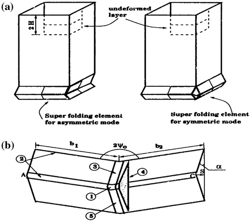
In the design of energy dispensing structures, the hypothesis of thin-walled columns has been recognized as very effective energy absorbing methodology. In this type of system, energy absorption will occur in a conjunction of progressive folding and bending collapse. Progressive crushing of a prismatic column involves subsequent deformation of a consecutive layer. Two potential buckling modes of a single layer are shown in Figure (a). The common buckling mode of a single super folding element is shown graphically in Figure (b) (Santosa & Wierzbicki, Citation1998).
2.2. Principle of virtual velocity
The principle of virtual velocities is used to demonstrate equilibrium of superfolding element. For axial crushing circumstance of one-dimensional problem, the virtual velocity principle equation can be conveyed in the form of:(1)
(1)
where δ is a prescribed velocity of an axial compression process, P is the reacted axial force, while σ and ε are the statically and kinematically admissible fields. The product Pδ represents the rate of work of external forces.
The total plastic work is proportional to the mean crushing force Pm, defined by the integrating Equation (1) with respect to the process parameter from α = 0 to α = αf(2)
(2)
2.3. Governing equation of single superfolding element
The energy balance in Equation (2) can be obtained by summation of all the endowment of plastic mechanism. Each contributing term has different functional dependence on unknown parameters r and H, so that the governing Equation (2) can be expressed as:(3)
(3)
where the coefficients Ai depend on switching parameter α and ψ0. A2 and A4 can be calculated as closed-form functions of geometrical parameters, while A1 and A3 are the functions of elliptic integrals and they must be calculated numerically. The effective crushing distance δef can be calculated from the terminal shape of completely squeezed corner elements by assuming that the actual pattern of deformed corner line is composed of alternating circular arcs. It can be shown through simple calculations performed for a right angle element that δef/2H = 0.73 (Abramowicz, Citation1983).
The mean crushing load Pm is thus a function of two unknown parameters H and r, which are determined from the condition (2) as:(4)
(4)
2.4. Crushing strength of a square box Colum
Consider a square column with the cross section b × b and the thickness of t. It is assumed that the box column undergoes a quasi-inextensional mode. In the current case, the constants A1, A2, A3 in Equation (Equation3(3)
(3) ) can be calculated by setting ᾱ = αf = π/2, and ψ0 = π/4. Using the above values, the coefficients A1 through A3 equal to A1 = 4.44, A2 = π, and A3 = 2.30. The energy balance Equation in (3) can then be rewritten in the form:
(5)
(5)
Note the coefficients A4 and A6 in Equation (Equation3(3)
(3) ) are vanishing because the lower and upper limits of integration in integral I4 and I6 are the same. Solution to the Equation (Equation5
(5)
(5) ) can be obtained by applying the minimum condition to the Equation (Equation4
(4)
(4) ). Hence physically meaningful values of r and H are obtained by minimizing Pm with respect to these parameters.
(6)
(6)
This leads to two simultaneous algebraic equations for r and H. The solution of this system is(7)
(7)
Since the section of square column is composed of four basic folding elements, all energies calculated in Equation (Equation5(5)
(5) ) should be multiplied by four. Consequently, the solution in Equation (7) should be multiplied by four for a square box column. Using the value of effective crushing distance δef = 0.73(2H), the crushing strength of square box column is then
(8)
(8)
For perfectly rigid plastic material with constant flow stress σ0, in which the plastic bending moment is M0 = σt2/4, the crushing strength of a square box column can be written as(9)
(9)
3. Specimen preparation and material properties
An extruded aluminium alloy with a material name as Al6063 was used to fabricate the specimen. Al6063 is light weight, commercially available and mostly used in automotive structures because of its excellent compressive properties (CitationReports on development of electric vehicle, 2000). As Al6063 is a highly strain rate independent (Kim, Citation2002), this effect can be ignored for the finite element modelling while the numerical simulation gets correlated. The chemical composition of Al6063 alloy has been studied as per OES-ASTM E-1251-11 standard and the outcome of chemical analysis is shown in the Table .
Table 1. Chemical composition of Al6063 aluminium alloy
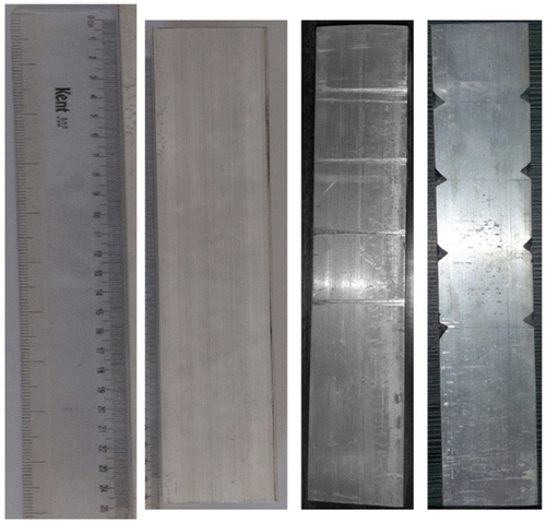
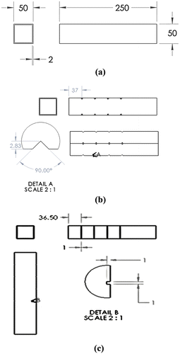
Three types of specimens have been fabricated using Al6063 alloy for the present research study. They are empty hollow tube (EHT), empty hollow tube with V-notch (EHTV) and empty hollow tube with horizontal groove (EHTHG). All the test specimens prepared for quasi static tests have been shown in the Figure respectively.
The 2D diagram of the test specimens was represented in the Figure (a–c) respectively. As discussed by Gomez and Elices (Citation2003), the crack initiation and propagation will be stable and more control on displacement can achieved for the notch angle of 90°. Also, it was discussed that the relative depth should be minimal for maximum load absorption. Xu et al. (Citation2016) showcased that the energy absorption and initial peak crushing force has a predominant influence on the groove depth value. In the current study, considering the thickness of the specimen the maximum possible groove depth of 1 mm was accounted. The basic peripheral dimension of the specimen is 50 × 50 × 250 mm (width × height × length) with a thickness of 2 mm. The typical automotive crash box width to thickness (W/T) ratio is about 27 to 30 mm (Kim et al., Citation2014), and the current value is closer to that of the crash box.
Figure 4. (a) Empty hollow tube (EHT), (b) Empty hollow tube V-notch (EHTV) and (c) Empty hollow tube horizontal groove (EHTHG).
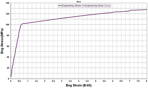
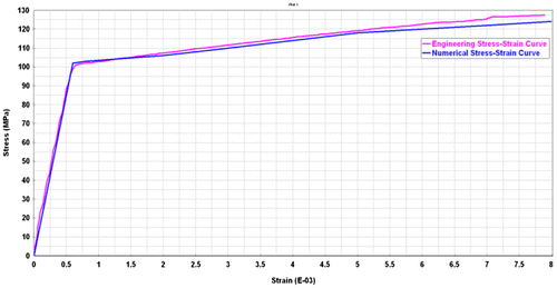
The uni-axial tensile properties of Al6063 alloy was studied as per ASTM B557 M – 15 standards using MTS Insight 100 KN Universal Testing machine. The physical material properties of the alloy were determined and shown in the Table . The dimensions of the test specimen like width, thickness and area are detailed in the Table . Also, that the gauge length values like initial gauge length, final gauge length and the load at the offset yield were presented. The peak load and the tensile strength of the alloy were determined to study the physical properties. The engineering stress-strain curve has been constructed using the parameters like Load, extension, time and extensometer readings. 0.2% proof stress is considered to determine the yield strength of the specimen. The computed engineering stress-strain curve of Al6063 is shown in the Figure .
Table 2. Physical material properties of Al6063 alloy
4. Resolution of crashworthiness constants
The quite essential constants like energy absorption (EA), mean crush force (Pm), specific energy absorption (SEA), peak force (Pmax), and crush force efficiency (CFE) are derived from the standard load-displacement curves of all the experimental and numerical results to determine the crashworthiness and its correlation.
Energy absorption (EA) is the major element which gauges the strength of crashworthiness. The area under the force–displacement curve gives the total energy absorption. Alternatively, the maximum internal energy of the component can also be considered as energy absorption. Analytically this constant can be calculated using the relation (10).(10)
(10)
where d is crush length and δ is displacement respectively and F is the crushing load. The mean crush force (Pm) was defined the ratio between the energy absorption (EA) and the maximum displacement δ. This parameter can be evaluated by the Equation (11).(11)
(11)
The mean crush force (Pm) determines the total capacity of energy absorption of a structure. The balanced total energy absorption by mass is required to examine the geometry or material discrepancy in the test specimens and it is pursued by specific energy absorption SEA. The greater the SEA value indicates that the crash box can become lighter. The specific energy absorption (SEA) is formulated by using an Equation (12).(12)
(12)
where m is the mass of the specimen. Higher SEA leads to a better energy absorption capacity of crash box with respect to the mass.
The crush force efficiency (CFE) or Force Uniformity Index (FUI) of a structure is the key indicator to showcase the crashworthiness capability of structural components. The parameter CFE is defined as the ratio between mean crushing force and maximum peak force (Kathiresan & Manisekar, Citation2016) and it can be calculated using the relation (13).(13)
(13)
where Pm and Pmax are the mean crushing force and peak force respectively.
The CFE reflects the unwavering behaviour of the applied force along the axial direction while crushing. So, higher the CFE embellish as a more ideal energy absorption phenomenon. Also, the high value of CFE indicates that the conduct of the specimen is close to the better energy absorber and the less noise in load–displacement curve and thus we can assure reduced injury to the occupants (Mirzaei, Shakeri, Sadighi, & Akbarshahi, Citation2012). If the percentage of CFE is close to hundred, it indicates that component deforms with maximum load without major catastrophic damages (Tarlochan & Ramesh, Citation2012) to the occupants in the cabin area. On the other side, if this percentage is away from hundred, there can be a random change in the mode of deformation during the crash analysis and therefore structural components may undergo a catastrophic failure which is not desired and should be strictly avoided in case of design of any crush energy-absorbing component (Guoxing & Tongxi, Citation2003). The more deviation in the value of CFE from hundred may induce a phenomenon of buckling during crash analysis which is the most undesirable mode while analyzing the for crashworthiness.
5. Experimentation and results
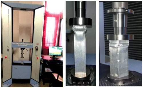
The quasi-static compression test is performed on Universal testing machine AG-X plus 50 KN capacity machine shown in the Figure . This testing machine has two compression plates/heads. The upper head is moveable, while the lower head is stationary. A load gauge is fitted for recording the applied load. Ends of the specimen should be plane and perpendicular to the moving head, for that the ends are tested on a bearing plate. The specimen is placed between the two compression heads, and of that the centre of moving head is vertically above the centre of specimen. Load is applied on the specimen by moving the movable head at a constant feed rate of 5 mm/min and 3.06 mm/s for crush length of 175 mm. The stress-strain curve and load-displacement curve are procured for the feed rates as an output from the experimental setup. With the above loading conditions, the specimens of type, empty hollow tube (EHT), empty hollow tube with V-notch (EHTV) and empty hollow tube with horizontal groove (EHTHG) were analysed for quasi-static loading with a feed rate of 5 mm/min and 3.06 mm/s. The load-displacement and deformation modes of the specimens for 5 mm/min are shown in Figure (a) and (b) and for 3.06 mm/min are shown in Figure (a) and (b).
Figure 7. (a) Force–displacement curve and (b) Deformation modes of EHT, EHTV and EHTHG specimens with 5 mm/min.

Figure 8. (a) Force–displacement curve and (b) Deformation modes of EHT, EHTV and EHTHG specimens with 3.06 mm/s.

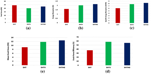
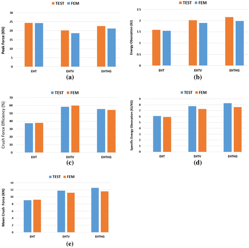
In static tests, empty hollow tube (EHT), empty hollow tube with V-notch (EHTV) and empty hollow tube with horizontal groove (EHTHG) square columns were subjected to an axial uniform quasi-static loading and their reaction against the crush force was logged as Force–displacement (F–S) curve. The (F–S) here represents to the reaction contact force between the UTM moving cross heads and the deformation of aluminum specimen. Some of the experimental F–S plots of various feed rates are documented. From the output curves, it was perceived that the test specimens were axially compressed with impact energy of 0.01 mJ for the 5 mm/min feed rate and 0.4 mJ for 3.06 mm/s feed rate, with a maximum displacement stroke of 175 mm accordingly. The buckling modes were found to be triggered in a very sequential manner for EHT, EHTV and EHTG specimens in case of low speed 5 mm/min and the progressive transmission of force is observed with a feed rate of 5 mm/min, whereas the buckling modes are not much sequential and progressive with a feed rate of 3.06 mm/s. This could be the reasons for noisy and highly disturbed F–S curves for higher feed rate of 3.06 mm/s. It was also observed that the buckling initiation is not in a sequence and progressive in case of higher feed rate, some of the crashworthiness parameters like crush length (d), total displacement (δ), crushing load (F) and peak force (Pmax) are obtained from the experimental output curves. The other parameters like EA, Pm, SEA and CFE are derived from the force–displacement (F–S) curves of EHT, EHTV and EHTHG specimens for 5 mm/min and 3.06 mm/s as per the stated Equations (10–13). The experimental results and crashworthiness parameters for 5 mm/min are showed in the Table and for 3.06 mm/s are showed in Table respectively. For the crushing speed of 5 mm/min, the crashworthiness constants Pmax and EA is quite promising for EHT, compared to EHTV and EHTHG. The same pattern of results was observed for Pm, SEA and CFE parameters too for 5 mm/min. In contradiction to the feed rate of 5 mm/min, the analysis results for 3.06 mm/s was found to be better for EHTV and EHTHG compared to EHT. The parameters Pmax and EA are higher for EHTV and EHTHG compared to EHT. Besides the Pm, SEA and CFE are found to be in better agreement for EHTV and EHTHG compared to EHT for the feed rate of 3.06 mm/s. The crashworthiness parameters like EA, Pm, SEA, Pmax and CFE for EHT, EHTV and EHTHG with a speed of 3.06 mm/s are shown in the Figure .
Table 3. Experimental results of EHT, EHTV and EHTHG for 5 mm/m
Table 4. Experimental results of EHT, EHTV and EHTHG for 3.06 mm/s
6. Numerical modelling and Simulation
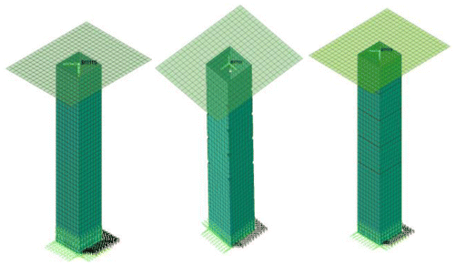
The numerical modelling simulations were carried out in a same fashion of experimental results only for the feed rate of 3.06 mm/s. Since the finite element simulation time for 5 mm/min was too high, it was ignored for numerical validation and correlation. For the finite element analysis, the numerical model element type is considered as thin shell element and meshed with an average element size of 6 mm, which is built using the ESI-GROUP’s preprocessor program Visual-Mesh and Visual Crash-PAM, which is mostly used commercial software for model setup in many of automotive industries. An explicit finite element analysis was performed with simulation time of 57.18 s. The numerical calculation was performed using the dynamic non-linear explicit code Virtual Performance Solution of PAM-CRASH module, owned by ESI-GROUP. The FEA model built in preprocessor is shown in the Figure .
The structure is modeled using 4-node Belytschko–Tsay and uniformly reduced shell integration rule. Material Type 103 provided by PAM-CRASH module was used for the shell element and it corresponds to elastic–plastic iterative hill criterion thin shell material models. Material type 103 uses an enhanced plasticity algorithm which includes transverse shear effects. It exactly satisfies Hill’s criterion and precisely updates the element thickness during plastic deformation (CitationVirtual Performance Solution, 2016). The yield stress formulation is used instead of isotropic hardening law and material constants like young’s modulus, yield stress and tangent modulus were derived from stress-strain curve obtained from the tensile test laboratory. The comparison of engineering stress-strain curve with numerical modeling stress-strain curve is shown in Figure .
Figure 11. Comparison of engineering stress-strain curve from tensile test with numerical modelling curve.
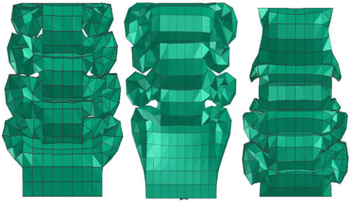
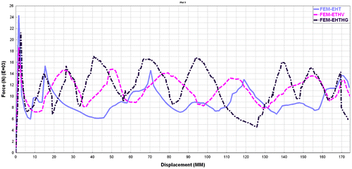
A rigid shell plate is modelled with rigid body for the moving cross heads and assigned with a null material. A qausi-static loading curve has been defined and assigned in a prescribed three-dimensional velocity option as a loading condition. The bottom most nodes in the numerical model are fixed in all the degrees of freedom to arrest the motion, as the bottom head in the UTM machine is not movable. The internal self-contact between the elements and the buckling zone is anticipated, so the well stable self-contact algorithm type 36 is applied for the specimen and non-symmetric node to segment with edge treatment contact algorithm type 34 is applied between rigid plate and deforming component. The displacement of center of gravity of rigid plate is requested for nodal displacement as an output by the solver. The cross plot of reaction force of contact type 34 and displacement magnitude of rigid plate COG node offers the F–S curve for the current quasi-static analysis. The post-processor Visual Viewer is used for visualization and curve plotting. The numerical deformation modes of EHT, EHTV and EHTHG is shown in Figure . The force–displacement (F–S) plots procured from numerical simulation of 3.06 mm/s speed were shown in the Figure . The crashworthiness constants are calculated and tabulated in the Table . The buckling initiation found to be in sync with that of the test and the deformation progression is uniform in case of numerical simulation also.
Table 5. Crashworthiness constants derived from FEM results for EHT, EHTV and EHTHG at 3.06 mm/s
The triggers or initiators were commonly used in the energy absorbing structures undergoing axial compressive crash. These initiators play a key role in controlling the deformation modes and smooth energy transfer during axial crash analysis. In the current research, the V-notch and horizontal grooves are considered as triggers, which are expected to lower the peak crushing load and to actuate progressive folding and refrain from global bending mode. The triggers are the prime initiators for the first elastic buckling mode. In this article, V-notch and Horizontal groove triggering mechanism is studied and analysed corresponding to the component without any triggers. The effect of triggers was perfectly evidenced in experimentation. It was found that the effect of triggers gives positive improvement in terms of crashworthiness parameters and also the buckling mode initiations of the structural component during quasi-static analysis.
7. Experimental and numerical correlation
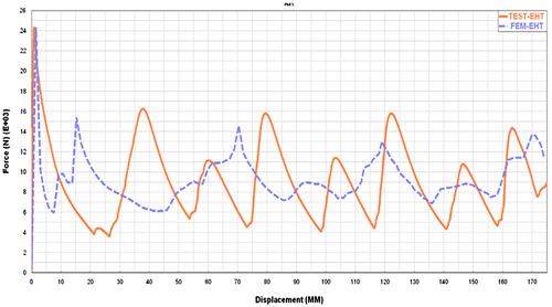
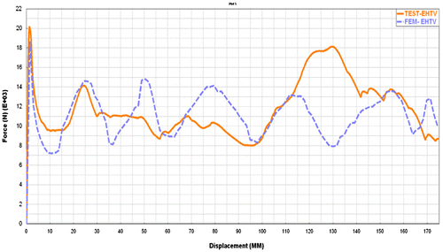
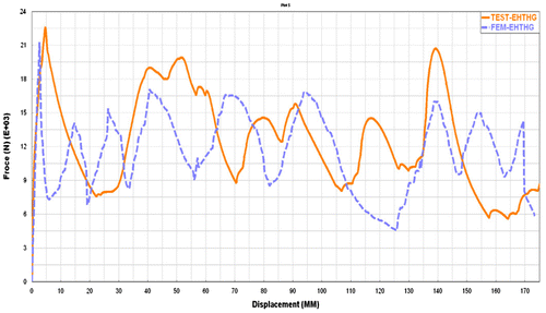
The force–displacement (F–S) plots procured from numerical simulation are compared with experimental curve output. Figures shows the comparison of test and simulation curves for EHT, EHTV and EHTHG specimens at 3.06 mm/s crushing rate. From the comparison plots, it was concluded that the deformation mode of F–S curves of experimental and FEA are in good synchronization. Table shows the more details of FEA and experimental test results. It was also observed that the percentage of relative error for energy absorption (EA) between FEA and experimental results varies from a range of 2.5–7.9% and 1.5–2.0% for CFE. This minimum error values substantiate the correlation of the FEA and experimental test procedures and the reliability of test results.
Table 6. Comparison of test and FEM results for EHT, EHTV and EHTHG specimen with 3.06 mm/s feed rate
The deformation modes of EHT, EHTV and EHTHG type specimen at specific instances of FEA are compared with the actual collapse pattern of the same sample through experimentation. From the comparison, the modes of collapse of EHT, EHTV and EHTHG specimens through FEA are in decent concurrence with the experimental collapse trend. The buckling initiations, crumpling of structure and the evolution of rolling plastic and wall hinges are clearly predicted through FEA to compare with the experimental results. Since the energy absorption is recorded as highest for EHTHG, the same trend has been reflected in SEA also. This can be evidenced in Figure (c).
The tendency of peak force (Pmax) and crush force efficiency (CFE) for EHT, EHTV and EHTHG samples was observed to be bit different for FEM when compared to test results. Whereas the biasing looks alike for other parameters like EA, Pm and SEA for EHT, EHTV and EHTHG samples. The bar charts are plotted to compare the results as shown in the Figure . The value of peak force (Pmax) in FEM showed as 7.5% more than experiment results. This could be because of some imperfections while fabricating the specimen with V-notch and grooves. Some abrupt peaks were recorded in FEM results compare to experimental results for EHTV and EHTHG specimens. This could be because of the numerical assumptions in definition of self-contact. Also the friction value and contact thickness used in numerical simulation may have some adverse effects.
8. Results discussion and conclusion
8.1. Exploration of force–displacement (F–S) mode
In experimental test, the extruded Al6063 specimens of type empty hollow tube (EHT), empty hollow tube with V-notch (EHTV) and empty hollow tube with horizontal groove (EHTHG) were subjected to an axial quasi-static loading and their toughness against crush force was plotted as force–displacement (F–S) curve.
The experimental results convey that the EHT type structures are recorded with higher level of Peak load (Pmax) compared to EHTV and EHTHG samples. It was observed that the V-notch and groove triggers plays an important role to acquire the Pmax and Pm levels. The other crashworthiness parameters such as EA, SEA and CFE are derived from Pmax and Pm values of each specimen and the results are shown in Table . From the Figure (a), it confirms that the peak load (Pmax) is the highest for EHT and higher for EHTHG when it is compared to EHTV. It becomes possible because the horizontal groove is extended laterally over the specimen area. The Figure (b) describes that the EA is not related with factor Pmax, as the EA is the highest for the EHTHG while it is compared to EHT and EHTV. The horizontal groove triggers initiate a progressive buckling mode and unique deformation which results in better energy absorption characteristic for EHTHG as the horizontal groove increases the energy absorption capability by 56% to that of EHT and EHTV.
The crush force efficiency (CFE) of EHT is recorded as lowest compared to EHTV and EHTHG specimens. But the CFE of EHTHG is marginally less than that of EHTV. This is because of the ratio between Pm and Pmax. It is bit inferior to that of EHTV. This behaviour was showcased in Figure (e) from the plots of CLE, the percentage value of CLE for EHTV and EHTG is closer to the value of hundred, it means that, the hallow structures with V-notch or groove are prone to be more efficient compared to structures without any buckling triggers or initiators. Also, it showcases that EHTV and EHTHG specimens are more proficient in absorbing the crushing load progressively.
8.2. Discussion on feed rate
The experimental results for empty hollow tube (EHT), empty hollow tube with V-notch (EHTV) and empty hollow tube with horizontal groove (EHTHG) with feed rate of 5 mm/min was shown in the Table . This data demonstrates that crashworthiness parameters behaviour significantly changes with the effect of feed rate. The reason for this phenomenon could be that, as the feed rate is predominantly very less, there is a significant impact of reaction forces for quasi -static loading conditions. All the crashworthiness constants like EA, SEA and CFE decline because of the introduction of V-notch and Horizontal grooves. This result showcases that EHTV and EHTHG specimens are not much recommendable for energy absorption desired situations.
8.3. Discussion on buckling initiators
Notch or groove triggers do not remarkably diminish the total amount of energy absorption though it minimizes the initial force spikes. It can be concluded that triggers or buckling initiators play a key role in controlling the crashworthiness parameters like EA, SEA and CFE at quasi-static loading conditions. Some of the observations evidenced that because of the usage of triggers or buckling initiators, the preliminary spike force during the introductory stage of the collapse should be reduced. The buckling has to initiate at an expected location and it must be inaugurated into a succeeding, methodical, systematic and periodic collapse mode.
It was also noticed that the effect of buckling initiators was highly dependent on the crushing feed rate and its experimental process parameters. As per the experimental results shown in Tables and , the initiators are not advisory for very low speed impacts. As the feed rate is very less in case of low speed impacts, the effect of the triggers is very much negligible at low velocity impacts. This attitude is predominantly useful in the interpretation of high speed impact energy absorbers during oblique loading, where globalized bending or kneeing-out is a familiar unenviable failure mode.
Funding
The authors received no direct funding for this research.
Additional information
Notes on contributors
G. Balaji
G. Balaji is a research scholar and pursuing his research in the Department of School of Mechanical and Building Sciences, VIT University, Chennai, India. He has a rich experience in product business development, quality assurance and technical support of automotive Computer Aided Engineering software. His research interest includes automotive vehicle crashworthiness refinement, intensifying crash energy absorption and enrichment of overall full car vehicle crash and safety performance for crash analysis.
References
- Abraham, N., Ghosh, B., Simms, C., Thomson, R., & Amato, G. (2016). Assessment of the impact speed and angle conditions for the EN1317 barrier tests. International Journal of Crashworthiness, 21, 211–221.10.1080/13588265.2016.1164444
- Abramowicz, W. (1983). The effective crushing distance in axially compressed thin-walled metal columns. International Journal of Impact Engineering, 1, 309–317.10.1016/0734-743X(83)90025-8
- Azimi, M. B., & Asgari, M. (2016). Energy absorption characteristics and a metamodel of miniature frusta under axial impact. International Journal of Crashworthiness, 21, 222–230.10.1080/13588265.2016.1164445
- Chiu, Y.-S., & Jenq, S.-T. (2014). Crushing behavior of metallic thin-wall tubes with triggering mechanisms due to quasi-static axial compression. Journal of the Chinese Institute of Engineers, 37, 469–478.10.1080/02533839.2013.800275
- Dagdeviren, S., Yavuz, M., Kocabas, M. O., Unsal, E., & Esat, V. (2016). Structural crashworthiness analysis of a ladder frame chassis subjected to full frontal and pole side impacts. International Journal of Crashworthiness, 21, 477–493.10.1080/13588265.2015.1135522
- Gomez, F. J., & Elices, M. (2003). Fracture of components with V-shaped notches. Engineering Fracture Mechanics, 70, 1913–1927.10.1016/S0013-7944(03)00131-0
- Guoxing, L., & Tongxi, Y. (2003). Energy absorption of structures and materials (pp. 1–23). Woodhead Publishing Limited. doi:10.1533/9781855738584.frontmatter
- Hussain, N. N., Regalla, S. P., & Rao Yendluri, V. D. (2017). Numerical investigation into the effect of various trigger configurations on crashworthiness of GFRP crash boxes made of different types of cross sections. International Journal of Crashworthiness, 22, 565–581. doi:10.1080/13588265.2017.1286964
- Kathiresan, M., & Manisekar, K. (2016). Axial crush behaviours and energy absorption characteristics of aluminium and E-glass/epoxy over-wrapped aluminium conical frusta under low velocity impact loading. Composite Structures, 136, 86–100.10.1016/j.compstruct.2015.09.052
- Kim, H. C., Shin, D. K., Lee, J. J., & Kwon, J. B. (2014). Crashworthiness of aluminum/CFRP square hollow section beam under axial impact loading for crash box application. Composite Structures, 112, 1–10.
- Kim, H.-S. (2002). New extruded multi-cell aluminum profile for maximum crash energy absorption and weight efficiency. Thin-Walled Structures, 40, 311–327.10.1016/S0263-8231(01)00069-6
- Kim, S.-Y., Jeong, J.-W., Kim, J.-Y., Kim, H.-C., Shin, D.-K., Shin, K.-C., & Lee, J.-J. (2017). Energy absorption characteristics of aluminium/CFRP hybrid beam under impact loading. International Journal of Crashworthiness, 22, 190–201.10.1080/13588265.2016.1243637
- Mahmoudabadi, M. Z., & Sadighi, M. (2011). A theoretical and experimental study on metal hexagonal honeycomb crushing under quasi-static and low velocity impact loading. Materials Science and Engineering, 528, 4958–4966.10.1016/j.msea.2011.03.009
- Meran, A. P. (2016). Solidity effect on crashworthiness characteristics of thin-walled tubes having various cross-sectional shapes. International Journal of Crashworthiness, 21, 135–147.10.1080/13588265.2015.1127584
- Mirzaei, M., Shakeri, M., Sadighi, M., & Akbarshahi, H. (2012). Experimental and analytical assessment of axial crushing of circular hybrid tubes under quasi-static load. Compos Structures, 94, 59–66.
- Obradovic, J., Boria, S., & Belingardi, G. (2012). Lightweight design and crash analysis of composite frontal impact energy absorbing structures. Composite Structures, 94, 423–430.10.1016/j.compstruct.2011.08.005
- Priem, C., Othman, R., Rozycki, P., & Guillon, D. (2014). Experimental investigation of the crash energy absorption of 2.5D-braided thermoplastic composite tubes. Composite Structures, 116, 814–826.10.1016/j.compstruct.2014.05.037
- Qureshi, O. M., & Bertocchi, E. (2012a). Crash behavior of thin-walled box beams with complex sinusoidal relief patterns. Thin-Walled Structures, 53, 217–223.10.1016/j.tws.2011.12.006
- Qureshi, O. M., & Bertocchi, E. (2012b). Crash performance of notch triggers and variable frequency progressive-triggers on patterned box beams during axial impacts. Thin-Walled Structures, 63, 98–105. https://doi.org/10.1016/j.tws.2012.07.021
- Reports on development of electric vehicle. (2000). Korea Advanced Institute of Science and Technology, Public university in Daejeon, South Korea. Retrieved from http://www.kaist.ac.kr
- Santosa, S., & Wierzbicki, T. (1998). Crash behavior of box columns filled with aluminum honeycomb or foam. Computers and Structures, 68, 343–367.10.1016/S0045-7949(98)00067-4
- Tanlak, N., & Sonmez, F. O. (2014). Optimal shape design of thin-walled tubes under high-velocity axial impact loads. Thin-Walled Structures, 84, 302–312.10.1016/j.tws.2014.07.003
- Tarlochan, F., & Ramesh, S. (2012). Composite sandwich structures with nested inserts for energy absorption application. Composite Structures, 94, 904–916.10.1016/j.compstruct.2011.10.010
- Toksoy, A. K., & Guden, M. (2010). Partial Al foam filling of commercial 1050H14 Al crash boxes: The effect of box column thickness and foam relative density on energy absorption. Thin-Walled Structures, 48, 482–494.10.1016/j.tws.2010.02.002
- Virtual Performance Solution. (2016). PAM-CRASH Explicit solver reference manual. Paris: ESI-GROUP Software Product Co. Retrieved from http://www.esi-group.com
- Wu, S., Li, G., Sun, G., Wu, X., & Li, Q. (2014). Crashworthiness analysis and optimization of sinusoidal corrugation tube. Thin-Walled Structures, 63, 98–105. doi:10.1016/j.tws.2012.07.021
- Xie, S., Yang, W., Li, H., & Wang, N. (2017). Impact characteristics and crashworthiness of multi-cell, square, thin-walled, structures under axial loads. International Journal of Crashworthiness, 1–15.
- Xu, P., Yang, C., Peng, Y., Yao, S., Xing, J., & Li, B. (2016). Cut-out grooves optimization to improve crashworthiness of a gradual energy-absorbing structure for subway vehicles. Materials and Design, 103, 132–143.10.1016/j.matdes.2016.04.059

