 ?Mathematical formulae have been encoded as MathML and are displayed in this HTML version using MathJax in order to improve their display. Uncheck the box to turn MathJax off. This feature requires Javascript. Click on a formula to zoom.
Abstract
This article presents a simple method of designing a fractional filter PID controller for second order plus time delay (SOPTD) processes using internal model control (IMC) scheme. There has been limited number of tuning rules for SOPTD processes developed using direct synthesis method and IMC method. The proposed IMC-PID controller using fractional IMC filter results in a controller structure composed of PID controller cascaded with fractional filter. Simulations have been performed on several second order lag dominant and delay significant processes. Robustness checks are performed for variations in the process parameters and robustness analysis is carried out using sensitivity functions. The proposed controller results in an enhanced control performance for nominal process parameters and with parameter variations. In addition, the effect of measurement noise is also studied for set point tracking and load disturbance variations.
Public Interest Statement
Each process needs a precise control in our day to day life to produce a desired and accurate output. On a broader scale, control has become a major and important part of all types of industries that produces different products. The ultimate aim of production is that the products should meet the predefined specifications to satisfy the needs of end user. Hence, a control system with proper control structure needs to be incorporated to control different aspects of the processes. This article proposes one such structure of the controller designed with internal model control using fractional filter. The design is validated on several industrial processes modeled as second order systems to produce desired output for different types of inputs acting on them. Further, the robustness of the design is verified for different plant conditions. These analyses help engineers in identifying the best control structure to produce desired output.
1. Introduction
Proportional Integral Derivative (PID) controller has been the main choice for industrial sector applications from centuries. In spite of the advancements in control, PID controller is still being used by 90% of the applications due to its ability to control wide range of industrial processes (Shamsuzzoha, Citation2013). Moreover, the simple structure and the availability of tuning rules contribute to the wider use of PID controller (Astrom & Hagglund, Citation1995; Skogestad, Citation2003). However, the controller tuning methods are still evolving to ensure improved closed loop performance of the processes as they are associated with time delays, external perturbations and non-linearities (Jeng, Tseng, & Chiu, Citation2014; Lee, Cho, & Edgar, Citation2013; Ranganayakulu, Uday Bhaskar Babu, & Seshagiri Rao, Citation2016; Silva, Datta, & Bhattacharyya, Citation2007; Vilanova & Visioli, Citation2012). The real processes need to be approximated as lower order models for the application of PID tuning rules. The SOPTD models represent better dynamics of the processes than first order plus time delay (FOPTD) models. The PID tuning rules for SOPTD processes are less (Panda, Yu, & Huang, Citation2004; Weigand & Kegerreis, Citation1972) in number compared to FOPTD processes. Hence, the current work is carried out on SOPTD processes.
The direct synthesis (DS) method and internal model control (IMC) schemes are mostly used for designing the controller for SOPTD processes (Chen & Seborg, Citation2002; Lee, Park, Lee, & Brosilow, Citation1998; Panda et al., Citation2004). DS controllers are designed for the desired trajectory of the closed loop transfer function. But, the design not necessarily results in a PID form of controller. Direct synthesis controllers are suitable for set point tracking and don’t give satisfactory performance for disturbance rejection. The IMC based design results in a PID controller structure by proper approximation of the process model. Several controller tuning methods based on IMC-PID method have been proposed for SOPTD processes. The design was based on the selection of optimum IMC filter and controller structure (Shamsuzzoha & Lee, Citation2007, Citation2008). An analytical method of designing IMC-PID controller was proposed for all kinds of time delay systems (Shamsuzzoha, Citation2015). For improved disturbance rejection a PID controller cascaded with lead-lag compensator has been used (Rao, Rao, & Chidambaram, Citation2009; Shamsuzzoha & Lee, Citation2008). Further, the overshoot in servo response was reduced by utilizing set point weighting. An optimal tuning method for SOPTD processes by optimizing integral of absolute error (IAE) was also proposed (Madhuranthakam, Elkamel, & Budman, Citation2008). A graphical method of obtaining PID controller parameters for SOPTD processes through dominant pole placement approach with assured gain margin and phase margin was also proposed (Srivastava & Pandit, Citation2016).
Some of the design methods presented above are suitable for set point tracking while others were exclusively designed for disturbance rejection. A few of the design procedures doesn’t guarantee the PID form of controller structure which is widely used in industries while still providing better closed loop performance. Though, the IMC based methods had only one tuning parameter they have used set point weighting and set point filter along with controller to suppress the overshoot. So, there was a need to choose the weighting factor or filter parameter along with the controller settings. Recently, an IMC-PID controller was proposed using pole zero conversion with an unified IMC filter structure (Wang, Lu, & Pan, Citation2016). The design also used derivative coefficient weighting along with pole zero conversion to obtain the controller settings for SOPTD processes. Also, the overshoot was minimized with set point weighting technique. Majority of the controllers designed for SOPTD processes were based on the use of higher order IMC filter (second to fourth order) and by using optimization. The current work focuses on the design of a simple IMC-PID controller using fractional IMC filter for SOPTD processes. The resulting controller structure consists of a PID in series with fractional filter. The performance metrics like integral of square error (ISE), integral of absolute error (IAE), percentage overshoot (%OS) and maximum sensitivity (Ms) are used to estimate the closed loop performance of SOPTD processes. The effectiveness of the present method is illustrated with simulations carried out on over damped and critically damped SOPTD processes using MATLAB and Simulink. In addition, the simulation is carried out on a higher order process reduced to SOPTD process. The effects on process output performance in presence of parametric uncertainties and output noise have also been discussed.
2. Fractional filter IMC-PID controller design
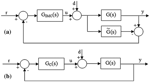
The IMC scheme and feedback control loop with internal blocks are shown in Figure , where G(s), GIMC(s) and GC(s) representing process, process model, IMC controller and transfer function of the traditional controller. Let r, y, u and d be the set point, controlled variable, control input and disturbance respectively. The controller design using IMC method is given as follows:
(1) Decompose the process model into non-invertible and invertible parts(1)
(1)
where is non-invertible contains all time delays and unstable zeros.
is invertible and contains minimum phase elements.
(2) The IMC controller is given by
(2)
(2)
where f(s) is the IMC filter
(3) The equivalent feedback controller is
(3)
(3)
2.1. Proposed IMC-PID controller design
The proposed controller has the structure(4)
(4)
Consider a SOPTD model(5)
(5)
where K–the system gain, L–time delay and T1, T2 are the process time constants.
The fractional IMC filter used is(6)
(6)
where γ is the fractional filter time constant and p is the fractional order. Now, the IMC controller according to Equation (2) is(7)
(7)
Finally, the fractional filter IMC-PID controller from (3), (5) and (7) is(8)
(8)
(9)
(9)
The delay e-Ls expressed as a first order fraction according to Pade’s rule is
(10)
(10)
Now, the controller becomes
(11)
(11)
The above equation can be written as
(12)
(12)
Comparing Equations (4) and (12), the controller settings are
(13)
(13)
and the fractional filter is
(14)
(14)
2.2. Robustness analysis
The closed loop stability of system should be verified in presence of model uncertainties for robustness of the designed controller which is derived under nominal process conditions. The designed controller should be able to provide better closed loop performance (good servo response and regulatory response) irrespective of the perturbations in process parameters which are common in practice. The controller that ensures good response characteristics for perturbations in system gain, time delay and time constant is said to be robust. This robust stability of closed loop system can be verified with small gain theorem (Maciejowski, Citation1989; Morari & Zafiriou, Citation1989). According to this theorem, the closed loop system will be robustly stable if and only if(15)
(15)
where T(s) and lm(s) are the complementary sensitivity function and the bound on multiplicative uncertainty. They are defined as
(16)
(16)
(17)
(17)
where G(s) is the real process representing the nominal model (Equation (5)); is the actual model of the process.
In addition to the condition for robust stability in Equation (15), the following inequality constraint must hold good to ensure robust closed loop performance.(18)
(18)
where S(s) is the sensitivity function which can be found from S(s) = 1 − T(s) and wm(s) is the multiplicative uncertainty bound on the sensitivity function.
3. Results and discussion
The performance of different SOPTD processes with the designed controller is analyzed and was compared with the control performance obtained from Wang et al. (Citation2016) tuning method. Several SOPTD processes representing lag dominant and balanced/delay significant process dynamics are considered for simulation. In addition, the simulations are performed on a higher order process reduced to SOPTD model. The performance metrics used for comparison are: integral of square error (ISE), integral of absolute error (IAE), percentage overshoot (%OS) and maximum sensitivity (Ms). The0se performance indices are defined as follows:
(19)
(19)
(20)
(20)
(21)
(21)
(22)
(22)
The simulation scheme is shown in Figure
. The closed loop response was observed for a step set point changes of unit magnitude with load disturbance. The quality of response was verified by introducing a white noise in the output. It is to be noted that the fractional term in fractional filter of the controller is approximated using Oustaloup method. The frequency range used for approximation is 0.01–100 rad/s with an approximation order of 5.Figure 3. Closed loop response for G1: Proposed method (red solid line), Wang et al. (Citation2016) method (blue dotted line).
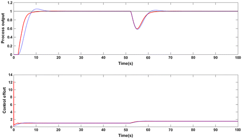
Table 1. Comparison of closed loop performance of the examples
Figure 4. Response for +10% uncertainty in gain and time delay for G1: Proposed method (red solid line), Wang et al. (Citation2016) method (blue dotted line).
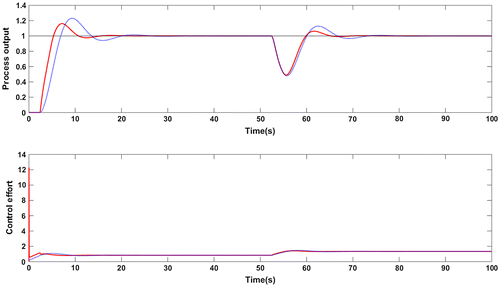
Figure 5. Closed loop response in presence of measurement noise for G1: Proposed method (red solid line), Wang et al. (Citation2016) method (blue dotted line).
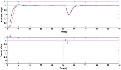
Table 2. Performance comparison with measurement noise
Figure 6. Magnitude plot for G1: Complementary sensitivity function (red solid line),+10% uncertainty in time delay (green dotted line).
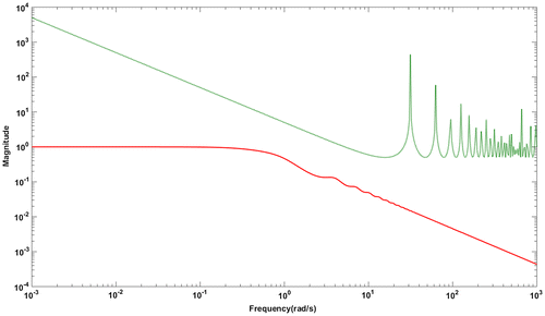
Figure 7. Closed loop response for G2: Proposed method (red solid line), Wang et al. (Citation2016) method (blue dotted line).
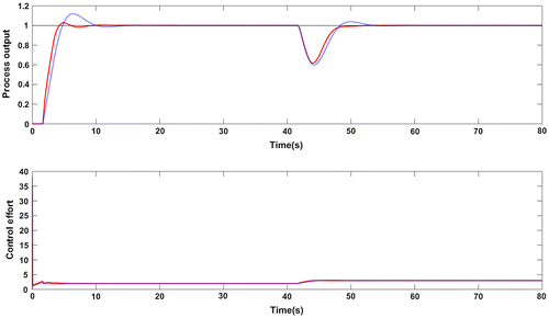
Table 3. Performance comparison for G2 with proposed method at different values of fractional order (p)
Figure 8. Response for +10% uncertainty in gain and time delay for G2: Proposed method (red solid line), Wang et al. (Citation2016) method (blue dotted line).
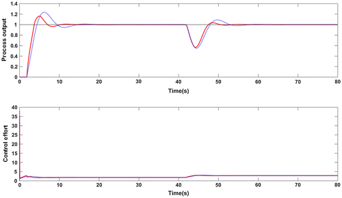
Figure 9. Closed loop response in presence of measurement noise for G2: Proposed method (red solid line), Wang et al. (Citation2016) method (blue dotted line).
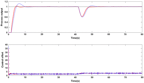
Table 4. Performance comparison for G4 with proposed method at different values of fractional order (p)
Figure 11. Magnitude plot for G2: Complementary sensitivity function (red solid line),+10% uncertainty in time delay (green dotted line).
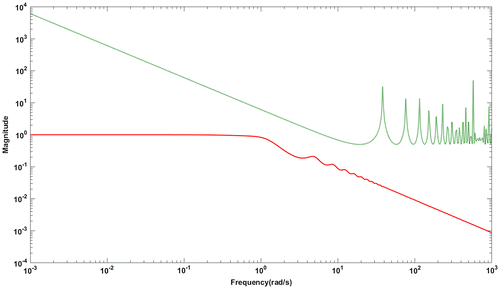
Figure 12. Closed loop response for G3: Proposed method (red solid line), Wang et al. (Citation2016) method (blue dotted line).
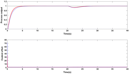
Figure 13. Response for +10% uncertainty in gain and time delay for G3: Proposed method (red solid line), Wang et al. (Citation2016) method (blue dotted line).
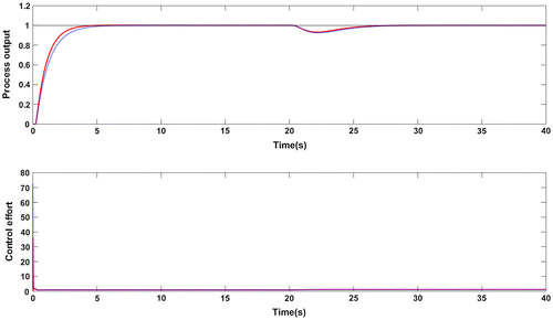
Figure 14. Closed loop response in presence of measurement noise for G3: Proposed method (red solid line), Wang et al. (Citation2016) method (blue dotted line).
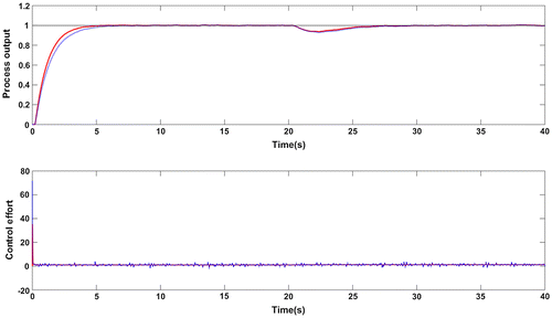
Figure 15. Magnitude plot for G3: Complementary sensitivity function (red solid line),+10% uncertainty in time delay (green dotted line).
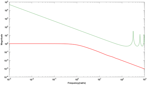
Figure 16. Closed loop response for G4: Proposed method (red solid line), Wang et al. (Citation2016) method (blue dotted line).
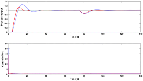
Figure 17. Response for +10% uncertainty in gain and time delay for G4: Proposed method (red solid line), Wang et al. (Citation2016) method (blue dotted line).
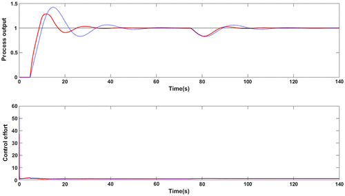
Figure 18. Closed loop response in presence of measurement noise for G4: Proposed method (red solid line), Wang et al. (Citation2016) method (blue dotted line).
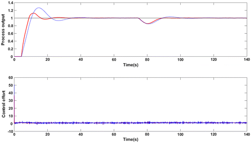
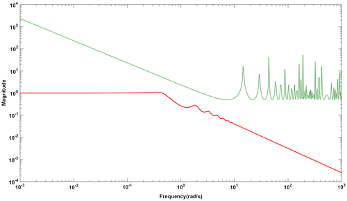
Figure 20. Magnitude plot for G4: Complementary sensitivity function (red solid line), +10% uncertainty in time delay (green dotted line).
Example 1
Consider the delay significant SOPTD process as studied in (Lee et al., Citation2013)(23)
(23)
The controller obtained for the above process with proposed method is given in Equation (24). The filter time constant was chosen as γ = 2 and the fractional order p = 1.02.(24)
(24)
The controller settings as proposed in Wang et al. (Citation2016) are Kc = 0.435; τi = 1.653 and τd = 0.4. The weighting factor used to decrease the overshoot is 0.4. Figure shows the servo response with step disturbance change of magnitude −0.5 applied at t = 50s. The proposed controller results in a lower overshoot in the response without set point weighting which was used in Wang et al. (Citation2016) method. Lower values of performance metrics ISE and IAE are observed with the proposed controller which are shown in Table . Figure shows the closed loop response for perturbations of +10% in time delay and process gain. The effect of noise in the measurement is studied by introducing a white noise of zero mean and a variance of 0.0001. This is illustrated in Figure . The performance indices for noise rejection case are given in Table . Note that the TV value indicating the control effort is small with the proposed controller for the output mixed with noise. The values of Ms from Table confirms the robustness of closed loop system for model uncertainties. Further, the robust stability of closed loop system is evaluated with a magnitude plot comprising complementary sensitivity function and an uncertainty of +10% in time delay. The robust stability characteristics are shown in Figure and it confirms the stability condition given in Equation (15) making the system robustly stable.
Example 2
The second example considered for performance comparison is as follows (Srivastava, Misra, Thakur, & Pandit, Citation2016):
(25)
(25)
The proposed controller for this process is given in Equation (26) for a filter time constant of 1 and fractional order p is equal to 1.02.(26)
(26)
The controller used for comparison is having the settings: Kc = 1.1069; τi = 1.4995 and τd = 0.3332. The servo response of the closed loop system is evaluated for step set point changes of unit magnitude and for step change in load applied at t = 40s having a magnitude of −1. Figure shows the response characteristics of the SOPTD process in (25) with the two controllers. The performance metrics are provided in Table and an improved performance is resulted with the proposed controller. There is a reduction in the overshoot, ISE and IAE values which is clear from Table . Figure shows the robust performance of the proposed controller for +10% change in time delay and process gain. An important observation here is that both the controllers give robust control performance as the Ms values are less than 2 which is evident from Table .
The impact of white noise having a mean value of zero and a variance of 0.0001 in the measured output was well rejected by both the controllers but the control effort is comparatively small with the proposed controller structure. Figure and Table shows the superior performance of the designed controller which is clear from smaller values of ISE and IAE.
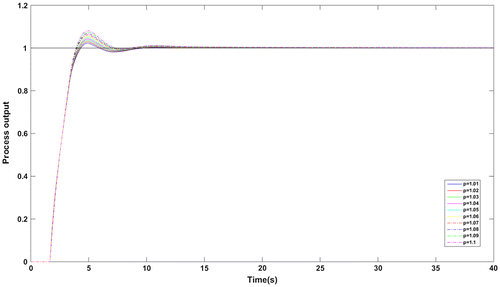
In addition, the servo responses with the proposed method at different values of p are compared and the characteristics are shown in Figure . The ISE and IAE values at each value of p are given in Table which are less than ISE and IAE values used for comparison. Hence, the proposed method has flexibility that the fractional order p can be varied over a range producing lower values of performance metrics. The trend of complementary sensitivity function satisfying the robustness bound is shown in Figure . The characteristics confirm the robust closed loop stability of the simulated system.
Example 3
Consider the second order lag dominant linear process (Dey & Mudi, Citation2009) given by(27)
(27)
The controller designed according to the design rules in Wang et al. (Citation2016) is used for comparison. The controller settings as per their method are: Kc = 1.4247; τi = 1.9924 and τd = 0.498. The proposed controller with the filter parameters γ = 1 and p = 1.01 is(28)
(28)
The set point tracking of closed loop system with a negative step disturbance of magnitude 0.2 applied at t = 20s is shown in Figure while the performance metrics are given in Table . There is negligible overshoot in the response for both the controllers but the error values are lesser with the proposed controller. The similar response holds even after introducing +10% parameter variations in time delay and process gain which is evident from Figure and Table . The Ms values for both methods are in the standard range of 1 to 2 which ensure robust control performance.
The response of closed loop system with added noise is illustrated in Figure . The white noise used has a mean of zero and a variance of 0.0001. The control effort is significantly less with the proposed method against the method used for comparison. The ISE, IAE and TV values for this case are given in Table . The closed loop robust stability satisfying the stability condition in Equation (15) is shown in Figure . It is clear from the magnitude plot that the system is closed loop stable for parametric uncertainties.
Example 4
Consider a higher order process (Astrom & Hagglund, Citation1995):
(29)
(29)
The second order approximated model for the above process is
(30)
(30)
The proposed controller for this process with γ = 2 and p = 1.1 is
(31)
(31)
The settings of the controller used for comparison are: Kc = 0.7086; τi = 3.9987 and τd = 0.7136. Figure shows the servo response for step set point change of unit magnitude and step change in disturbance applied at t = 70s having a magnitude of −0.2. The response for perturbed process model is shown in Figure with + 10% mismatch in time delay and process gain. The performance metrics are provided in Table . Clearly, the proposed controller outperforms the other one used for comparison. There is a drastic reduction in the overshoot.
Figure shows the closed loop response with white noise in the measurement. The TV value of the proposed controller with added noise is low compared to the other value. Table confirms the lower values of ISE, IAE and TV. The Ms value of closed loop system with the proposed controller is 2 where as it is 2.17 for the other method. The value of 2 is the higher limit in the standard Ms range. It means that both the controllers are likely to respond to model uncertainties and their impact could be seen the response.
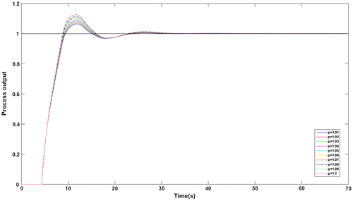
Figure shows the servo response of the process in (30) for the values of p = 1.01, 1.02, … 1.1. The performance metrics ISE and IAE are provided in Table . Better performance is observed at every value of p. Also, the magnitude plot in Figure tells that the complementary sensitivity function with +10% uncertainty in time delay obeys the robust stability condition. Hence, the closed loop system ensures robust and stable performance even with uncertainty in the process parameters.
The effect of fractional filter on the robustness of closed loop control system is explained with the help of parametric uncertainties. A better closed loop response is obtained compared to Wang et al. (Citation2016) method for uncertainty in process gain and time delay for all the four examples which proves that the closed loop system gives robust performance for uncertainties with fractional filter PID controller. Further, the stability of closed loop system with the proposed controller is investigated for parametric uncertainties. It is proved that all the four systems used in the current work are satisfying robust stability condition and the illustrations are shown in Figures , , , . In addition, the closed loop system is robust for noise inputs and the proposed controller successfully attenuates the noise at high frequencies. This is clear from the magnitude of complementary sensitivity function which is approaching zero (Figures , , , ) with increase in frequency for all the four systems.
The proposed method may be extended for finite time systems that lead to finite time control. The stability of the closed loop system with the proposed method may be checked over a finite time for boundedness of the system response (Lazarević, Citation2006; Xu, Zhang, Zhou, & Tong, Citation2017; Xu, Zhou, Fang, Xie, & Tong, Citation2016).
4. Conclusion
A simple IMC-PID controller for SOPTD processes using fractional IMC filter is proposed. Different case studies were analyzed for servo response and regulatory control. It can be concluded from the results that a good closed loop performance is obtained with nominal model and actual model of the process with the proposed controller. The proposed controller resulted in a minimum overshoot in the response in absence of set point weighting. It was also shown that the effort of proposed controller is less for noise corrupted measurements. The robustness for parametric uncertainties is proved with robustness analysis using sensitivity functions. The work is in progress to extend the proposed method for unstable and non-minimum phase systems.
Funding
The authors received no direct funding for this research.
Additional information
Notes on contributors
R. Ranganayakulu
R. Ranganayakulu is a PhD candidate in the Department of Chemical Engineering of National Institute of Technology Warangal, India.
G. Uday Bhaskar Babu
G. Uday Bhaskar Babu has been working as an assistant professor in the Department of Chemical Engineering of National Institute of Technology Warangal, India. He received his PhD degree from IIT Kharagpur in Chemical Engineering. His research interests include Fractional order PID, Model based control, Modeling and Simulation, Nonlinear Control and Process Intensification.
A. Seshagiri Rao
A. Seshagiri Rao has been working as an associate professor in the Department of Chemical Engineering of National Institute of Technology Warangal, India. He received his PhD degree from IIT Madras in Chemical Engineering. His research interests include Process Dynamics and Control, PID Tuning, Time Delay Systems and Waste water treatment.
References
- Astrom, K. J., & Hagglund, T. (1995). PID controllers: Theory, design, and tuning. Research Triangle Park, NC: ISA.
- Chen, D., & Seborg, D. E. (2002). PI/PID controller design based on direct synthesis and disturbance rejection. Industrial & Engineering Chemistry Research, 41, 4807–4822.10.1021/ie010756m
- Dey, C., & Mudi, R. K. (2009). An improved auto-tuning scheme for PID controllers. ISA Transactions, 48, 396–409.10.1016/j.isatra.2009.07.002
- Jeng, J.-C., Tseng, W.-L., & Chiu, M.-S. (2014). A one step tuning method for PID controllers with robustness specification using plant step-response data. Chemical Engineering Research and Design, 92, 545–558.10.1016/j.cherd.2013.09.012
- Lazarević, M. P. (2006). Finite time stability analysis of PDα fractional control of robotic time-delay systems. Mechanics Research Communications, 33, 269–279.10.1016/j.mechrescom.2005.08.010
- Lee, J., Cho, W., & Edgar, T. F. (2013). Simple analytic PID controller tuning rules revisited. Industrial & Engineering Chemistry Research, 53, 5038–5047.
- Lee, Y., Park, S., Lee, M., & Brosilow, C. (1998). PID controller tuning for desired closed-loop responses for SI/SO systems. AIChE Journal, 44, 106–115.10.1002/(ISSN)1547-5905
- Maciejowski, J. M. (1989). Multivariable feedback design, Electronic Systems Engineering Series. Wokingham: Addison-Wesley.
- Madhuranthakam, C., Elkamel, A., & Budman, H. (2008). Optimal tuning of PID controllers for FOPTD, SOPTD and SOPTD with lead processes. Chemical Engineering and Processing: Process Intensification, 47, 251–264.10.1016/j.cep.2006.11.013
- Morari, M., & Zafiriou, E. (1989). Robust process control. Englewood Cliffs, NJ: Prentice Hall.
- Panda, R. C., Yu, C.-C., & Huang, H.-P. (2004). PID tuning rules for SOPDT systems: Review and some new results. ISA Transactions, 43, 283–295.10.1016/S0019-0578(07)60037-8
- Ranganayakulu, R., Uday Bhaskar Babu, G, & Seshagiri Rao, A. S. (2016). A comparative study of fractional order PIλ/PIλDμ tuning rules for stable first order plus time delay processes. Resource Efficient Technologies, 2, S136–S152.10.1016/j.reffit.2016.11.009
- Rao, A. S., Rao, V., & Chidambaram, M. (2009). Direct synthesis-based controller design for integrating processes with time delay. Journal of The Franklin Institute, 346, 38–56.
- Shamsuzzoha, M. (2013). Closed-loop PI/PID controller tuning for stable and integrating process with time delay. Industrial & Engineering Chemistry Research, 52, 12973–12992.10.1021/ie401808 m
- Shamsuzzoha, M. (2015). A unified approach for proportional-integral-derivative controller design for time delay processes. Korean Journal of Chemical Engineering, 32, 583–596.10.1007/s11814-014-0237-6
- Shamsuzzoha, M., & Lee, M. (2007). IMC−PID controller design for improved disturbance rejection of time-delayed processes. Industrial & Engineering Chemistry Research, 46, 2077–2091.10.1021/ie0612360
- Shamsuzzoha, M., & Lee, M. (2008). Design of advanced PID controller for enhanced disturbance rejection of second order processes with time delay. AIChE Journal, 54, 1526–1536.10.1002/(ISSN)1547-5905
- Silva, G. J., Datta, A., & Bhattacharyya, S. P. (2007). PID controllers for time-delay systems. Berlin: Springer Science & Business Media.
- Skogestad, S. (2003). Simple analytic rules for model reduction and PID controller tuning. Journal of Process Control, 13, 291–309.10.1016/S0959-1524(02)00062-8
- Srivastava, S., Misra, A., Thakur, S., & Pandit, V. (2016). An optimal PID controller via LQR for standard second order plus time delay systems. ISA Transactions, 60, 244–253.10.1016/j.isatra.2015.11.020
- Srivastava, S., & Pandit, V. S. (2016). A PI/PID controller for time delay systems with desired closed loop time response and guaranteed gain and phase margins. Journal of Process Control, 37, 70–77.10.1016/j.jprocont.2015.11.001
- Vilanova, R., & Visioli, A. (2012). PID control in the third millennium. London: Springer.10.1007/978-1-4471-2425-2
- Wang, Q., Lu, C., & Pan, W. (2016). IMC PID controller tuning for stable and unstable processes with time delay. Chemical Engineering Research and Design, 105, 120–129.10.1016/j.cherd.2015.11.011
- Weigand, W. A., & Kegerreis, J. E. (1972). Comparison of controller-setting techniques as applied to second-order dead time processes. Industrial & Engineering Chemistry Process Design and Development, 11, 86–90.10.1021/i260041a017
- Xu, Y., Zhang, J., Zhou, W., & Tong, D. (2017). Finite-time bounded synchronization of the growing complex network with nondelayed and delayed coupling. Dynamics in Nature and Society, 2017.,Article ID 6501583, 7 pages. doi:10.1155/2017/6501583
- Xu, Y., Zhou, W., Fang, J. A., Xie, C., & Tong, D. (2016). Finite-time synchronizat-ion of the complex dynamical network with non-derivative and derivative coupling. Neurocomputing, 173, 1356–1361.10.1016/j.neucom.2015.09.008

