 ?Mathematical formulae have been encoded as MathML and are displayed in this HTML version using MathJax in order to improve their display. Uncheck the box to turn MathJax off. This feature requires Javascript. Click on a formula to zoom.
Abstract
A method of the ultrasonic transmission time difference (ToF) flow measurement is the one which is mainly applied to large diameter flow meters by incorporating high power digital signal processing devices. In this paper, we propose a ToF-type ultrasonic water meter which can be applied to small diameter flow meters such as water meters at home. Unlike the existing ToF method, a differential ToF (dToF) algorithm is proposed to calculate the flow rate irrespective of the water temperature. We have also focused on low-power design by minimizing the computational portion of the micro-controller. To do this, a measuring principle using dToF has been implemented with a single front-end chip and a single MCU.
Public Interest Statement
The water meter developed in this paper is a statutory meter employed to measure the amount of tap water used at home and to charge the water bill. Most of the existing water meters are equipped with wings on the flow part where the water passes, and the amount of water used can be measured by observing the number of turns of the wings. In this paper, we apply the method of flow measurement by measuring the transit times of an ultrasonic wave in the upstream and downstream direction. The proposed method relies on measuring the differential time of flight, where it can measure flow rate regardless of sound speed Typically, this kind of method is mainly applied to a large water meter. The proposed method can apply to the small size water meters of 15–25 mm diameter which are mainly used in homes.
1. Introduction
Recently, due to the development of information and communication technologies, Internet of Things (https://en.wikipedia.org/wiki/Internet_of_things)-based smart metering has attracted considerable attention. In the case of water meters, there is an increasing need to implement a smart water meter that improves measurement uncertainty and remote meter reading of water usage. In Korea, most water meters are made with the mechanical structure and are installed outdoors, so that they often break down due to freezing in winter. In particular, as the mechanical water meter rotates the wing with the fluid flow of the tap water, the flow rate is measured by counting the number of rotations. This type of water meter has a large measurement error with a low flow rate.
Water consumption in recent purifiers installed in many homes is about 1~2 LPM (liter per minute), which is 0.06–0.12 m3/h. According to the technical standard (Water Meter Technical Standards, Citation2015) of water meter, this usage belongs to the lower flow rate zone (Q1 ≤ Q ≤ Q2), with the maximum permissible error of ±5% (see Table ). Notice that Q1, Q2, Q3, and Q4 are the minimum flow rate, the transitional flow rate, the permanent flow rate, and the overload flow rate, respectively. The measurement error at such low flow rate can hardly be measured after a certain period of time after installation of the mechanical water meter (Lee, Park, Lee, Park & Rho, Citation2009).
Table 1. Maximum permissible error for each accuracy class according to the flow rate zone
Among the existing mechanical water meters, positive displacement (PD) water meters are known to have a high accuracy of flow rate measurement. As can be seen in Figure , comparing error characteristics between ultrasonic water meter and PD water meter, PD meter (Shen, Citation2015) shows a remarkably low accuracy (on average) of flow rate measurement in the range of 0.10 GPM (gallon per minute, 0.44 m3/h) to 35 GPM (154 m3/h). Specifically, while the measurement accuracy of PD water meter is drastically lowered below 2 GPM (8.8 m3/h), but that of ultrasonic water meter remains almost unchanged. The% registration value, which is the Y-axis in Figure , represents the percentage error of the water meter. It can be calculated as follows:
Figure 1. A comparison of error characteristics between ultrasonic water meter and PD water meter (Shen, Citation2015).
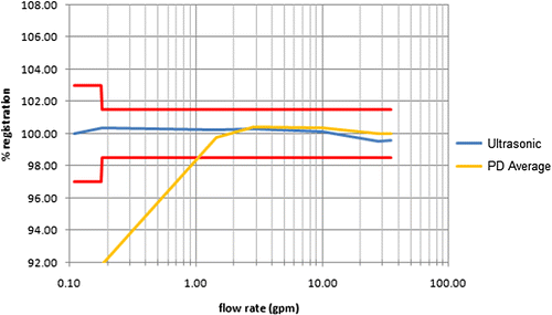
It indicates 100.00 when the measurement from the water meter shows no error. If it is larger than 100, the error is additive, and, when it is smaller than 100, it is subtractive. Said differently, this value represents the error value from the measured reading from the water meter.
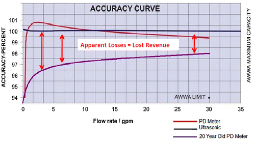
Figure shows the comparison of the error characteristics according to the durability of ultrasonic water meter and PD water meter. Ultrasonic water meters have little or no change over time, whereas 20 year-old PD water meters are out of the permissible error range.
Figure 2. Comparison of durability error characteristics between ultrasonic meter and PD meter (Shen, Citation2015).
Overall, there are two methods of measuring flow rate using ultrasonic wave: the methods of measuring flow rate using Doppler effects (Human Resource Development Institute, Citation2015; Spitzer, Citation1990) and the methods of measuring flow rate by calculating the transmission time difference (ToF) of two ultrasonic waves (Human Resource Development Institute, Citation2015; Lee & Hong, Citation2016; Lee, Lee, & Hong, Citation2015; Spitzer, Citation1990).
The Doppler style ultrasonic flow meters (Shen, Citation2015) measure flow rate by changing the frequency scattered in the ultrasonic wave while bubbles or foreign substances in the fluid flow together with the flow fluid. In the Doppler style flow meters, two ultrasonic transducers are employed in the system. One transmits a continuous ultrasonic wave into the flow. The other transducer receives the ultrasonic wave scattered from suspending particles. The received wave has a frequency shift compared to the transmitted one. This shift is the so-called Doppler frequency shift, which is directly proportional to the flow velocity. Therefore, by detecting the Doppler frequency, one can derive the flow velocity. The flow rate of the pipe liquid is obtained by computing the product of the velocity and the cross-section area of the pipe. This method is mainly used to measure the flow rate of a fluid containing bubbles or foreign matter in the fluid, such as sewage or waste water.
The other ultrasonic method of wave propagation time flow measurement uses two ultrasonic transducers that function as both the ultrasonic transmitter and the receiver. The ultrasonic wave transducers, A and B, are installed at the upstream side and the downstream side at the distance (L) (see Figure ). Of note, they are installed so that to face each other at the slope of θ with respect to the direction of fluid flows to be able to transmit and receive the ultrasonic waves. The flow meter operates by alternately transmitting and receiving a burst of sound energy between the two transducers and measuring the transit time that it takes for sound to travel between the two transducers. The difference in the transit time measured is directly and exactly related to the velocity of the liquid in the pipe.
Figure 3. Ultrasonic wave propagation time flow measurement (Human Resource Development Institute, Citation2015).
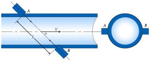
Let C be the ultrasonic wave speed in the liquid and V be the flow velocity averaged over the wave path. If the downstream (A → B) propagation time of the ultrasonic signal is t1 and the upstream (B → A) propagation time of the ultrasonic signal is t2, the propagation time difference of the ultrasonic signal in the fluid can be expressed as shown in Equation (1) (Human Resource Development Institute, Citation2015; Lee et al., Citation2015). Since and
, then it becomes as follows:
(1)
(1)
Since C2 > > V2 cos θ2, the flow velocity V is given by Equation (2):(2)
(2)
Therefore, the flow rate Q can be calculated as Equation (3).(3)
(3)
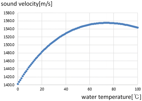
As can be seen from Equation (3), the flow rate Q is proportional to the square of the sound speed (C2). Figure shows that the speed of sound in water is determined from the temperature-dependent equation of Bilaniuk and Wong (Citation1993). In Figure , the Y-axis and the X-axis shows the sound velocity and the water temperature, respectively. At the water temperature 0°C is 1,400 m/s, but accelerates to 1,560 m/s at 70°C. Therefore, correction by water temperature is inevitable in the ultrasonic method of wave propagation time flow measurement.
As explained earlier, ultrasonic water meters have the advantage of being capable of not only low flow measurement, but also of improving the measurement uncertainty. Typically, this method has been mainly applied to a large water meter. In this paper, we will apply the ultrasonic method of differential time-of-flight (dToF) flow measurement, where it can measure flow rate regardless of sound speed. Specifically, our proposed method can apply to the small size water meters of 15–25 mm diameter that are mainly used in homes.
Existing water meters are not able to measure tap water at a low flow rate and, therefore, it cannot be charged as a water bill. However, the dToF-type ultrasound water meter proposed in this paper allows us to reach a smaller minimum detectable flow, as compared to previous techniques, making it possible to manage the leakage. Therefore, the amount of unused tap water can be considerably reduced.
The remainder of this paper is organized as follows. Section 2 overviews related research. We describe a dToF flow measurement algorithm in Section 3. Section 4 shows the test results to validate the proposed method. Finally, conclusions are drawn in Section 5.
2. Related works
2.1. Ultrasonic method of wave ToF flow measurement
The ultrasonic method of wave ToF flow measurement (Human Resource Development Institute, Citation2015; Lee et al., Citation2015; Lee & Hong, Citation2016; Spitzer, Citation1990) is frequently used for industrial flow measurement. It is divided into the time domain method and the frequency domain method.
In the time domain method of ultrasonic ToF flow rate measurement, two ultrasonic transducers are employed in the system. Ultrasonic waves transmitted from one ultrasonic transducer are measured using a signal transmitted to the other ultrasonic transducer through a medium. As shown in Equation (4), the time-varying flow velocity vt is a function of the difference between the downward transmission time Td and the upward transmission time Tu of the ultrasonic wave with respect to the angle θ. Notice that θ is formed between the flow velocity axis and the transmission axis of the ultrasonic wave (Spitzer, Citation1990).(4)
(4)
where D is the diameter of the pipe. The time domain style flow meter has a fast response, because it can measure the flow rate every ultrasonic transmission cycle. The smaller the time resolution, the smaller the flow rate measurement is possible. On the other hand, since the measured flow rate is proportional to the square of the sound speed in the fluid, it sensitively responds to the sound speed. Therefore, when designing the flow meter using the method of ultrasonic ToF measurement in the time domain, it is necessary to correct the sound speed according to the temperature of the fluid.
In the frequency domain method of ultrasonic frequency difference flow measurement two ultrasonic transducers are employed in the system and it consists of a downward ultrasonic loop () in which ultrasonic waves are transmitted in the same direction as the fluid flow and an upward ultrasonic loop (
) in which the ultrasonic waves are transmitted in a direction opposite to the fluid flow. The received wave has a frequency shift comparing with the transmitted one. This shift is the so-called Doppler frequency shift, which is directly proportional to the flow velocity. Therefore, by detecting the Doppler frequency, we are able to derive the average flow velocity
(see Equation (Equation5
(5)
(5) )). The flow rate of the pipe liquid is obtained by computing the product of the velocity and the cross-section area of the pipe. It should be specified that, unlike the time-domain style flow meter, in the Doppler-type flow meter, the sound velocity is not included as a function of the flow rate.
(5)
(5)
2.2. Ultrasonic water meter research trend
The ultrasonic method of wave ToF flow measurement is divided into three major directions. In order to improve the accuracy of the flow measurement, there is a method of measuring the average flow velocity in the pipe according to the change of the flow velocity profile in the pipe when the diameter of the pipe is large. Another method is to measure the average flow rate by installing three or more lines measuring the ultrasonic ToF.
On the other hand, flow measurement methods to measure the flow rate more easily by attaching an ultrasonic transducer to the wall of the pipe are being studied. These methods use the latest digital signal processing technology. In order to apply the method of ultrasonic flow measurement to small diameter pipes, such as water meters in homes, a front-end chip technology for measuring ultrasonic wave transmission time with low-power consumption (Human Resource Development Institute, Citation2015; Lee et al., Citation2015; Lee & Hong, Citation2016)—one of representative approaches—is used. Hamouda, Manck, Hafiane, and Bouguechal (Citation2016) presented a method of measuring the dToF indirectly by computing the phase difference between the steady-state parts of the received signals in the upstream and downstream directions and by using a least-square-sine-fitting technique.
In order to apply the method of the ultrasonic wave transmission time flow measurement to the water meter, the cost aspect and the durability problem should be solved. Unlike industrial flow meters, water meters for home use should be able to operate for extended periods of time without maintenance during the type approval period once installed. Therefore, an ultrasonic water meter must be designed to operate at a low power with a simple structure. This requirement precludes the use of expensive high-power consumption devices, such as digital signal processing devices used in the existing large-diameter ultrasonic flowmeters.
Previous studies on ultrasonic water meters have been limited to areas where water temperature is calibrated to compensate for the sound speed or to the use of large-scale pipelines for the accuracy class 1 water meters with a diameter greater than 40 mm or more. In the present paper, we will design an ultrasonic water meter applying the method of ultrasonic transmission time flow measurement for water meters with small diameter pipe (15–25 mm diameter). On the other hand, an ultrasonic water meter will be implemented using a single front end chip to satisfy the two design constraints—namely, cost and low power consumption.
3. dToF flow measurement
3.1. dToF flow measurement algorithm
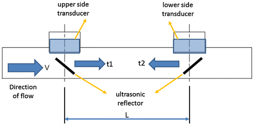
Figure shows the structure of the flow measurement unit with the ultrasonic wave ToF (Human Resource Development Institute, Citation2015; Lee et al., Citation2015; Lee & Hong, Citation2016; Spitzer, Citation1990). It can measure the flow rate of a small diameter pipe such as a water meter in home. Ultrasonic transducers are attached to the upstream pipe (Sensor 1) and downstream pipe (Sensor 2) (see Figure ).
Figure 5. Small-diameter ultrasound transmission time-difference flow measurements (Lee et al., Citation2015).
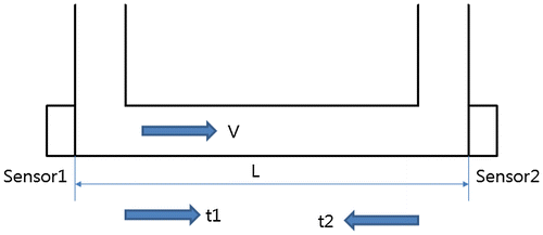
Typically, a diameter of a water meter is relatively small compared to that of an industrial ultrasonic flow meter. As can n be seen in Equation (1), the time difference (Δt = t2 − t1) between the two ultrasonic wave transmissions is also shortened by cos θ2 < cos θ1, 90 > θ2 > θ1 > 0. Therefore, in the case of applying the method of ultrasonic wave ToF flow measurement for a water meter with a small diameter, the ultrasonic transducers are arranged to face each other (see Figure ) (Spitzer, Citation1990).
Notice that, in Figure , the ultrasonic wave is transmitted at a slope θ with respect to the flow velocity. However, in Figure , the ultrasonic wave propagation path and the direction of the fluid flow are designed to be parallel to each other (cos θ = cos 0 = 1).
Let V and L be the flow rate of the fluid and the distance between the two ultrasonic transducers, respectively. Assume that the transmission time of the ultrasonic wave sent from the upstream transducer (Sensor 1) to the downstream transducer (Sensor 2) is t1 and the reverse is t2. The ultrasonic ToF is as follows (see Equation (Equation6(6)
(6) )):
(6)
(6)
Applying C2 > > V2 to simplify Equation (Equation6(6)
(6) ), the flow velocity V becomes equal to Equation (Equation7
(7)
(7) ).
(7)
(7)
Equation (Equation8(8)
(8) ) is an expression for the average value t0 of the ultrasonic transmission time.
(8)
(8)
Since C2 > > V2, the sound velocity C can be summarized as shown in Equation (Equation9(9)
(9) ).
(9)
(9)
The flow velocity V is given by Equation (Equation10(10)
(10) ):
(10)
(10)
where Δt = t2 – t1. Therefore, by accurately measuring the upstream and downstream transit-time t2 and t1, we are able to obtain the flow velocity V. Subsequently, the flow rate Q can be calculated as follows (see Equation (Equation11(11)
(11) )) (https://en.wikipedia.org/wiki/Density):
(11)
(11)
Notice that the sound velocity C is replaced by t0 = (t2 + t1)/2 in Equation (Equation8(8)
(8) ). Thus, the sound velocity term does not appear in the final equations. Therefore, the flow rate can be measured irrespective of the sound velocity C. From Equations (Equation10
(10)
(10) ) and (Equation11
(11)
(11) ), we see that the measurement results, V and Q, are independent of fluid properties, pressure, temperature, pipe materials, etc.
After the ultrasonic wave transmission time t1 and t2 can be measured, the ultrasonic transit-time difference Δt can be calculated and thus the flow Q can be obtained. The method of obtaining the flow rate using Equation (Equation11(11)
(11) ) is called the differential time of flight (dToF) method in order to distinguish it from the ultrasonic wave transit time difference method of Equation (3).
The most important point here is that, unlike the conventional method of ultrasonic wave transit time difference measurement, the dToF type ultrasonic water meter does not need to correct the sound velocity according to the water temperature. As a result, the sound uncertainty due to the water temperature, which has the greatest effect on the measurement uncertainty, is ruled out. Therefore, the measurement uncertainty can be improved by implementing the dToF type ultrasonic water meter.
3.2. Design of the dToF type ultrasonic water meter
3.2.1. The structure of the dToF type ultrasonic water meter
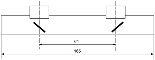
The structure of the dToF-type ultrasonic flow measurement proposed in this paper is shown in Figure . Both a pair of ultrasonic transducers and a pair of ultrasonic reflectors are installed on the upstream and downstream of the pipe through which water flows. the ultrasonic transducers are designed to be less susceptible to fluid flow.
In Figure , the ultrasonic waves emitted from the upper side transducer are reflected at 45° from the upstream reflector and transmitted in the flow direction. The ultrasonic wave of the upper side transducer in the flow direction is reflected at the downstream reflector to be transmitted to the lower side transducer. This downstream ultrasonic wave is transmitted in the flow direction and reaches the lower side transducer after the time t1 elapses. By contrast, the upstream ultrasonic waves are transmitted in the opposite direction of flow and reach the upper side transducer after the time t2 elapses.
3.2.2. A method of measuring the ultrasonic transit time
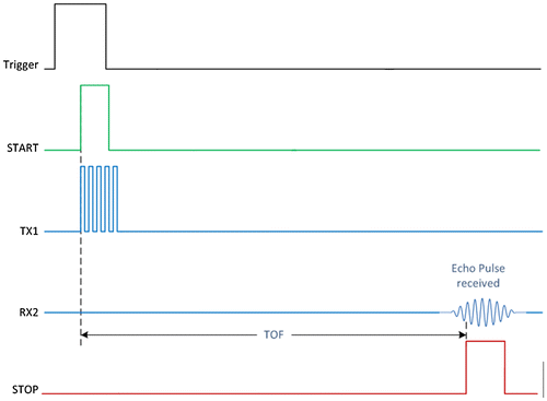
Figure shows the general way to measure the ultrasonic time-of-flight (ToF). When a trigger pulse generated from a control circuit is sent to the driver of the ultrasonic transducer, a voltage is supplied to the piezoelectric element of the ultrasonic transducer to produce the ultrasonic wave TX1. The ultrasonic wave thus produced is transmitted along the ultrasonic medium. When it reaches the counterpart ultrasonic transducer, it is converted into the electric pulse voltage signal by the piezoelectric element. When such a pulse is detected, the time at which the sound wave reaches the opponent can be measured based on the time at which the sound wave is emitted and, thus, the ToF can be known.
Figure 7. The process of measuring the ultrasonic ToF (Texas Instruments, Citation2015).
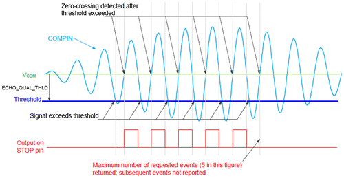
There are a single echo receive mode that observes and measures the received ultrasonic signals one by one and a multiple echo receive mode that observes the entirety of the received ultrasonic waves (Maxim Integrated Products Inc, Citation2015). Since the method of the ultrasonic ToF measurement requires more precise time resolution in order to increase measurement accuracy, we used the single echo receive method (Maxim Integrated Products Inc, Citation2015; Texas Instruments, Citation2015; Time of Flight, Citation2015).
As shown in Figure , the single echo receive mode is a method of detecting the ultrasonic wave transmission time by discriminating each waveform of the sound wave by detecting the zero crossing VCOM after the received sound wave exceeds the threshold voltage. This single echo receive mode has the advantage of being able to measure the ultrasound propagation time with a higher accuracy by precisely setting the end point of the propagation time (Maxim Integrated Products Inc, Citation2015; Texas Instruments, Citation2015).
Figure 8. The operations of the single echo receive mode (Maxim Integrated Products Inc, Citation2015).
3.2.3. A measurement of the ultrasonic dToF
In this paper, Maxim’s MAX35101 front-end chip is used to measure the propagation time of ultrasound wave. The MAX35101 chip integrates an analog circuit that drives an ultrasonic transducer, a device that converts the ultrasonic wave transmission time to a digital value, and programmable arithmetic and control circuitry. In particular, a 2-channel temperature measurement circuit is also incorporated so that it can be applied to the heat meter. The MAX35101 chip has the advantage of being able to design a low-power design, such as the ability to directly connect an ultrasonic transducer directly without external components, thus simplifying the circuit.
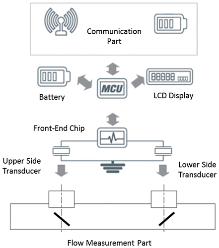
Figure shows the operation flow of the dToF-type ultrasonic water meter. The MAX35101 chip, equivalent to an ultrasonic front-end chip, uses the single echo receive mode for ToF measurements as described in Section 3.2.2. The front-end chip measures the upstream transmission time (t1) and the downstream transmission time (t2) through the upper side transducer and the lower side transducer. The comparator is operated based on the voltage offset in the vicinity of 0 V to detect the waveforms of the received sound waves in the zero-crossing manner. If the detected waveform is a normal waveform, it is determined that the end pulse for measuring the ultrasonic wave propagation time is detected and, in this way, ToF is obtained.
As shown in Figure , the dToF-type water meter directly measures the ultrasound propagation time (ToF) using the low power MAX35101 chip with an average power consumption of just μA. The difference between these two ToF values measured in the two directions is received by the MCU. After that, the dToF is converted to the flow rate to be displayed on the LCD unit.
4. Implementation and field test
4.1. t-factor setting for measuring value compensation
The t-factor using the k-factor used in the turbine flowmeter will be used as a calibration coefficient for both the reference flow unit and the dToF-type water meter to be calibrated. That is, in a flow meter, an eigen value is measured for each individual flow meter and the flow value is displayed on the actual device based on the eigen value. In this paper, we use the t-factor obtained by dividing dToF by the flow rate Q measured by the test flow system (see Equation (12)).(12)
(12)
The t-factor value is stored in each dToF-type water meter and is used to express the flow rate and flow quantity.
In order to convert the measured dToF into the flow rate and the flow quantity, the flow rate correction value of the t-factor is divided into three regions according to the flow quantity.
Calibration values C1, C2, and C3 are designed to be calibrated in the flow measurement ranges Q1 to Q2, Q2 to Q3, and Q3 to Q4, respectively. Notice that Q1 is the minimum flow rate, Q2 is the transitional flow rate, Q3 is the permanent flow rate, and Q4 is the overload flow rate. The dToF-type water meter will be calibrated in each flow range through flow calibration.
4.2. Implementation of the dToF-type water meter
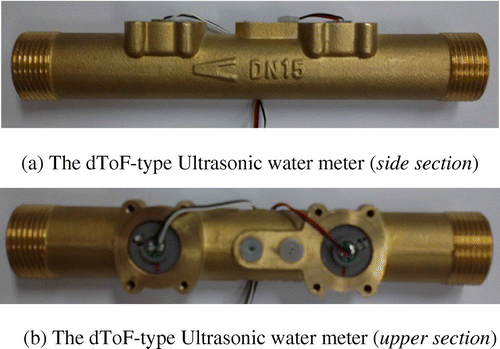
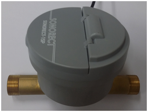
The stm32L162 with a low-power Cortex-M3 is used for the MCU. As explained earlier, the MAX35101 chip is used to measure ToF in the both directions. Figure shows the dToF-type ultrasonic water meter of 15 mm diameter with two ultrasonic transducers. The dimensions of the dToF-type water meter are given in Figure . Figure shows the manufactured dToF-type water meter.
4.3. Tests of the dToF-type water meter
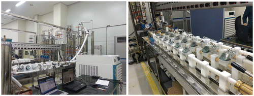
In order to test the measurement accuracy of the dToF-type water meter, a mass measurement method was used. To this end, a test instrument for measuring flow quantity was built using an electronic balance capable of measuring up to 150 kg in 10 g increments. When using the standard method of mass flow measurement, it is necessary to convert the mass of the collected water into a volume. For the development of highly reliable test equipment, such as the calculation of measurement uncertainty, the water density is a function of temperature and, therefore, is converted to 0.9999750 Kg/L at 4°C. However, in this paper, 1 Kg was calculated as 1 L in order to properly limit the scope of this research. Figure shows the test environment configured to measure the performance of the dToF water meter.
Figure 13. The test environment to measure the performance of the dToF-type ultrasonic water meters.
On the other hand, the water temperature of the tester was measured twice: at the beginning and at the end of the test (see Table for the corresponding water temperature values). For reference, the ambient temperature was 20 ± 5°C. Of note, the dToF-type water meter was not evaluated for water temperature. In addition, the calibration of the dToF-type water meter was not performed according to the density of water.
Table 2. Starting point and ending point temperature for each test
The performance test of the dToF-type water meter was carried out for three test sets. The measurement results for these sets are shown in Tables –. The tests were performed at the four flow rate zones, Q1, Q2, Q3 and Q4 at each test. Measurement was repeated three times at each flow rate. Each table summarizes the results of experiments on 12 flow rates. The flow quantity of the dToF type water meter will be measured for three different flow rates for each of the 4 flow rates zones, Q1–Q4. For example, the flow rates of 0.013, 0.015, and 0.012 m3/h that belong to Q1 zone are used for the first 3 data as the designated flow quantities which are represented as Nos. 1, 2, and 3, respectively in each table. Similarly, the designated flow quantities represented as Nos.4–6 belong to Q2 zone.
Table 3. The results for the test set 1 (before calibration)
Table 4. The results for the test set 1 (after calibration)
Table 5. The results for the test set 2 (before calibration)
Table 6. The results for the test set 2 (after calibration)
Table 7. The results for the test set 3 (before calibration)
Table 8. The results for the test set 3 (after calibration)
It should be noted that, in each table, the total collection volume is the actual measured value and the flow quantity indication value is the display value of the dToF type water meter. Thus, the flow quantity error gives the difference between these two values. The t-factor of 60.0000 ns/(m3/h) in the flow range Q1–Q4 was used for the tests. This value is chosen as the mean value. As a result, measurement errors in the range of ±0.17 to ±4.41% occurred in each test set (Tables , , , and Figure (a)). The values of the flow quantity correction factors C1, C2, and C3 of the t-factor were variably applied to 58.0000, 59.0000, and 60.0000 ns/(m3/h), respectively. As can be seen in Figure (b) (see also Tables , , and ), after correction the flow quantity error range is within ±1.0% of the Q2–Q4 range. It is within ±1.5% at some flow rates, although exceeds some ±1.0%.
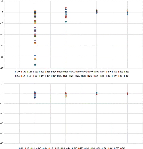
The measurement error was measured for the four zones of flow rates. The measurement error is calculated as [(flow rate indicator value – designated flow rate)/designated flow rate] × 100%. Figure shows the comparison of the measurement errors between the proposed dToF-type ultrasonic water meter and the existing water meter. The results in Figure are quoted from the research report (Lee et al., Citation2009) by Korea Water Resources Corporation. The existing mechanical water meters were actually installed and used. In Figure (a), 13A–13I, 20A–20F and 25A–25D refer to the measurement errors of the existing mechanical water meters of DN15 (13 mm), DN20 (20 mm) and DN25 (25 mm), respectively. On the other hand, 1A–1C, 2A–2C, and 3A–3C are the measurement errors for the dToF-type meter. Figure (b) shows only the results of the dToF-type meters for more clear distinction. As can be seen in Figure , the error of the existing water meter reaches up to 40% in the low flow rate zone Q1.
Figure 14. Comparison of performance before and after calibration (a) error graph before correction and (b) error graph after correction.
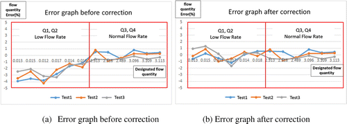
Figure 15. (a) The measurement errors between the existing water meter (Lee et al., Citation2009) and the dToF-type meter and (b) the measurement errors of the dToF-type meter.
5. Conclusion
The method of the ultrasonic ToF flow measurement is mainly applied to a large diameter flow meter by incorporating a high power digital signal processing device. In this paper, we propose the dToF ultrasonic water meter which can be applied to small diameter, such as water meter and consume low power. Unlike the existing ToF method, the proposed dToF algorithm calculates the flow rate irrespective of the water temperature. It is also focused on low-power design by minimizing the computational portion of the microcontroller. To do this, we converted the dToF value to the flow rate and converted it using the t-factor, so that the flow rate could be calculated by a simple arithmetic operation. In the implementation process, the front-end single chip was used to obtain the ultrasonic ToF of two ultrasonic waves to obtain the dToF value.
For the three test sets using the ultrasonic dToF water meter, the flow quantity correction factors C1, C2 and C3 of the t-factor were set to 58.0000, 59.0000, and 60.0000 ns/(m3/h), respectively, and then tested. The results confirmed that the error range of flow quantity was within ±1.5%. However, due to the lack of the testing facilities, we could not evaluate the performance of the dToF-type water meter according to the water temperature change.
It is expected that it can be applied to the flow rate measurement of river flow meter and water channel by supplementing the performance of dToF-type water meter in the future. Techniques applied to the design and implementation of ultrasonic water meters are expected to replace water meters and integrated calorimeters, as well as existing diaphragm gas meters.
Funding
This work is supported by the 2015 Grant of Incheon National University.
Additional information
Notes on contributors
Chul-Ho Lee
Chul-Ho Lee earned his PhD degree from Incheon National University in 2016. In 2012, he acquired the industrial measurement and control professional engineer certification. He worked in Hitrol Co. Ltd. as a CTO. Now he is a CEO of Interface InfoTech Co. Ltd., Korea. His current research interests include process instrumentation in smart factory.
Hye-Kyung Jeon
Hye-Kyung Jeon received her PhD degree from Incheon National University in 2017. In 2007, based on her work experience in hardware control at a communications company, she established Andtech Korea. She holds several patents related to automation. Hers current research interest is RTLS in indoor environment.
Youn-Sik Hong
Youn-Sik Hong received his MS and PhD degrees from Korea Advanced Institute of Science and Technology, in 1985 and 1989, respectively. He is currently Professor at the Department of Computer Science and Engineering at Incheon National University. His current research interests include IoT based application.
References
- Bilaniuk, N., & Wong, G. S. K. (1993). Speed of sound in pure water as a function of temperature. [The Journal of the Acoustical Society of America, 93, 1609–1612, as amended by Bilaniuk, N. & Wong, G. S. K. (1996). Erratum: Speed of sound in pure water as a function of temperature. The Journal of the Acoustical Society of America, 93, 1609–1612 (1993)], The Journal of the Acoustical Society of America, 99(5), 3257.10.1121/1.406819
- Hamouda, A., Manck, O., Hafiane, M. L., & Bouguechal, N.-E. (2016). An enhanced technique for ultrasonic flow metering featuring very low jitter and offset. Sensors, 16(7), 1–12.
- Human Resource Development Institute. (2015). Flowmeter classification and features, Korea Water Resources Corporation (in Korean).
- Lee, C.-H., & Hong, Y.-S. (2016, May). An ultrasonic water meter using differential time-of-flight flow measurement method (Patent No.10-1622566).
- Lee, C.-H., Lee, K.-J., & Hong, Y.-S. (2015, April). A design and implementation of an ultrasonic water meter using differential time-of-flight flow measurement method. Journal of Korean Institute of Information Technology, 13, 17–26.
- Lee, D.-G., Park, J.-Y., Lee, H.-S., Park, T.-J., & Rho, S.-M. (2009). Rate of under-registration and counterplan of flow water. Korea Water Resources Corporation, KWI-GTRC-09-02, Research Report (in Korean).
- Maxim Integrated Products Inc. (2015). MAX35101 time-to-digital converter with analog front-end. Retrieved from https://www.maximintegrated.com/
- Shen, J. (2015, December). Ultrasonic water meter the future for residential water metering. Retrieved from http://www.SpireMT.com
- Spitzer, D. W. (Ed.). (1990, November). Flow measurement practical guides for measurement and control (pp. 415–441). Instrument Society of America.
- Texas Instruments. (2015). TDC1000 ultrasonic sensing analog front end (AFE) data sheet. Retrived from https://www.ti.com/
- Time of Flight. (2015, December). Retrived from https://en.wikipedia.org/wiki/Time_of_flight
- Water Meter Technical Standards. (2015, January). Notice 2014-279. Korean Agency for Technology and Standards.

