
 ?Mathematical formulae have been encoded as MathML and are displayed in this HTML version using MathJax in order to improve their display. Uncheck the box to turn MathJax off. This feature requires Javascript. Click on a formula to zoom.
Abstract
Three coating materials, namely sodium sulphate, 1.6R and 2.35R sodium silicate, were respectively used to coat sodium percarbonate (SPC) particles in a fluidised bed coater to achieve its delayed release in aqueous environment. The size of SPC particles was measured using image analysis. The thickness and porosity of the shell materials were analysed using scanning electron microscopy (SEM) and helium pycnometry respectively. The rates of SPC release from uncoated and the coated particles were measured using an iodide molybdate titration method coupled with UV-vis spectrometry. The results indicate that sodium sulphate coating with an average thickness of 53 ± 9 μm only reduced the release rate of SPC as no delayed release was observed. In contrast, sodium silicate coating generated a significant delayed release. 1.6R sodium silicate coating with a thickness of 109 ± 8 μm delayed the release of SPC by approximate 60 s under a static condition. At the same condition, 2.35R sodium silicate coating with a thickness of 71 ± 10 μm delayed the release by approximately 7 min. When the coated SPC particles immersed in water were shaken using an orbital shaker at 150 rpm, the delayed time was reduced by 50% in comparison with the static condition. The 1.6R sodium silicate shell in solid phase transformed to gel-like structure during dissolution and the hydrodynamic forces generated in the shaker accelerated its dissolution. However, there was no significant change of 2.35R sodium silicate shell when the capsules were immersed in water under the static condition, and they broke into pieces in the shaker. For both 1.6R and 2.35R sodium silicate, the further increase in shell thickness increased their shell porosity, which facilitated the water penetration and thus resulted in no significant benefit to additional delay. Moreover, the thermal stability of SPC after coating was slightly improved and the flowability did not change significantly. This study demonstrates that a significant delay in release of SPC can be achieved using 2.35R sodium silicate as a coating material.
Public Interest Statement
The objective of this study was to prevent bleach in powder detergent with enzyme from dissolving for minutes in aqueous environment, which allows the enzyme to function sufficiently. In order to achieve this, different coating materials, such as sodium sulphate and sodium silicate, were used to create a shell on top of the bleach powders. The characteristics of the modified bleach surface were investigated along with the coated bleach dissolution profile. The results show that sodium silicate prevented bleach from dissolving in water under a static condition up to 7 min. However, the duration of the delay in dissolving was reduced by half when the powders were dissolved in water with stirring. It was also found that the coating did neither deteriorate the ability for the powder to flow nor the bleach thermal stability.
1. Introduction
Sodium percarbonate (SPC), with the formula NaCO3·1.5H2O2, is a peroxide based oxidizing agent, which has drawn significant attentions over the recent years as an environment-friendly bleach in the detergent industry (Bracken & Tietz, Citation2005; McKillop & Sanderson, Citation1995; Tredwin, Naik, Lewis, & Scully, Citation2006), e.g. as a component of washing powder, cosmetic and toothpaste. It is characterized by low cost, good solubility in water and rapid liberation of hydrogen peroxide as active bleaching ingredient. However, SPC is a strong oxidant and it is incompatible with some other ingredients in aqueous solution, e.g. enzymes and perfumes. Once used with enzymes in a commercial composition, e.g. washing powder, enzymes may be deactivated by hydrogen peroxide in aqueous solution; therefore the mutual effectiveness of both the components can be deteriorated. Consequently, delaying the release of sodium percarbonate allows the enzymes to perform at maximum effectiveness before being deactivated in presence of hydrogen peroxide.
Encapsulation/coating technologies are widely used for the purpose of controlled release of active ingredients. By enclosing an active ingredient inside a selected shell material, the former can be protected by the shell and the desirable release profiles may be achieved by choosing an appropriate shell material with desirable structure. During coating process, a core of particulate materials ranging from micrometres to millimetres is covered by a layer of coating material. For wet coating, the coating material is dissolved or suspended in an easily evaporable solvent, which is progressively introduced into an enclosed pulverization system, e.g. fluidised bed coater (Teunou & Poncelet, Citation2002), spouted bed coater (Sutanto, Epstein, & Grace, Citation1985), and rotating drum (Degreve, Baeyes, van de Vvelden, & De Laet, Citation2006), by compressed air where the core particles can be coated. The solvent is evaporated leaving behind a solidified layer of coating material surrounding the particles.
The use of appropriate water soluble coating materials for coating of bleach materials is certainly one of the most promising, albeit challenging, strategies to achieve controlled release of peroxide based bleach. Previously, water soluble polymers such as polyethylence glycol (PEG) were used as coating materials to improve the stability of sodium percarbonate (US Patent No. 5374368A, Citation1994). However, the interaction between H2O2 and PEG inevitably led to loss of the active ingredient (Chiou et al., Citation2004; Tchuenbou-Magaia, Gwyer, Young, & Zhang, Citation2014). Recently, it has been reported that coating of peroxide based bleach powder using xanthan gum (XG) as inner layer and polyvinyl acetate (PVAc) as outer layer improved its long-term stability (Puga, Gracia-Valls, Fernandez-Prieto, Smets, & York, Citation2014). However, the carriers were not designed to achieve delayed release of the peroxide based bleach. Sodium sulphate is widely used as filler in powdered laundry detergents. A variety of salts, including sodium sulphate and magnesium sulphate, have been used to coat SPC to improve its storage stability in a humid atmosphere (US Patent No. 2380620A, Citation1945; US Patent No. 3951838, Citation1976), however, the benefit proved to be limited. Sodium silicate is also an important component of powered detergent, and it can soften water by forming precipitates that can be easily rinsed away. Moreover, all silicates have excellent buffering action against acidic compounds, which is important, because most soils in laundering processes are acidic. Silicates can also inhibit the corrosion of stainless steel and aluminium by synthetic detergents and complex phosphates. There have been reports in patents on using sodium silicate to coat SPC powders to control its release rate in aqueous environment (Patent No. WO 199500255A1, Citation1995; Patent No. EP0623553A1, Citation1994). It has been found that the increase in SiO2:Na2O ratio in sodium silicate and coating/core mass ratio delivered a longer release delay of the coated SPC (Patent No. WO 199704555A1, Citation1997; Patent No. EP 1572852A1, Citation2005). However, little is known about the coating structure and how it affects the diffusion/dissolution of the SPC. Theoretically, the dissolution time of coated SPC can be extended when higher concentration and higher SiO2:Na2O ratio in sodium silicate is used as shell material, but such shell may be satisfactorily dissolved in washing liquid, resulting in a grey colored clothing. Such insoluble ingredients can also lead to undesirable deposits on the washing machine (Patent No. EP 1572852A1, Citation2005).
In this work, sodium sulphate and sodium silicate with relatively low SiO2:Na2O ratios (1.6 and 2.35) were used as coating materials of SPC particles in a fluidised bed coater. The aim of this study is to understand how different shell materials with various structure and thickness can affect the release of SPC in aqueous environment in order to achieve its delayed release in washing process. The thickness and porosity of the shell materials were characterised using scanning electron microscopy (SEM) and helium pycnometry, respectively. The release profiles of coated SPC in de-ionised water were measured using an iodide molybdate titration method coupled with UV-vis spectrometry. The effects of shell thickness and porosity of the abovementioned coating materials on the release profile of SPC, thermal stability and flowability of the coated particles were investigated.
2. Materials and methods
Sodium percarbonate (concentration >85 wt.%) was purchased from Bio Aquatek Ltd, UK. Sodium sulphate anhydrous (analytical reagent grade) was purchased from Fish Scientific Ltd, UK. 1.6R and 2.35R sodium silicate solution, concentration of 40 wt.% and density of 2.4 g cm−3, was provided by P&G Technical Centres Ltd, Newcastle, UK. Potassium iodide (BioUltra, ≥99.5%), Ammonium molybdate tetrahydrate (ACS reagent, 81.0–83.0% MoO3 basis), Potassium hydrogen phthalate (BioXtra, ≥99.95%), PERDROGEN™ 30% H2O2 (w/w), and Sodium hydroxide (anhydrous, ACS reagent, ≥97%) were purchased from Sigma-Aldrich, UK.
2.1. Sample preparation
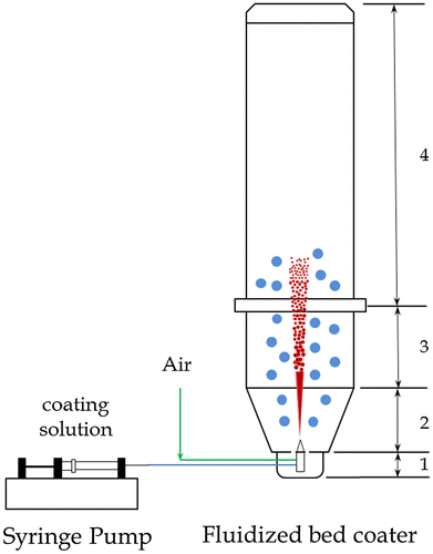
A Glatt® mini fluidised bed coater with bottom spray apparatus (Glatt, Germany) was used to coat 30 g of SPC particles with diameters of 355–500 μm with either sodium sulphate and sodium silicate. There are mainly four parts of the fluidised bed coater from bottom up: lower plenum, product container, fluidised bed zone, and filter house as shown in Figure . The atomising nozzle was located at the centre of the lower plenum with a diameter of 0.5 mm. The coating solution was introduced into the nozzle using a syringe pump. The coating operating conditions were pressure of 5 bar, temperature of 40°C, compressed air flow rate of 30 m3 h−1, atomising air flow rate of 0.5 m3 h−1, coating solution injection rate of 300 μL min−1 for sodium sulphate and 100 μL min−1 for sodium silicate, respectively.
Figure 1. Sketch of the fluidized bed coating process.
Before the coating process, coating solutions were prepared. Sodium sulphate solution was prepared by dissolving sodium sulphate (15 or 30 g) into 100 mL of de-ionised water. 20 wt.% 1.6R and 2.35R sodium silicate solution were prepared by diluting the 40 wt.% solution with the same volume of de-ionised water. 40 and 80 mL of such 20 wt.% solution were used for the coating, respectively. All uncoated and coated samples were placed in an environmental chamber at a fixed temperature of 30°C and relative humidity of 30% for 24 h before their various properties were characterised as follows.
2.2. Characterization of particle morphology, structure and size
3D morphology of coated SPC particles was imaged using Skyscan 1172 X-ray microtomograph (Bruker, Belgium). The cross-sectional image was recorded by a TM3030 tabletop scanning electron microscope with a high sensitivity four-segment semiconductor BSE detector (Hitachi, Japan), operated at an accelerating voltage of 15 kV and magnification of 250. The densities of uncoated and coated SPC were measured by a helium pycnometer (AccuPyc 1330 Micromeritics, USA). The size distribution of the SPC particles, before and after coating, was measured by a QICPIC image analysis system (Sympatec GmbH System-Partikel-Technik, Germany).
2.3. Measurement of dissolution profiles of SPC
Optical microscopy (Leica DMRBE, Leica Mikroskpie & Systeme GmbH – Wetzlar, Germany) was used to observe the dissolution profiles of particles immersed into de-ionised water. In this case, one single particle was placed into a cavity of a microscope slide, followed by adding several drops of de-ionised water onto the cavity to ensure the particle was fully immersed. Timing was started as soon as the water droplets contacted the particle. Then the images of single uncoated and coated particles were recorded, respectively.
2.4. Measurement of release profiles of SPC
Two standard solutions were prepared in advance. Solution A was prepared by dissolving 33.0 g of Potassium iodide, 1.0 g of Sodium hydroxide and 0.1 g of Ammonium molybdate tetrahydrate in 500 mL of de-ionised water. After preparation, solution A was kept in the dark to prevent possible oxidation of I- by light. Solution B was prepared by dissolving 10.0 g of Potassium hydrogen phthalate in 500 mL de-ionised water.
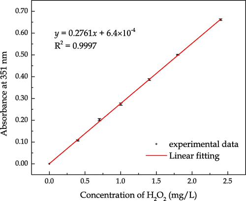
Standard curve was plotted before the release measurement was undertaken. Serial dilutions were prepared by diluting a certain volume of 30% H2O2 into 10 mL of de-ionized water, which were then mixed with 300 μL of solution A and 300 μL of solution B in a UV cuvette. Control experiment was carried out by mixing 10 mL of de-ionized water with 300 μL of solutions A and B. After mixing and incubation of the solution containing H2O2 with a given concentration for 5 min, the absorbance at 351 nm against the control was observed. The chemical reactions between the hydrogen peroxide and the prepared solutions are shown in Equations (1) and (2), in which iodide is oxidized to iodine in the presence of a molybdate catalyst. has a maximum absorbance at 351 nm and the linear standard absorbance curve is plotted in Figure .
(1)
(1)
(2)
(2)
Figure 2. Standard curve of the absorbance at 351 nm vs. hydrogen peroxide concentration.
The hydrogen peroxide release profiles in de-ionised water were studied using an orbital shaker (OM501, Denley, UK) with a rotating speed of 150 rpm at room temperature (20 ± 3°C). 50 mg of uncoated or coated SPC particles were put into 250 mL of de-ionised water in a bottle, 300 μL of sample was withdrawn every 30 s from the bottle and transferred into a tube where each sample was diluted with 10 mL of water. In the meanwhile, the same amount of de-ionised water was added back into the bottle. After fully mixed with the aid of a vortex mixer, 300 μL of the diluted sample was mixed with 300 μL of solution A and 300 μL of solution B in a UV cuvette. After mixing and incubation for 5 min, the absorbance at 351 nm was detected using a UV/Vis spectrophotometer (Cecil CE2021, Cecil Instrument, UK) based on the pre-calculated calibration curve.
2.5. Characterization of coating solution properties
The surface tension of the coating solutions was measured by a Processor Tensiometer K100 (KRÜSS GmbH, Germany) using Wilhelmy plate method. The contact angle of coating solutions on the surface of SPC substrates was measured using a Drop Shape Analyzer DSA30S (KRÜSS GmbH, Germany). Solution viscosity was measured using a Discovery HR-1 hybrid rheometer (Malvern Instruments Ltd, UK) with a 60 mm in diameter cone and plate geometry.
2.6. Characterization of thermal decomposition
Thermal decomposition of the samples was recorded using simultaneous thermal analysis (TG-DSC; STA449 F3 Jupiter® – NETZSCH analyzing & testing). Each sample (20 mg weighted in 6.7 mmϕ × 2.6 mm a platinum crucible) was heated at a heating rate of 5°C min−1 in flowing N2 (100 cm3 min−1) as protection for recording TG-DSC curves.
2.7. Characterization of flowability
The flowability of the powders was quantified by using a small automatic ring shear cell tester (RST-XS, Dietmar-schulze, Germany) at a compression load of 20 MPa and expressed by a flow factor index, ffc. This index is a function of the consolidation stress and unconfined yield strength of the sample.
3. Results and discussion
3.1. Particle characterization
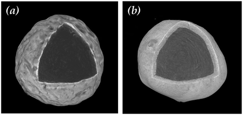
Figure shows the three-dimensional microtomography of a SPC particle coated with sodium sulphate and sodium silicate respectively. It is clear that the surface was rough although a nearly spherical shape was retained. The SPC particle was fully coated by a shell with homogenous thickness. The sodium sulphate shell seems thinner and more compact than the sodium silicate shell as some air pockets were observed in the sodium silicate shell, resulting in a more porous shell structure.
Figure 3. Three dimensional microtomography of a single SPC particle (a) coated with sodium sulphate (coating/core ratio = 50 wt.%) and (b) coated with 1.6R sodium silicate (coating/core ratio = 27 wt.%).
The morphology of the cross-sections of sodium sulphate and sodium silicate coated SPC particles are shown in Figure . It reveals that the SPC core was surrounded by the coating materials with a relative uniform shell thickness. The Sauter mean diameter (D32) of the uncoated particles is shown in Table , respectively. The D32 values in Table were obtained by averaging the data of five measurements. The D32 of uncoated SPC particles was 443 ± 3 μm. The average thickness of the sodium sulphate shell varied from approximately 37 ± 4 to 53 ± 9 μm as the coating/core ratio increased from 50 to 100 wt.%. It was also found that as the coating/core ratio increased from 27 to 53 wt.%, 1.6R sodium silicate shell thickness increased from 72 ± 6 to 109 ± 8 μm and 2.35R sodium silicate shell from 71 ± 10 to 123 ± 9 μm.
Figure 4. Scanning electron microscopy (SEM) micrograph of the cross-section of a single SPC particle (a) coated with sodium sulphate (coating/core ratio = 50 wt.%) and (b) 1.6R sodium silicate (coating/core ratio = 27 wt.%).
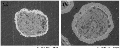
Table 1. Physical and structural properties of sodium sulphate and sodium silicate coated SPC particles
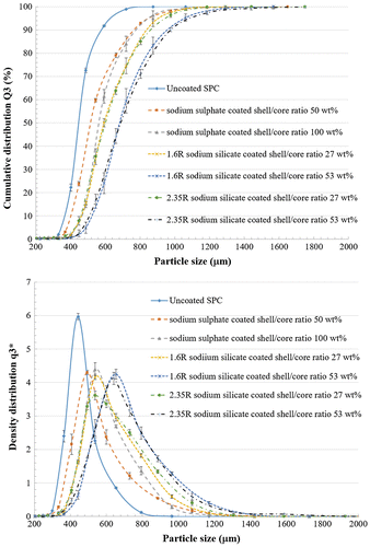
The particle size distributions, including cumulative distribution and density distribution, of uncoated and coated SPC are shown in Figure . The cumulative distribution Q3 is known as percentage undersize. For a given particle size, the Q3(x) represents the percentage of the particles finer than x. The distribution density (log.) represents the number of particles in different size range. The mode particle size is represented by the highest density. In Figure , a monomodal distribution is observed as only one peak is displayed. Both Q3 and
plots show a movement to the larger particle size range. It is clear that the mean size of coated particles was significantly bigger than that of non-coated ones, as expected.
Figure 5. Cumulative distribution Q3 and density distribution of uncoated and coated SPC particles.
As shown in Table , an increase in particle specific density was obtained for SPC coated with sodium sulphate in comparison with uncoated SPC. On the contrary, the density of SPC coated with sodium silicate decreased, especially for the larger amount of sodium silicate used as coating material. Due to the fact that both the densities of sodium sulphate (2.66 g cm−3) and sodium silicate (2.4 g cm−3) are larger than that of SPC (2.1 g cm−3) [18], the decrease in particle density after coating indicates a porous shell surrounding the core particles.
The porosity of the sodium silicate shell can be calculated using the following equation:(3)
(3)
where ρcore, ρshell and are the density of the uncoated core, shell material and coated particle, respectively.
and
is the volume of the uncoated and coated particles, respectively. The details are shown in Appendix A.
It is shown in Table that the sodium sulphate shell was relatively compact and the sodium silicate shell was more porous than the sodium sulphate shell. As a consequence of increasing amount of coating materials, the porosity of sodium silicate shell increased more significantly than that of the sodium sulphate shell. The uniform and almost non-porous sodium sulphate shell indicates that the coating droplets spread evenly over the core particle surface and the dried coating remained attached to the core particle as small patches. The more porous sodium silicate shell may be explained by the larger contact angle on the SPC substrate and higher viscosity of the coating solution (Table ). Larger contact angle indicates a worse wettability of SPC surface by the coating solution. Viscosity causes the coating fluid to resist deformation, tending to prevent its breakup and leading to larger droplet size. Droplet sizes were theoretically calculated by substituting required parameters, e.g. surface tension, density and viscosity, into the following empirical equation for estimating typical size of droplets generated from a nozzel of a given diameter (Rajan & Pandit, Citation2001):(4)
(4)
Table 2. Properties of the coating solutions
where η is the liquid viscosity, σ is the surface tension, ρ is the density, Q is the volumetric flow rate.
The estimated droplet sizes for different coating solutions are given in Table , which increases in the following sequence: 15 wt.% sodium sulphate <30 wt.% sodium sulphate <20 wt.% 1.6R sodium silicate <20 wt.% 2.35R sodium silicate. The relatively large and highly viscous droplets need more time and energy to spread on the surface of the core particles. Thus, the air in the fluidised bed may be trapped in the shell forming from these droplets during the coating process.
3.2. Particle dissolution
3.2.1. Dissolution profiles under static condition
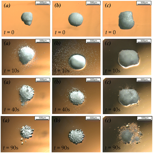
The microscopic images of the particle dissolution in de-ionised water under static condition, including uncoated SPC particles, sodium sulphate coated at 50 wt.% coating/core ratio and 1.6R sodium silicate coated at 27 wt.% coating/core ratio, are shown in Figure . It is obvious that the uncoated SPC particle immediately dissolved in water and released oxygen bubbles surrounding the particle. After SPC was coated by sodium sulphate, no bubble was observed on the particle surface during the first 10 s, indicating the decelerated dissolution rate of SPC core protected by the sodium sulphate shell. However, a significant dissolution of the sodium sulphate coated SPC particle was observed after the first 10 s, resulting in bubbles occurring on its surface. In contrast, the dissolution of 1.6R sodium silicate coated SPC particle was almost prohibited during the first 40 s, after which the silicate shell was cracked by the oxygen bubble from the weakest part. Then, the silicate shell dissolved in water and transformed to a gel-like film surrounding the SPC particle, which provided further protection of the SPC particle from dissolution. Unlike the solid silicate shell, the dissolution rate of SPC particle was slowed down rather than completely prohibited when the gel was formed.
Figure 6. Microscopy images of the dissolution of (a) uncoated (b) sodium sulphate coated SPC at coating/core ratio of 50 wt.% and (c) 1.6R sodium silicate coated SPC at coating/core ratio of 27 wt.% under static condition.
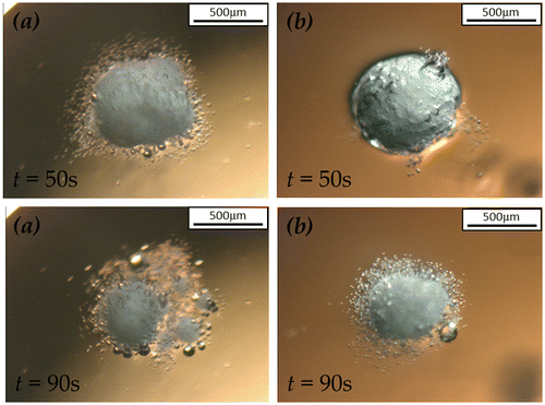
The effect of 1.6R sodium silicate shell thickness on the SPC particle dissolution profile is shown in Figure . In this case, SPC particles coated by sodium silicate solution at the coating/core ratios of 27 and 53 wt.% were compared. The shell thickness was 72 ± 6 and 109 ± 8 μm, respectively. As indicated, the thicker sodium silicate shell was capable of delaying the release of SPC by 50 s, approximately 10 s longer than the thinner shell, in de-ionised water under static condition. The thicker sodium silicate shell of the particles resulted in more significantly delayed release of SPC in the absence of hydrodynamic force.
Figure 7. Microscopy images of the dissolution of 1.6R sodium silicate coated SPC particles at coating/core ratio of (a) 27 wt.% and (b) 53 wt.% under static condition.
The microscopic dissolution profiles of 2.35R sodium silicate coated SPC particles at the coating/core ratios of 13 and 27 wt.% in de-ionised water under static condition are shown in Figure . As can been seen, the dissolution of sodium silicate coated SPC at 13 wt.% coating/core ratio started immediately when in contact with water. A large proportion of core was dissolved through the big holes appearing on the shell at about 90 s. This indicates that 13 wt.% coating/core ratio of 2.35R sodium silicate led to an incomplete coating (partial coating) on the core surface, which is undesired for the controlled release. On the other hand, as shown in Figure (b), the 27 wt.% coating/core ratio of 2.35R sodium silicate exhibited significantly improved delay of release of SPC. Only a few of small bubbles were observed at 1 min, indicating water penetration through the shell and dissolution of the core particle at the interface between the shell and core. However, due to the apparently stable and strong 2.35R sodium silicate shell, the generated bubbles slowly released through the pores of the shell without breaking it. As a result, the physical structure of 2.35R silicate shell remained before the core completely dissolved. Similar to 1.6R sodium silicate shell, the increase in coating/core ratio of 2.35R sodium silicate from 27 to 53 wt.% also prolonged the delay of SPC release. On average, using 27 and 53 wt.% coating/core ratio 2.35R sodium silicate as coating materials delayed the SPC release by 5 and 7 min, respectively. Such delay may allow the enzymes in detergent to fully function before they come in contact with SPC in a washing process.
Figure 8. Microscopy images of the dissolution of 2.35R sodium silicate coated SPC particles at coating/core ratio of (a) 13 wt.% and (b) 27 wt.% under static condition.
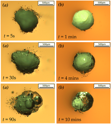
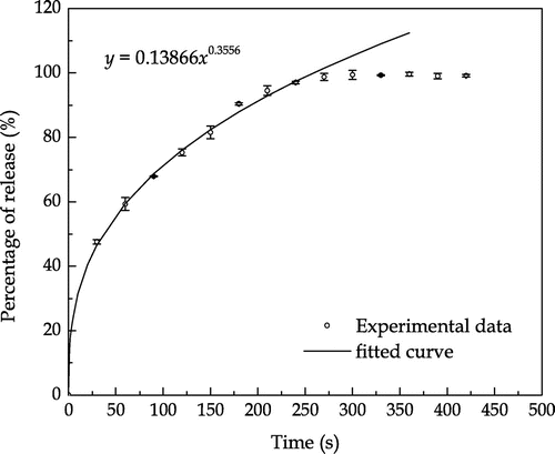
Figure 9. Experimental and fitted curves of the uncoated SPC particles release profile obtained under the dynamic condition. The correlation coefficient R2 = 0.98.
3.2.2. Dissolution profiles under dynamic condition
The hydrogen peroxide release profile of the uncoated SPC particles in de-ionised water under the shaking condition is shown in Figure . The cumulative release increases with time until approximately 300 s when the release reaches 100%. The release data was fitted using a semi-empirical equation as follows:(4)
(4)
which is similar to the analytical equation for describing diffusion from a hollow sphere (Crank, Citation1975) where the exponent is 0.5 for the initial period of release.
As indicated in Figure , the fitted curve shows good consistency with the experimental data in the first 250 s, within which the percentage of release increased following a power law as the time increased.
The hydrogen peroxide release profiles of uncoated and sodium sulphate coated SPC particles in de-ionised water under the dynamic condition are shown in Figure . The percentage of release shown in Figure was obtained by dividing the absorbance at 351 nm measured at a fixed time with the absorbance at the end of the measurement (12 min in this study). It is clear that the uncoated SPC required at least 5 min to completely dissolve under the given condition. The sodium sulphate shell decelerated the release rate of hydrogen peroxide and thicker shell led to more significant deceleration.
Figure 10. Release profiles of uncoated and sodium sulphate coated SPC particles.
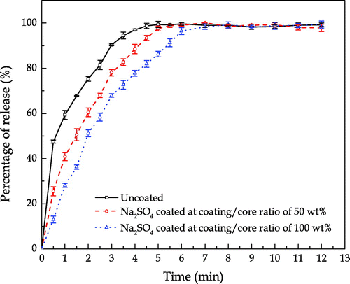
Figure shows the hydrogen peroxide release profiles of uncoated SPC, 1.6R and 2.35R sodium silicate coated SPC particles with different coating/core ratios. The operating condition for the measurement of hydrogen peroxide release was the same as that in Figure . In comparison with the sulphate shells, a delay by approximate 30 s in the release of hydrogen peroxide was observed with 1.6R sodium silicate shells. After 30 s, the sodium silicate coated SPC started to dissolve and the thicker silicate shell resulted in slight improvement of the delay of the hydrogen peroxide release. This can be explained by the change of shell structure during the dissolution. The dissolution of 1.6R sodium silicate transferred the solid shell to a gel-like film surrounding the SPC particles as shown in Figures and . Due to the impact of hydrodynamic force generated, the dissolution rate of silicate gel was accelerated, which weakened the silicate shell’s initial structure. In addition, as water molecules could penetrate through the porous shell, oxygen was generated at the surface of core, which further disintegrated the shell structure due to the increased internal pressure.
Figure 11. Release profiles of uncoated and sodium silicate coated SPC particles. Notes: From left to right: □—Uncoated SPC; ○—1.6R sodium silicate coated SPC at coating/core ratio of 27 wt.%; △—1.6R sodium silicate coated SPC at coating/core ratio of 53 wt.%; ☆—2.35R sodium silicate coated SPC at coating/core ratio of 13 wt.%; ▽—2.35R sodium silicate coated SPC at coating/core ratio of 27 wt.%; ◇—2.35R sodium silicate coated SPC at coating/core ratio of 53 wt.%.
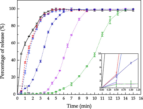
In contrast, 2.35R sodium silicate shell offered a longer delay of the release. Delays by approximate 3.5 and 4.5 min were respectively observed for 2.35R sodium silicate at the coating/core ratios of 27 and 53 wt.%. This may be explained by the chemical and physical properties of 2.35R sodium silicate in comparison with those of 1.6R sodium silicate. It is known that the various grades of sodium silicate are characterised by their mass ratio of silicon dioxide (SiO2) to sodium oxide (Na2O). 2.35R sodium silicate means the SiO2:Na2O mass ratio is 2.35, in which more silicon dioxide is included than 1.6R sodium silicate. The OH groups on the surface of SiO2 are the main centres of adsorption of water molecules. When sodium silicate in solid phase is formed at the surface of SPC particles during the coating process, silanol groups are formed simultaneously in terms of either condensation-polymerization of Si(OH)4 or rehydroxylation of thermally dehydroxylated SiO2 in aqueous atmosphere (Zhuravlev, Citation1993). The silanol groups may condense to form siloxane bridges. Moreover, the concentration of OH group on the SiO2 surface monotonically decreases at elevating temperature. At an insufficient OH group concentration, the predominance of siloxane bridges on the silicon dioxide surface results in a hydrophobic property (Legrand et al., Citation1990). The higher SiO2:Na2O ratio sodium silicate may lead to more hydrophobicity of the shells. Thus, 2.35R sodium silicate exhibits better water proof performance than the 1.6R sodium silicate.
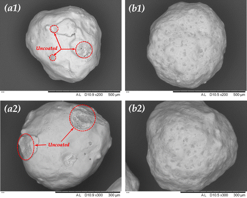
In Figure , the dissolution profile of 2.35R sodium silicate coated SPC at 13 wt.% coating/core ratio differs from the other 2.35R sodium silicate coated particles, which shows no delay of release in the first few minutes. These particles even dissolved faster than the 1.6R sodium silicate coated particles in the first half minute. This might be due to the incomplete coverage of the coating material on the surface of core particles. Smaller droplet size of coating solution is responsible for more homogenous and compact coating (Dennison et al., Citation2016; Saleh, Cherif, & Hemati, Citation1999). As shown in Figure , a certain surface area of the SPC particle was not covered by 2.35R sodium silicate at the coating/core ratio of 13 wt.% and droplet size of 64 μm. Dissolution could rapidly occur at the uncovered part, which is consistent with the microscopic observation shown in Figure . When hydrodynamic forces are applied, the dissolution rate of the partial coated particles also depends on the mechanical strength of the shells. Because the apparent dissolution rate is a function of contact area, if the shell would not dissolve or be peeled off from the core, it could wrap the core and reduce its contact area to water. This helps to explain the observation shown in Figure , where the dissolution of 2.35R sodium silicate coated SPC at 13 wt.% coating/core ratio is slower than the uncoated and 1.6R sodium silicate coated SPC particles during the first few minutes after 30 s.
Figure 12. Scanning electron microscopy (SEM) micrograph of the top view of single 2.35R sodium silicate coated SPC particle at coating/core ratio of (a) 13 wt.% and (b) 27 wt.%.
It is speculated that the physical strength of 2.35R sodium silicate shell was higher than the 1.6R sodium silicate shell, which is based on the dissolution profiles as shown in Figure . Unlike the 1.6R sodium silicate shell, under static condition, the physical structure of 2.35R silicate shell could remain after about 4 min of dissolution. The SPC core completely dissolved at about 14 min, leaving a shell with hollow structure at the end. On the contrary, under the dynamic condition, as shown in Figure , the 2.35R silicate shells cracked and broke into small pieces without turning into gel-like structure after several minutes. It is believed that the 2.35R sodium silicate shells yielded a certain mechanical strength, which is capable of providing protection of SPC core thus reducing its surface area exposed to water in case of partial coating, e. g. 2.35R sodium silicate at 13 wt.% coating/core ratio. Therefore, in comparison with 1.6R sodium silicate, relative slow dissolution rates are observed in Figure for varying amounts of 2.35R sodium silicate as shell. The slowest release for the investigated conditions was obtained when 2.35R sodium silicate was used to coat SPC at a coating/core ratio of 53 wt.%, and it took approximately 14 min for all the SPC to be released. Corresponding to this, the time taken for 50% of the SPC to be released (T50) was 10.3 min, which is longer than desirable T50 of 3–8 min for bleach used in detergent with surfactant, enzyme and suds suppressing agent as proposed in WO 1995028473 A1. The release rate of SPC can thus be tuned to meet specific requirements for given industrial applications.
3.3. Particle thermal decomposition
TG-DSC curves for the thermal decomposition of uncoated, sodium sulphate coated and sodium silicate coated SPC particles are shown in Figure . Good thermal stability of both the uncoated and sodium sulphate coated SPC particles was observed for temperatures lower than 130°C, which is in a good agreement with the work of Wada and Koga (Wada & Koga, Kinetics and mechanism of the thermal decomposition of sodium percarbonate: Role of the surface product layer, Citation2013). As a consequence of the increase in temperature, the descending TG thermal curves indicate weight losses occurred. As reported by Wada et al. (Wada, Nakano, & Koga, Multistep kinetic behaviour of the thermal decomposition of granular sodium percarbonate: Hindrance effect of the outer surface layer, Citation2015), the thermal decomposition process of SPC consists of a two-step reaction, namely, the dissociation of H2O2 (g) from SPC and the decomposition of H2O2 (g) into H2O (g) and O2 (g). Two obvious weight loss processes were respectively observed at 100 and 150°C for the sodium silicate coated SPC particles, indicating the decomposition of the sodium silicate shell and SPC itself, respectively.
Figure 13. TG-DSC curves for the thermal decomposition of uncoated SPC (solid line), sodium sulphate coated SPC (dash line) and sodium silicate coated SPC (dot line) at heating rate of 5°C min−1 in flowing N2 at 100 cm3 min−1
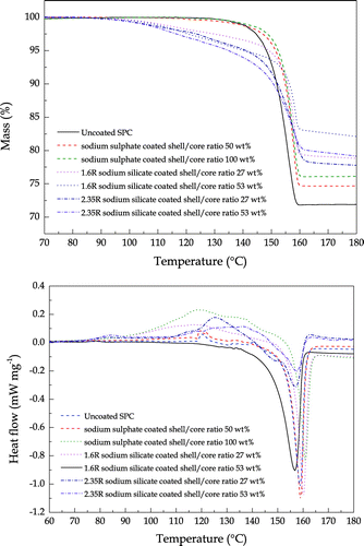
It was found that both the sodium sulphate and sodium silicate shells slightly shift the thermal decomposition temperature of SPC toward a higher temperature. Especially for the sodium silicate shell, the hydration water in the silicate shell is firstly released at approximately 100°C, then the remaining shell to some extent protects the SPC core by impeding its mass-loss process. This may be explained by the speculation that at the reaction interface where the diffusional removal of the evolved gases is impeded by the shell, the thermal decomposition reaction is decelerated due to the chemical accumulation established at the interface. Note that the thicker shell, for both the sodium sulphate and sodium silicate, did not provide extra protection of the SPC core during the thermal decomposition process. As previously discussed, more porous shells are prone to form in thicker shells. The extra protection initiated by a thicker shell is offset due to the increase in porosity as the pores inside the shell provide a pathway of the evolved gases.
3.4. Particle flowability
The flowability of the uncoated and coated SPC particles is shown in Table . The flow index of the powders according to the Jenike classification (Teunou, Fitzpatrick, & Synnott, Characterisation of food powder flowability, Citation1999) represents the following properties: ffc < 1 (not flowing), 1 < ffc < 2 (very cohesive), 2 < ffc < 4 (cohesive), 4 < ffc < 10 (easy-flowing) and ffc > 10 (free flowing). Despite the flow index decreased after coating, the particles still exhibited a free-flowing property.
Table 3. Flowability of uncoated and coated SPC particles
4. Conclusions
For the purpose of delaying the release of SPC from particles in aqueous environment, three materials, i.e. sodium sulphate, 1.6R and 2.35R sodium silicates, were used to coat the SPC particles in a fluidised bed coater. It was found that the fluidised bed coater was capable of producing very homogenous coating on the core particles, especially when a small amount of coating materials with low viscosity was used.
Results showed that sodium sulphate coating, rather than delayed, slowed down the release of SPC in aqueous environment. On the contrary, both 1.6R sodium silicate and 2.35R sodium silicate coatings delayed the release up to 7 min, depending on the coating material, coating thickness and whether the particles were exposed to static or dynamic aqueous environment. However, the benefit of increasing the coating thickness became less significant as the thickness was increased since its porosity also increased.
Both sodium sulphate and sodium silicate shells slightly shifted the thermal decomposition temperature of SPC toward a higher temperature. However, the thicker shells did not provide significantly extra protection of the SPC core during the thermal decomposition process due to the increase in shell porosity. The coating had a very limited effect on the flowability, and the particles before and after coating exhibited a free-flowing property.
Overall, the achieved longest delay in the release of SPC using a coating of 2.35R sodium silicate whose shell structure remained for minutes during the dissolution process and the flexible ways to control the release rate of SPC are advantageous, and may be exploited for various industrial applications.
Funding
The authors gratefully acknowledge the financial support from Technology and Science Board, UK [grant number TS/L003473/1].
Additional information
Notes on contributors
Lei Xing
Lei Xing received his BE degree from Inner Mongolia University of Technology in 2005 and ME degree from Taiyuan University of Technology in 2008 in China. He then worked as a lecturer in Inner Mongolia University of Technology for two years. After that he moved to the UK for a postgraduate study and obtained his PhD degree in 2014. He joined the University of Birmingham as a postdoc research fellow from 2014 to 2016. Recently, he has been working as a professor in the Institute of Green Chemistry and Chemical Engineering, Jiangsu University, China. His research interests include electrochemical devices modelling, meso-scale fluid flow, particle coating, dissolution and controlled release. He has published 1 book, 1 book chapter, and more than 20 journal and conference papers. He has also made several oral presentations at international conferences.
References
- Bertsch-Frank, B., Bewersdorf, M., Klasen, C., Lieser, T., Muller, K., & Rollmann, J. (1995). Patent No. WO 199500255A1. Frankfurt am Main, DE: United States Patent.
- Baillely, G. M., Hall, R. G., & Vermote, C. L. M. (1997). Patent No. EP0753565 A2. Cincinnati, OH: European Patent Register.
- Bracken, J., & Tietz, D. (2005). Analysis of OxiClean: An Interesting Comparison of Percarbonate Stain Removers. Journal of Chemical Education, 82, 762–764.10.1021/ed082p762
- Chiou, S. C., Chang, C. F., Chang, C. Y., Wu, Y. P., Chang, C. T., Li, Y. S., & Chen, Y. H. (2004). Mineralization of polyethylene glycol in aqueous solution by hydrogen peroxide with basic oxygen furnace slag. Environmental Technology, 25, 1357–1365.10.1080/09593332508618468
- Crank, J. (1975). The mathematics of diffusion. OXford: Clarendon Press.
- Degreve, J., Baeyes, J., van de Vvelden, M., & De Laet, S. (2006). Spray-agglomeration of NPK-fertilizer in a rotating drum granulator. Powder Technology, 163, 188–195.10.1016/j.powtec.2006.01.019
- Dennison, T. J., Smith, J., Hofmann, M. P., Bland, C. E., Badhan, R. K., & Al-Khattawi, A. (2016). Design of experiments to study the impact of process parameters on droplet size and development of non-invasive imaging techniques in tablet coating. PLOS ONE, 11(8), e0157267.10.1371/journal.pone.0157267
- Hauschild, J. P. (1994). US Patent No. 5374368A. Bridgewater, NJ: United States Patent.
- Javawant, M. D., & Yates, P. C. (1976). US Patent No. 3951838. Wilmington, DE: United States Patent.
- Jeffrey, J., Park, J. S., Baillely, G. M. (1995). WO 1995028473 A1. Cincinnati, OH: European Patent Office.
- Jigstam, M., & Lagnemo, H. (2005). Patent No. EP 1572852A1. Cincinnati, OH: European Patent Register.
- Kokubo, J., Hiro, Y., Hisano, K., & Watanabe, S. (1994). Patent No. EP0623553A1. The Hague: European Patent Register.
- Legrand, A. P., Hommel, H., Tuel, A., Vidal, A., Balard, H., & Papirer, E. (1990). Hydroxyls of silica powders. Advances in Colloid and Interface Science, 33, 91–330.10.1016/0001-8686(90)80027-W
- McKillop, A., & Sanderson, W. (1995). Sodium perborate and sodium percarbonate: Cheap, safe and versatile oxidising agents for organic synthesis. Tetrahedron, 51, 6145–6166.10.1016/0040-4020(95)00304-Q
- Oswald, H. W. (1945). US Patent No. 2380620A. Runcorn: United States Patent.
- Puga, A. V., Gracia-Valls, R., Fernandez-Prieto, S., Smets, J., & York, D. (2014). Dual Xanthan Gum/Poly(vinyl acetate) or Alkyl-Functionalized Poly(vinyl alcohol) films as models for advanced coatings. Journal of Applied Polymer Science. doi:10.1002/APP.40870
- Rajan, R., & Pandit, A. B. (2001). Correlations to predict droplet size in ultrasonic atomisation. Ultrasonics, 39, 235–255.10.1016/S0041-624X(01)00054-3
- Saleh, K., Cherif, R., & Hemati, M. (1999). An experimental study of fluidized-bed coating: Influence of operating conditions on growth rate and mechanism. Advanced Powder Technology, 10, 255–277.10.1163/156855299X00334
- Sutanto, W., Epstein, N., & Grace, J. R. (1985). Hydrodynamics of spout-fluid beds. Powder Technology, 44, 205–212.10.1016/0032-5910(85)85001-4
- Tchuenbou-Magaia, F. L., Gwyer, J., Young, N., & Zhang, Z. (2014). Designing sustained release encapsulates loaded with water soluble oxidant: Carbamide peroxide. Chicago, IL: CRS Annual Meeting.
- Teunou, E., Fitzpatrick, J. J., & Synnott, E. (1999). Characterisation of food powder flowability. Journal of Food Engineering, 39, 31–37.10.1016/S0260-8774(98)00140-X
- Teunou, E., & Poncelet, D. (2002). Batch and continuous fluid bed coating - review and state of the art. Journal of Food Engineering, 53, 325–340.10.1016/S0260-8774(01)00173-X
- Tredwin, C., Naik, S., Lewis, N., & Scully, C. (2006). Hydrogen peroxide tooth-whitening (bleaching) products: Review of adverse effects and safety issues. British Dental Journal, 200, 371–376.10.1038/sj.bdj.4813423
- Wada, T., & Koga, N. (2013). Kinetics and mechanism of the thermal decomposition of sodium percarbonate: Role of the surface product layer. The Journal of Physical Chemistry A, 117, 1880–1889.10.1021/jp3123924
- Wada, T., Nakano, M., & Koga, N. (2015). Multistep kinetic behavior of the thermal decomposition of granular sodium percarbonate: Hindrance effect of the outer surface layer. The Journal of Physical Chemistry A, 119, 9749–9760.10.1021/acs.jpca.5b07042
- Zhuravlev, L. T. (1993). Surface characterization of amorphous silica – a review of work from the former USSR. Colloids and Surfaces A: Physicochemical and Engineering Aspects, 74, 71–90.10.1016/0927-7757(93)80399-Y
Appendix A
Assume the core is non-porous and the shell is porous with a porosity of ɛ. After coating, the density of the coated particle can be calculated as:(A1)
(A1)
where ρcore, ρshell, and ρair are the density of the uncoated core, shell material, coated particle, and air respectively.
,
and
are the volume of the uncoated core, shell and coated particles, respectively. The shell volume is given by:
(A2)
(A2)
Because the density of air is much smaller than the densities of core and shell materials, the third term of the numerator in Equation (A1) can be omitted. Thus Equation (A1) becomes:(A3)
(A3)
In which, the volumes of particles can be calculated by relating to their diameters as:(A4)
(A4)
where, d0 and is the diameter of uncoated and coated particles.