 ?Mathematical formulae have been encoded as MathML and are displayed in this HTML version using MathJax in order to improve their display. Uncheck the box to turn MathJax off. This feature requires Javascript. Click on a formula to zoom.
Abstract
This paper presents guidelines to develop the Maximum Power Point Tracking controller, as developed in the automotive and aeronautical applications, this by following the V-cycle development process, which means that our controller will be validated by using Model In the Loop/ Software In the Loop/Processor In the Loop tests. In order to have the possibility of integrating the MPPT embedded software in automotive and aeronautical areas, and on the other hand to propose a low-cost option to test the hardware implementation of the MPPT algorithm. Therefore, a modified variable step Incremental Conductance algorithm is proposed in this study, which can reduce the steady-state oscillations and increase the tracking speed under sudden irradiance variation. Then, the Model-based design of the modified algorithm is developed and connected to the plant model (photovoltaic panel and Boost converter). Next, the system model is tested and validated by using Model In the Loop process. After that, the software of this algorithm is automatically generated for the host computer using embedded coder tool, and this software is connected to the plant model and tested using Software in the Loop process in the host computer. Finally, the software is generated from the MPPT model for the STM32F4 discovery board in order to create the Processor In the Loop block, which will be run in the STM32F4 discovery board, and the plant model will be simulated in the host computer, and the ST-LINK communication is used in order to connect the host computer and the embedded board.
Public Interest Statement
This work develops a modified Maximum Power Point Tracking controller as the automotive and aeronautical applications are developed, and by following a V-cycle development process, that means that our controller will be validated using Model in the loop/Software in the loop/ Processor in the loop tests. This works can be used as a reference to integrate photovoltaic energy in automotive or aeronautical fields. In addition, Processor in the loop test presented in this work, can be used a low-cost solution to test the hardware implementation of MPPT algorithm.
1. Introduction
Optimizing the power withdrawn from PV panel is always a challenge for researchers. Therefore, many solutions have been proposed in order to improve the PV energy efficiency especially the following ones:
| • | Solar tracker, where the solar panels are fixed on a structure that moves according to the position of the sun (Barker, Neber, & Lee, Citation2013; Fathabadi, Citation2016a; Poulek, Khudysh, & Libra, Citation2016; Visconti, Costantini, Orlando, Lay-Ekuakille, & Cavalera, Citation2015; Wu, Zhang, & Wang, Citation2016); | ||||
| • | Automatic cleaning system for the photovoltaic panel (Kawamoto & Shibata, Citation2015); | ||||
| • | MPPT from which we control the PV panel in order to get its maximum of power (Eze, Iloanusi, Eze, & Osuagwu, Citation2017; Nayak, Mohapatra, & Mohanty, Citation2017; Saharia, Manas, & Talukdar, Citation2016; Verma, Nema, Shandilya, & Dash, Citation2016). | ||||
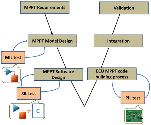
However, the hardware implementation of these solutions is not easy, especially the MPPT algorithm, even if the MPPT algorithm is implemented by simulation tools like Simulink or PSIM. But, once we start the hardware implementation of MPPT algorithm in digital devices like microcontroller, microprocessor, DSP and FPGA, several problems can occur due to either the mismatches which can appear between the software and the requirements during the development process, or the fact that all the components used are real (PV panel, DC/DC converter, sensors, actuators and microcontroller). Hence when a bug occurs, it is difficult to know exactly the responsible component of this bug. That can increase the time spent in debugging runtime errors. Therefore in other fields, like Automotive and Aeronautic, the software can be generated from the model tested and validated by simulation, and there are different steps between simulation and hardware implementation step. For instance, generally the automotive and aeronautical embedded software follows the V-cycle development process (Dubois, Peraldi-Frati, & Lakhal, Citation2010; Moy, Ledinot, Delseny, Wiels, & Monate, Citation2013), and as shown in Figure , there are three tests mostly used in these areas, MIL, SIL and PIL tests, and in each one, there is an aim to be checked. For MIL, the aim is to check the model developed from the algorithm requirements, in other words, check that the model is in accordance with the algorithm requirements. For SIL, the aim is to check that the software generated from the model in the host computer. For PIL, the aim is to check that the software generated from the model in the embedded target. That can avoid redundant testing activities while improving software quality.
Note that the development cycle is recommended by the norm applied in the aeronautical area, like DO-178C norm (DO-178C, Citation2011; Moy et al., Citation2013), it recommends that the embedded software follows development cycle in order to achieve the objective of this norm, which is producing software in accordance with its requirements (MPPT algorithm requirements in our case). Since good processes make good software, a V-cycle development process is suitable due to its accuracy, because it contains a verification process for each design process. As a result, an error may be detected through several verification activities. Consequently, we can remove a maximum of errors. If the objective is not attained, the software will not be certified (DO-178C, Citation2011; Moy et al., Citation2013); hence the software cannot be integrated in the aircraft. Therefore, when PV energy is used in hybrid electric aircraft, the MIL/SIL/PIL tests are suitable to be made by following the V-cycle development process for the MPPT software, that to check if this software is in accordance with its requirements and contribute to certify it. In addition, the tools used to generate and validate the software must be qualified by DO-178C norm (DO-178C, Citation2011). Therefore Matlab/Simulink is used in this work as a qualified tool (Mathworks, Citation2016a).
Moreover, the choice of such MPPT algorithm is based on its tracking speed, steady-state performance and its ability to be implemented in embedded board ensuring high robustness. Hence, the most used are P&O and INC algorithms; in particular, the INC algorithm which is a new version of P&O, and it is used extensively due to its ability to reduce the steady-state oscillations (Sivakumar, Kader, Kaliavaradhan, & Arutchelvi, Citation2015). Subsequently, in order to improve its efficiency, a variable step-size is used (Motahhir, El Ghzizal, Sebti, & Derouich, Citation2016). However, this variable step can show poor performance in case of sudden irradiance variation. In addition, it can increase steady-state power oscillations (Zakzouk, Elsaharty, Abdelsalam, Helal, & Williams, Citation2016). Therefore, this work proposes a modified variable step-size.
On the other hand, the MPPT implementation step is required to test our algorithm under controlled conditions of temperature and irradiation. PV panels are unable to reproduce power desired by the tester due to the randomly fluctuating atmospheric conditions. Therefore, solar panel simulators are frequently used in place of actual PV panels (Ahmed & Salam, Citation2016). Kok Soon Tey and Saad Mekhilef have used an Agilent solar array simulator for implementing a Modified incremental conductance MPPT algorithm (Tey & Mekhilef, Citation2014). Also, PV emulators by using programmable DC power supply are already proposed (Kadri et al., Citation2012; Zhou, Holland, & Igic, Citation2014). However, solar array simulators or programmable DC power supply are expensive instruments and they are not always affordable. Therefore, the PIL test can be used as a low-cost solution to test the hardware implementation of the MPPT algorithm under different conditions of irradiation and temperature.
Hence in this work, a modified variable step INC algorithm is used, which can reduce the steady-state oscillations and improve the tracking speed under sudden irradiance variation. In addition, this work aims to develop the proposed MPPT technique by following the V-cycle development process and using MIL/SIL/PIL tests, that for two reasons. Firstly, in order to take advantage of these kinds of tests and to provide a low-cost solution for testing MPPT. Secondly, to have a possibility of integrating the MPPT embedded software in automotive and aeronautical fields. And as a result, use it for example in hybrid electric vehicle or aircraft.
This paper is organized as follows: after introduction, section two provides a general recall on a PV panel and a Boost converter, next a modified variable step is proposed in this section. Finally, section three focuses on the implementation of modified variable step INC algorithm and test it by using MIL/SIL/PIL techniques.
2. PV system
2.1. PV panel model
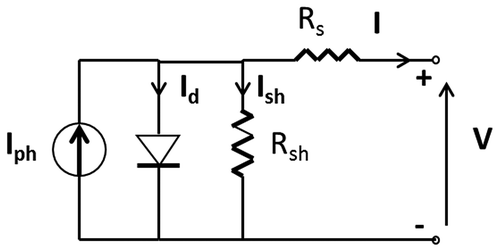
A PV panel is a component that can convert a solar energy into direct current electricity by using semiconducting materials that exhibit the PV effect. In order to model mathematically a PV panel, we derive the fundamental equation from the equivalent circuit of the PV panel shown in Figure (Motahhir, Chalh, El Ghzizal, Sebti, & Derouich, Citation2017; Villalva, Gazoli, & Filho, Citation2009).
The current generated by the panel can be given as (Motahhir et al., Citation2017; Villalva et al., Citation2009):(1)
(1)
where:(2)
(2)
(3)
(3)
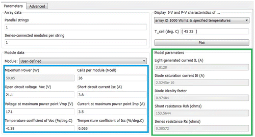
In this study, the MSX-60 panel is used, and as shown in Table , manufacturers of PV panel offer only some parameters. Hence, several parameters mandatory for modeling PV panel are missed in the manufacturers’ specification, namely the diode saturation current, the light-generated current, the diode ideality factor and the series and shunt resistances. Therefore, many researchers have worked on the adjustment of theses parameters (Ishaque & Salam, Citation2011; Villalva et al., Citation2009), actually thanks to Mathworks that provides in the new version of Simulink (2016) a tool (PV Array) that can help us to extract these parameters (Mathworks, Citation2016b). Therefore, as shown in Figure , once the parameters mentioned in manufacturer specification are provided to this tool, the latter adjusts and displays the missing parameters.
Table 1. Specifications of Solarex MSX-60 PV panel at STC
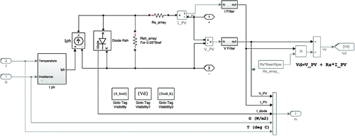
Based on the Equations (1), (2) and (3), Figure shows the model developed by Matlab/Simulink tool.
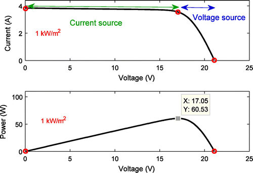
Figure presents the I–V and P–V curves obtained by the PV Panel Simulink model and as presented in P–V curve, the point where the power drawn from the panel is the highest is called MPP. This characteristic is depending on the temperature and solar irradiation. Also, the own characteristic of the load is usually different from the MPP. Therefore, the MPPT controller is used in order to remove this mismatch between the load and MPP. Which in turn, to operate the PV panel at this point, the Boost converter controlled by the MPPT algorithm is inserted between the PV panel and the load (Glasner & Appelbaum, Citation1996).
2.2. Boost converter
It should be mentioned that the PV energy is not like a conventional energy source because in a conventional energy source, energy which is not delivered to the load it is not consumed and remains in the source, in PV energy source the energy is wasted since it is available for free. Thus by using the Boost converter, current flows constantly into the input port due the use of parallel switch in its topology, however by using Buck converter for example, there are times where current is not flowing into the input port due the use of series switch, which in turn the energy is not delivered to the load when the switch is open and the energy is wasted since it is available for free. Hence, in PV system, the energy efficiency of the Boost converter may be higher than of the Buck converter (Glasner & Appelbaum, Citation1996).
The Boost converter is required to convert DC voltage (V) to another DC voltage (Vo). As shown in Figure , this converter contains a MOSFET switch, which is controlled by PWM signal. Once the switch is ON, the inductor stores energy from the PV module, Moreover, the reverse biased diode detaches the output from the PV generator and output capacitor provides current to the load. However, if the switch is OFF, the inductor is in a discharge state and the forward biased diode connects the output to PV generator. The PV panel voltage and inductor voltage (discharging state) contribute together for the output voltage; therefore, it is always greater than input voltage (Abusorrah et al., Citation2013; Du & Lu, Citation2011; Fathabadi, Citation2016b; Glasner & Appelbaum, Citation1996; Motahhir, El Ghzizal, Sebti, & Derouich, Citation2015; Santos, Antunes, Chehab, & Cruz, Citation2006).
This converter operates by the following equations (Mohan & Undeland, Citation2007):(4)
(4)
(5)
(5)
The input capacitor value can be designed as below (Mohan & Undeland, Citation2007):(6)
(6)
The inductor value can be calculated as mentioned by Equation (7) (Mohan & Undeland, Citation2007), where r is between [0.3, 0.5] (Sanjaya, Citation2006):
(7)
(7)
The minimum value of the output capacitor can be designed as mentioned by Equation (8) (Mohan & Undeland, Citation2007):(8)
(8)
The duty cycle for the peak power transfer at STC is determined by using Equation (9):(9)
(9)
The parameters of the designed Boost converter used in this work are given in Table :
Table 2. Parameters of the boost converter
2.3. Modified variable step incremental conductance algorithm
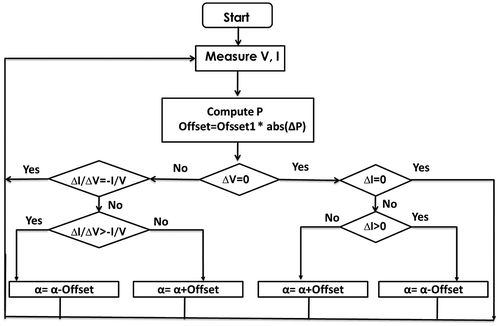
As shown in Figure , the used MPPT algorithm is based on the conventional INC algorithm, in which the controller gauges incremental variations in PV current and voltage to predict the impact of the command (Radjai, Rahmani, Mekhilef, & Gaubert, Citation2014; Soon & Mekhilef, Citation2015). This algorithm needs more calculation but can follow changing conditions faster than P&O method (Soon & Mekhilef, Citation2015). However, like P&O algorithm, INC can produce oscillations in the output power since the oscillations in steady-state are proportional to the step-size (Offset). If the step-size is high, then oscillations are high. Otherwise, the oscillations would be low, but the variation of the duty cycle (α) will be very low; this may slow down the tracking process. As a result, by using fixed step-size a trade-off problem exists between faster response and steady-state oscillations. Hence to improve MPPT algorithm performance a variable step-size was used as mentioned by (10) (Motahhir et al., Citation2016), where Ofsset0 is the scaling factor.(10)
(10)
However, this conventional variable step-size shown in (8) depends on the change of the PV power and PV voltage. Consequently, this conventional step-size can increase steady-state power oscillations. In addition, it can show poor performance in case of sudden irradiance variation. We can explain that as follows:
2.3.1. In case of stable irradiance
As shown in Figure , in the area near to MPP and in voltage source region, the PV voltage change (ΔV) is very low; as a result, the ΔP/ΔV steps will be large. Therefore, these large step-sizes can increase steady-state power oscillations; as a result, the algorithm efficiency is decreased.
2.3.2. In case of irradiance variation
The conventional variable step can decrease the performance in case of sudden irradiance variation. As shown in Figure , during the variation in irradiance, the PV voltage change (ΔV) is very low whereas there is a significant PV power variation (ΔP) because the change in irradiance affects PV current instead of PV voltage. Consequently, the ΔP/ΔV steps will be large. Therefore, this moves the operating point far away from the new MPP, which in turn increases the time to reach the new MPP. Therefore, the algorithm efficiency is decreased.
In order to overcome this problem, a modified variable step-size is used in this work, which depends only on the PV power change (ΔP) (11):(11)
(11)
Where Ofsset1 is the scaling factor which is adjusted to compromise between the response time and reducing the steady-state oscillations.
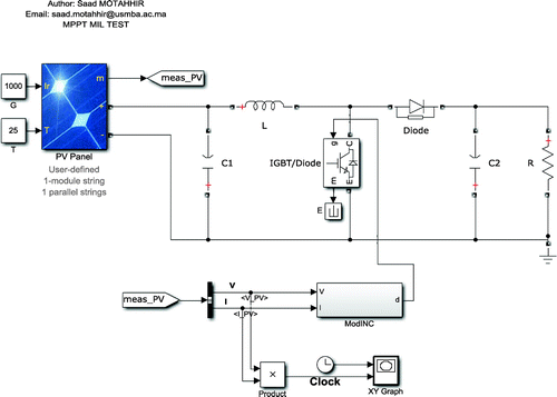
As well, the Figure describes the PV system implementing the modified variable step-size INC algorithm using Model-Based Design in order to control the Boost converter.
3. MIL/SIL/PIL tests for MPPT algorithm
3.1. Model in the loop
The INC algorithm with modified variable step is modeled and it is connected to the plant model (PV panel and Boost converter). In this step, the MPPT model is tested in a simulation environment (Simulink) and this process is called MIL test. This means that the controller model and the plant model are simulated on the host computer without any real hardware components (Bringmann & Krämer, Citation2008).
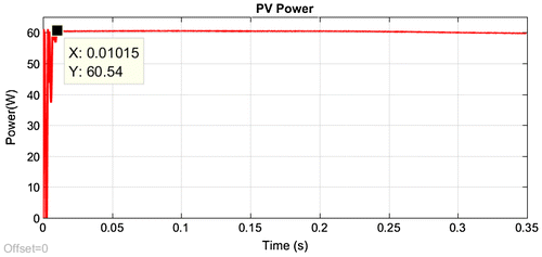
The result obtained using MIL test under STC is presented in Figure , and as shown in the steady-state, the PV power is equal to 60.54 W, which is the maximum power of the Solarex MSX-60 panel under STC (1,000 W/m² and 25°C). In addition, as shown the variable step-size used gives a fast response without steady-state oscillations.
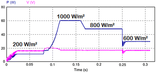
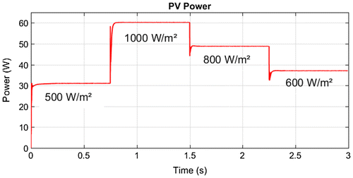
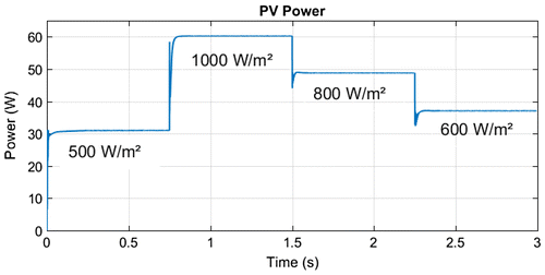
Secondly, the MIL test is made under sudden irradiance variation, Firstly, the solar irradiation is suddenly modified from 500 to 1,000 W/m², and next from 1,000 to 800 W/m², and finally from 800 to 600 W/m². Figure presents the test result, and as shown the modified algorithm presents faster response during irradiance changes and the steady-state oscillations are almost neglected.
3.2. Software in the loop
Once the model of the modified INC algorithm is validated using MIL method, the SIL method is the next step in order to check the code automatically generated from the MPPT model. SIL test means that the code is generated from the model for x86 target using Microsoft Windows SDK (Software Development Kit) and embedded coder tools as shown in Figure . That to test this code on the host computer without any hardware (Bringmann & Krämer, Citation2008).
As shown in Figure , in order to generate the SIL block, the option “Create Software-in-the-loop (SIL) block” must be selected before building the modified variable step INC model.
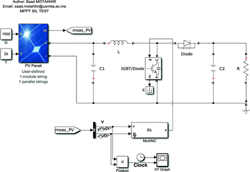
As displayed in Figure , the code generated is implemented in the S-function block provided by Simulink, and this block is connected to the plant model (PV panel and the Boost).
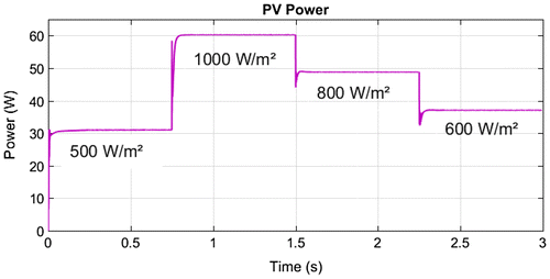
The result obtained using SIL test is presented in Figure . The result of this test is compared with that of the MIL test. And as shown, the SIL result is in accordance with MIL result.
3.3. Processor in the loop
Once the software of the modified variable step INC algorithm is validated using SIL method, the PIL method is the next step in order to check the automatically generated embedded software and to test the implementation of our MPPT algorithm.
PIL test means that the code is generated from the model for the embedded target by using the target’s compiler and embedded coder tool, in order to load and run the generated hex file on the embedded board. However, the plant model is simulated on the host computer. And they are connected by USB cable. The PIL test process is a fundamental step of the development cycle to check that the comportment of the deployment code covers the requirements of our algorithm (Bringmann & Krämer, Citation2008; Hu, Zeng, Yao, & Tang, Citation2010).
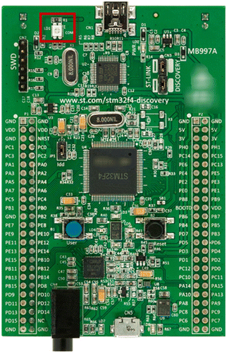
Figure presents the embedded board used in this test which is STMicroelectronics STM32F4 Discovery board. The microcontroller integrated in this board is STM32F407VG from ST Microelectronics. This microcontroller contains a 32-bit ARM Cortex-M4F CPU with 1Mbyte flash memory, 192Kbytes SRAM and a maximum clock frequency of 168 MHz, and with FPU (Floating Point Unit) and DSP instructions. It provides also communication interfaces like CAN/USB (Von Maurich & Güneysu, Citation2014). So the more calculation needed by the modified INC algorithm can be covered by this board due to the hardware resources that contains.
So the hex file is generated from the Simulink model for this board by using its tool chain (GNU Tools for ARM Embedded Processors) and embedded coder tools.
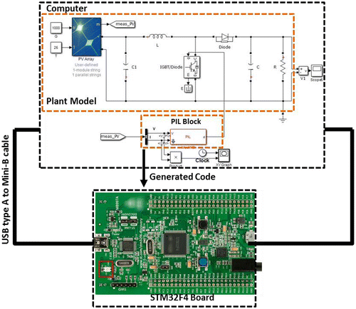
Since the PIL test means that the MPPT software will be run on the STM32F4 Discovery board, and the plant model will be simulated on the host computer, the communication interface between the two parts is needed. Therefore, the ST-LINK communication is used as shown in Figure , which does not require any additional cables or hardware besides a USB type A to Mini-B cable.
To configure Simulink to run PIL test, we have to enable PIL verification as shown in Figure .
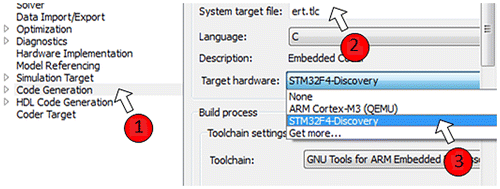
As shown in Figure , in order to create a PIL block for the MPPT Controller, the STM32F4 Discovery is selected as a target hardware.
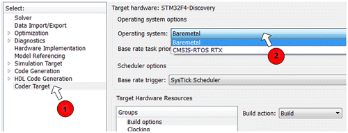
As shown in Figure , Baremetal or CMSIS-RTOS RTX can be used as an operating system (OS). Both OS will offer similar performance, however, each OS use different scheduling algorithm. For efficiency and full visibility of the scheduler code choose Baremetal, and prefer CMSIS-RTOS RTX to generate code compatible with legacy code.
As presented in Figure , the PIL block is generated and connected to the plant model so as to acquire the PV voltage and current, after that the PIL block will compute the duty cycle by using the modified algorithm and send it to the plant model through the ST-Link interface.
The result obtained using PIL test is presented in Figure . And it is compared with that of the MIL and SIL tests, and as shown the PIL result is in accordance with MIL and SIL results.
By using PIL test, both Simulink and STM32F4 board will run at the same time and will exchange data based on the modified MPPT algorithm implemented by the PIL block. Therefore, PIL test can be used as a low-cost solution to test the hardware implementation of MPPT algorithm under different conditions of irradiation and temperature.
3.4. Recapitulation
Note that, if the tests’ results (MIL/SIL/PIL) are different or they are not in accordance with the algorithm requirements, it means that somewhere in the process there is a problem. For example, if MIL behavior is not in accordance with the algorithm requirements, it means that there is a mismatch between Simulink model and algorithm. Therefore, it is required to correct the model according to the algorithm requirements. Thus, if SIL result is not in accordance with MIL result, that means that the software generated from the model for the host computer is not in accordance with the model. Therefore, it is required to correct the software according to the algorithm requirements. The same for PIL, if its result is not in accordance with MIL and SIL results, it means that the software generated from the model for the STM32F4 Board is not in accordance with the model. Therefore, it is required to correct the software according to the algorithm requirements. Anyway, according to DO-178C, the objective is to produce software which is compliant with its requirements (MPPT algorithm) (DO-178C, Citation2011).
On the other hand, the performances of the modified variable step INC algorithm are compared to the performances of different variable step INC algorithms proposed in some existing works in Table . As shown, our proposed presents the faster response and one of the highest efficiencies of more than 98%, thus the power ripples is almost neglected.
Table 3. Comparison between the proposed work and some existing works in the area of PV systems
4. Conclusion
Three manners of tests (MIL/SIL/PIL) mostly used for automotive and aeronautical embedded system are employed in this work, that in order to validate the functionality and robustness of the modified variable step INC algorithm. As a result, the responses of the three tests are in accordance with the MPPT algorithm requirements, which in turn this work contributes to achieve the objective of DO-178C norm. In addition, the results show that the modified algorithm avoids the steady-state oscillations and increases the tracking speed under sudden irradiance variation. In the light of that, the MPPT is tested on STM32F4 Discovery board; therefore the performance obtained will be the same by using a real PV panel. Subsequently, the PIL test can be used as a low-cost solution to test the hardware implementation of MPPT algorithm under different conditions of irradiation and temperature.
So by using these kinds of tests, we took advantage of safety level integrated in automotive and aeronautical embedded system, and note that by using this work, the MPPT system can be integrated in the aeronautical area.
Funding
The authors received no direct funding for this research.
| Nomenclatures | ||
| a | = | is the diode’s ideality factor |
| F | = | is switching frequency [Hz] |
| ID | = | is the diode current [A] |
| I | = | is the panel output current [A] |
| Is | = | is the panel reverse saturation current [A] |
| Iph | = | is the panel photocurrent [A] |
| Io | = | is the output current of the Boost converter [A] |
| K | = | is the constant of Boltzmann [J K−1] |
| Ns | = | is the number of cells connected in series |
| q | = | is the electron charge [C] |
| Rs | = | is the series resistance [Ω] |
| Rsh | = | is the shunt resistance [Ω] |
| R | = | is the load [Ω] |
| T | = | is the junction temperature [K] |
| VD | = | is the diode voltage [V] |
| V | = | is the panel output voltage [V] |
| Vo | = | is the output voltage of the Boost converter [V] |
| Greek letter | ||
| α | = | is the duty cycle |
| Abbreviations | ||
| CAN | = | Controller Area Network |
| INC | = | Incremental Conductance |
| MBD | = | Model-Based Design |
| MIL | = | Model In the Loop |
| MPP | = | Maximum Power Point |
| MPPT | = | Maximum Power Point Tracking |
| P & O | = | Perturb and observe |
| SIL | = | Software In the Loop |
| PIL | = | Processor In the Loop |
| PV | = | Photovoltaic |
| PWM | = | Pulse Width Modulation |
| STC | = | Standard Test Conditions |
| USB | = | Universal Serial Bus |
Additional information
Notes on contributors
Saad Motahhir
Saad Motahhir received the Technical University Degree in Electrical & Electronic Industry from the High School of Technology of Fez, Morocco, in June 2011, and he received Embedded System and Industrial Computer Engineering Diploma from the National School of Applied Science of Fez, Morocco in June 2014. He is a member of the Laboratory of Production Engineering, Energy, and Sustainable Development. His researches are based on solar energy and smart systems.
Abdelaziz El Ghzizal
Abdelaziz El Ghzizal is a member of the Laboratory of Production Engineering, Energy, and Sustainable Development. Research field: Multilevel inverters optimization of the power extracted from Photovoltaic Panels—Smart networks. Currently, he is a professor in Electrical Engineering in the High School of Technology of Fez.
Souad Sebti
Souad Sebti is a member of the Laboratory of Production Engineering, Energy, and Sustainable Development. Research field: Optimization of the power extracted from Photovoltaic Panels—Smart systems. Currently, she is a Professor in Electrical engineering at the High School of Technology of Fez.
Aziz Derouich
Aziz Derouich is a Professor at the Higher School of Technology, Sidi Mohamed Ben Abdellah University, Fez, Morocco. His research interests include electrotechnical systems, static converters, electrical machines control, renewable energy, and E-learning.
References
- Abusorrah, A., Al-Hindawi, M. M., Al-Turki, Y., Mandal, K., Giaouris, D., Banerjee, S., & Papadopoulou, S. (2013). Stability of a boost converter fed from photovoltaic source. Solar Energy, 98, 458–471.10.1016/j.solener.2013.09.001
- Ahmed, J., & Salam, Z. (2016). A Modified P&O maximum power point tracking method with reduced steady-state oscillation and improved tracking efficiency. IEEE Transactions on Sustainable Energy, 7, 1506–1515.10.1109/TSTE.2016.2568043
- Barker, L., Neber, M., & Lee, H. (2013). Design of a low-profile two-axis solar tracker. Solar Energy, 97, 569–576.10.1016/j.solener.2013.09.014
- Bringmann, E., & Krämer, A. (2008). Model-based testing of automotive systems. 1st International Conference In Software Testing, Verification, and Validation, (pp. 485–493). IEEE.
- Du, Y., & Lu, D. D. C. (2011). Battery-integrated boost converter utilizing distributed MPPT configuration for photovoltaic systems. Solar Energy, 85, 1992–2002.10.1016/j.solener.2011.05.008
- Dubois, H., Peraldi-Frati, M. A., & Lakhal, F. (2010). A model for requirements traceability in a heterogeneous model-based design process: Application to automotive embedded systems. 15th IEEE international conference in Engineering of complex computer systems, (pp. 233–242). IEEE.
- Eze, V. H. U., Iloanusi, O. N., Eze, M. C., & Osuagwu, C. C. (2017). Maximum power point tracking technique based on optimized adaptive differential conductance. Cogent Engineering, 1339336.
- Faraji, R., Rouholamini, A., Naji, H. R., Fadaeinedjad, R., & Chavoshian, M. R. (2014). FPGA-based real time incremental conductance maximum power point tracking controller for photovoltaic systems. IET Power Electronics, 7, 1294–1304.10.1049/iet-pel.2013.0603
- Fathabadi, H. (2016a). Novel high efficient offline sensorless dual-axis solar tracker for using in photovoltaic systems and solar concentrators. Renewable Energy, 95, 485–494.10.1016/j.renene.2016.04.063
- Fathabadi, H. (2016b). Novel high efficiency DC/DC boost converter for using in photovoltaic systems. Solar Energy, 125, 22–31.10.1016/j.solener.2015.11.047
- Glasner, I., & Appelbaum, J. (1996). Advantage of boost vs. buck topology for maximum power point tracker in photovoltaic systems. Nineteenth Convention of Electrical and Electronics Engineers, (pp. 355–358). IEEE.
- Hu, M., Zeng, G., Yao, H., & Tang, Y. (2010). Processor-in-the-loop demonstration of coordination control algorithms for distributed spacecraft. IEEE International Conference in Information and Automation (ICIA), (pp. 1008–1011). IEEE.
- Ishaque, K., & Salam, Z. (2011). An improved modeling method to determine the model parameters of photovoltaic (PV) modules using differential evolution (DE). Solar Energy, 85, 2349–2359.10.1016/j.solener.2011.06.025
- Kadri, R., Andrei, H., Gaubert, J. P., Ivanovici, T., Champenois, G., & Andrei, P. (2012). Modeling of the photovoltaic cell circuit parameters for optimum connection model and real-time emulator with partial shadow conditions. Energy, 42, 57–67.10.1016/j.energy.2011.10.018
- Kawamoto, H., & Shibata, T. (2015). Electrostatic cleaning system for removal of sand from solar panels. Journal of Electrostatics, 73, 65–70.10.1016/j.elstat.2014.10.011
- Loukriz, A., Haddadi, M., & Messalti, S. (2016). Simulation and experimental design of a new advanced variable step size Incremental Conductance MPPT algorithm for PV systems. ISA Transactions, 62, 30–38.10.1016/j.isatra.2015.08.006
- Mathworks. (2016a). Supported standards and products. Retrieved September 04, 2017 from https://www.mathworks.com/products/do-178/supported.html
- Mathworks. (2016b). PV array. Retrieved May 04, 2017 from https://fr.mathworks.com/help/physmod/sps/powersys/ref/pvarray.html
- Mohan, N., & Undeland, T. M. (2007). Power electronics: Converters, applications, and design. Hoboken: John Wiley & Sons.
- Motahhir, S., El Ghzizal, A., Sebti, S., & Derouich, A. (2015). Proposal and implementation of a novel perturb and observe algorithm using embedded software. In 3rd International Renewable and Sustainable Energy Conference (IRSEC), (pp. 1–5). IEEE.
- Motahhir, S., El Ghzizal, A., Sebti, S., & Derouich, A. (2016). Shading effect to energy withdrawn from the photovoltaic panel and implementation of DMPPT using C language. International Review of Automatic Control, 9, 88–94.10.15866/ireaco.v9i2.8850
- Motahhir, S., Chalh, A., El Ghzizal, A., Sebti, S., & Derouich, A. (2017). Modeling of photovoltaic panel by using proteus. Journal of Engineering Science and Technology Review, 10, 8–13.10.25103/jestr
- Moy, Y., Ledinot, E., Delseny, H., Wiels, V., & Monate, B. (2013). Testing or formal verification: DO-178C alternatives and industrial experience. IEEE Software, 30, 50–57.10.1109/MS.2013.43
- Nayak, B., Mohapatra, A., & Mohanty, K. B. (2017). Selection criteria of dc-dc converter and control variable for MPPT of PV system utilized in heating and cooking applications. Cogent Engineering, 4(1), 1363357.
- Poulek, V., Khudysh, A., & Libra, M. (2016). Self powered solar tracker for Low Concentration PV (LCPV) systems. Solar Energy, 127, 109–112.10.1016/j.solener.2015.12.054
- Radjai, T., Rahmani, L., Mekhilef, S., & Gaubert, J. P. (2014). Implementation of a modified incremental conductance MPPT algorithm with direct control based on a fuzzy duty cycle change estimator using dSPACE. Solar Energy, 110, 325–337.10.1016/j.solener.2014.09.014
- RTCA. (2011). DO-178C. Software considerations in airborne systems and equipment certification.
- Saharia, B. J., Manas, M., & Talukdar, B. K. (2016). Comparative evaluation of photovoltaic MPP trackers: A simulated approach. Cogent Engineering, 3(1), 1137206.
- Sanjaya, M. (2006). Switching power supplies A to Z. Newnes. Retrieved from https://www.sciencedirect.com/science/book/9780123865335
- Santos, J. L., Antunes, F., Chehab, A., & Cruz, C. (2006). A maximum power point tracker for PV systems using a high performance boost converter. Solar Energy, 80, 772–778.10.1016/j.solener.2005.06.014
- Sivakumar, P., Kader, A. A., Kaliavaradhan, Y., & Arutchelvi, M. (2015). Analysis and enhancement of PV efficiency with incremental conductance MPPT technique under non-linear loading conditions. Renewable Energy, 81, 543–550.10.1016/j.renene.2015.03.062
- Soon, T. K., & Mekhilef, S. (2015). A fast-converging MPPT technique for photovoltaic system under fast-varying solar irradiation and load resistance. IEEE Transactions on Industrial Informatics, 11, 176–186.10.1109/TII.2014.2378231
- Tey, K. S., & Mekhilef, S. (2014). Modified incremental conductance MPPT algorithm to mitigate inaccurate responses under fast-changing solar irradiation level. Solar Energy, 101, 333–342.10.1016/j.solener.2014.01.003
- Verma, D., Nema, S., Shandilya, A. M., & Dash, S. K. (2016). Maximum power point tracking (MPPT) techniques: Recapitulation in solar photovoltaic systems. Renewable and Sustainable Energy Reviews, 54, 1018–1034.10.1016/j.rser.2015.10.068
- Villalva, M. G., Gazoli, J. R., & Filho, E. (2009). Comprehensive approach to modeling and simulation of photovoltaic arrays. IEEE Transactions on Power Electronics, 24, 1198–1208.10.1109/TPEL.2009.2013862
- Visconti, P., Costantini, P., Orlando, C., Lay-Ekuakille, A., & Cavalera, G. (2015). Software solution implemented on hardware system to manage and drive multiple bi-axial solar trackers by PC in photovoltaic solar plants. Measurement, 76, 80–92.10.1016/j.measurement.2015.08.024
- Von Maurich, I., & Güneysu, T. (2014). Towards side-channel resistant implementations of QC-MDPC McEliece encryption on constrained devices. PQCrypto, 2014, 266–282.
- Wu, J., Zhang, B., & Wang, L. (2016). Optimum design and performance comparison of a redundantly actuated solar tracker and its nonredundant counterpart. Solar Energy, 127, 36–47.10.1016/j.solener.2016.01.017
- Zakzouk, N. E., Elsaharty, M. A., Abdelsalam, A. K., Helal, A. A., & Williams, B. W. (2016). Improved performance low-cost incremental conductance PV MPPT technique. IET Renewable Power Generation, 10, 561–574.10.1049/iet-rpg.2015.0203
- Zhou, Z., Holland, P. M., & Igic, P. (2014). MPPT algorithm test on a photovoltaic emulating system constructed by a DC power supply and an indoor solar panel. Energy Conversion and Management, 85, 460–469.10.1016/j.enconman.2014.06.007

