
 ?Mathematical formulae have been encoded as MathML and are displayed in this HTML version using MathJax in order to improve their display. Uncheck the box to turn MathJax off. This feature requires Javascript. Click on a formula to zoom.
Abstract
Flexible forming techniques, such as multi-point forming (MPF), are employed in manufacturing to reduce the time and cost of production. MPF uses a set of height-adjustable pins to construct free-form three-dimensional surfaces. Springback is a common phenomenon in forming including MPF which, if not properly catered for, will lead to parts that are out of specification. This paper introduces a detailed numerical approach for predicting springback in MPF. FE models were developed to simulate MPF of doubly curved panels in Aluminium alloy 5251-O. The Response Surface Method and the analysis of variance technique were employed to identify the most significant process parameters and to determine their optimal setting. The influence of these parameters on thickness variations across the formed panel and the subsequent effect of those variations on the amount of springback were investigated. It was found that the radius of curvature had the most significant effect on springback and thickness variation. Minimum springback can be achieved by introducing high strains through sheet stretching.
Public Interest Statement
Metal panels are using in industry applications such as automotive, railways, constructions, house applications, etc. The traditional metal forming tools are costly especially in low production and long adjustment time. Multipoint forming is a forming technique has been developed to replace the solid tools in some applications, which allows producing different part shapes by using same tools throughout adjusting the pins in height to get the desired shape. In sheet metal forming process a number of defects appear in final part, whether during or after the process, such as dimpling, wrinkling, rupture, springback, etc. as a result of an inefficient control of working parameters. Finite element analysis and optimization technique have been employed to produce a final part with acceptance quality, and minimize development time and cost. In this study, an investigation of some working parameters on the springback and thickness distribution has been carried out.
1. Introduction
Multi-point forming (MPF) is a flexible sheet forming technique. A MPF tool consists of two matrices of pins that can be individually varied in length to allow the approximation of a three-dimensional surface as shown in Figure . For whole MPF process in details see reference (Abosaf et al., Citation2017). The multi-point forming idea was first presented in 1969 by Nakajima (Citation1969) who created dies that could easily be modified to accommodate changes to the part design. A die consisting of three rows of pins was fabricated by Cai and Li (Citation2002) which was capable of forming metal plates into different shapes.
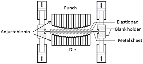
In MPF of a metallic sheet, the workpiece is exposed to a mixture of elastic-plastic bending and stretching. These deformation modes are usually accompanied by elastic recovery of the sheet, i.e. springback. There are many parameters that affect geometrical accuracy in the MPF process including pin dimensions, radius of curvature of the formed panel, blank clamping force and the properties of the pad between the pin matrix and the workpiece. There have been a number of investigations into MPF technology to control or compensate for springback and improve geometric accuracy.
Heo, Seo, Ku, Kim, and Kang (Citation2009) studied the effect of blank clamping force and punch dimensions on the deformed part. They concluded that the smaller the pin, the better the quality of the formed surface. Abosaf et al. (Citation2017) reported that the pin size and radius of the formed part have a significant impact on shape accuracy in MPF. Zareh-Desari, Davoodi, and Vedaei-Sabegh (Citation2015) demonstrated that the elastic cushion is an essential element in multipoint deep drawing (MPDD) and has a significant effect on the accuracy of the product. Sun, Li, Yan, and Zhong (Citation2007) found that using a flexible blank holder improved the forming limit and eliminated wrinkling in thin sheets.
A number of techniques have been developed to compensate for or decrease springback in MPF. Wenner (Citation1983) found that preloading the sheet could reduce springback at the end of the forming process. Over forming the sheet to compensate for springback in MPF was proposed by Li, Cai, and Li (Citation2000). For a given shape, Li, Seo, Heo, Kang, and Kim (Citation2010) showed that springback decreased with thick blanks.
Woellner, Lajarin, and Marcondes (Citation2013) investigated the effect of blank holder force and material properties on springback in deep drawing for which MPF tools can be used. It was reported that the yield strength of the workpiece had a significant effect on geometric accuracy. Materials with high yield strength such as steel will experience high springback. It was also concluded that clamping the workpiece was essential to reducing springback. Davoodi and Zareh-Desari (Citation2014) used a MPF tool to perform deep drawing. They concluded that adopting elastic pads with the minimum possible thickness and high hardness reduced springback. Additionally, using small pins had a similar effect on springback, which agrees with the results presented by Abosaf et al. (Citation2017). However, Davoodi and Zareh-Desari ignored the blank holder clamping force although it had a significant impact on springback as reported by Woellner et al. (Citation2013).
Finite element analysis is a cost-effective tool for understanding the influence of process parameters on springback and geometrical accuracy (Abosaf et al., Citation2017; Li et al., Citation2010; Wang, Cai, Li, & Lan, Citation2012; Zareh-Desari et al., Citation2015; Zareh-Desari, Davoodi, & Vedaei-Sabegh, Citation2017). Design of Experiments (DOE) and Analysis of Variance (ANOVA) are used in industry to explore the effects of process parameters (Essa, Citation2010; Read, Wang, Essa, & Attallah, Citation2015; Srinivasan, Vasudevan, & Padmanabhan, Citation2013). The literature reviewed indicates that pin size, part geometry, blank holder force and thickness and Young’s modulus of elastic cushion are the most important process parameters in MPF. Previous studies focused on geometrical accuracy and surface quality, in particular, dimpling and wrinkling. However, there have been few attempts to investigate the effect of the above parameters on springback.
In this work, Finite Element Analysis was used to simulate the MPF of doubly curved aluminium sheets. As an existing MPF tool (Abosaf et al., Citation2017) was to be employed to validate the simulation results, the pin size was a fixed parameter. The Response Surface Method was applied to study the influence of the other process parameters in MPF, i.e. part geometry (radius of curvature), blank holder force, elastic cushion thickness and modulus. Both the amounts of springback and thickness variation across the part were studied and the relationship between thickness distribution and springback was established.
The paper is organised as follows. Section 2 covers the numerical modelling of MPF and the mechanical properties of the blank material. The validation of the FE model is described in Section 3. Section 4 presents the design of experiments. Section 5 discusses the results of process optimisation. The prediction of process parameters is described in section 6. Section 7 compares modelling and experimental results. Section 8 focuses on thickness distribution in the formed part. Section 9 concludes the paper.
2. Numerical modelling of MPF
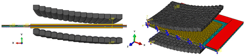
A finite element model was developed to study the MPF process. The model simulates two sets of pins forming the punch and the die respectively, the blank, two sheets of elastic cushion and the blank holder. Figure shows the components of the model. Due to symmetry, only a quarter of all components were modelled to save computation time.
Figure 2. Finite element model.
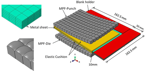
The model was developed to form doubly curved parts with different radii of curvature. 10 × 10 mm pins with 10 mm tip radius were used as recommended by Abosaf et al. (Citation2017). The active blank dimensions (under the pins) were 300 mm × 200 mm. The punch and die each contained 30 × 20 pins.
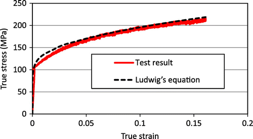
The blank material was aluminium alloy 5251-O of 1.2 mm thickness. To determine the mechanical properties of the material in the different directions, tensile tests were carried out using a Zwick/Roll test machine on specimens prepared at 0, 45, 90° with respect to the rolling direction . Table shows the material properties.
Table 1. Mechanical properties of Aluminium alloy 5251-O
An isotropic model was applied to describe the yield behaviour of the material. The elastic behaviour was defined by the modulus of elasticity and Poisson’s ratio. The plastic behaviour was modelled using Ludwig’s equation (Hosford & Caddell, Citation2011):(1)
(1)
where σ is true stress, σ0 the yield stress, K the hardening coefficient, ε true strain and n the hardening exponent. Figure shows the stress-strain curve for the tested material.
Figure 3. Stress-strain curves for aluminium alloy 5251-O.
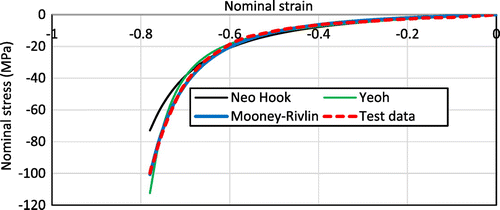
The non-linear hyperelastic behaviour of polyurethane with a Shore hardness of A 90 was modelled in this study (Abosaf et al., Citation2017; Heo, Seo, Noh, Ku, & Kang, Citation2010). Finite element analysis was used to identify the constitutive model to describe the behaviour of the elastic cushion. Three models, namely, Mooney- Rivlin, Yeoh and Neo Hook, were tested against experimental data as shown in Figure . It can be seen that the Mooney–Rivlin hyperelastic material model gave the best fit. Hence, it was selected to characterise the behaviour of the elastic cushion. In this constitutive model, the strain energy per unit volume can be calculated as (Sala, Citation2001):(2)
(2)
Figure 4. Hyperelasticity evaluations for A90 by ABAQUS.
where U is the strain energy per unit of reference volume, C10 and C01 are temperature- dependent material constants, The values of C10 and C01 are 0.861 and 0.354 respectively and ,
are the first and second invariants of the deviatoric strain tensor in the material (Zareh-Desari et al., Citation2017).
The dimensions of the blank were 213.5 × 162.5 × 1.2 mm thick and those of the elastic cushion were 153.5 × 102.5 × 3 mm thick. The blank and elastic cushion were modelled in ABAQUS using deformable solid elements of type C3D8R. Five layers of elements through the blank thickness were employed as recommended by Wang et al. (Citation2012). Similarly, for the cushion, three layers of elements were used. Thus, the number of elements in the models were 1,084,180 and 47,201 for the blank and the cushion respectively. (It is recalled that a quarter of the blank and cushion was modelled.) The pins were arranged to form a doubly curved surface (a saddle) with 400 mm radii of curvature. The punch and the die were modelled as discrete rigid bodies and the R3D4 element type was used as recommended by Zareh-Desari et al. (Citation2017). Finally, the blank holder was modelled as an analytical rigid body, as this was computationally less expensive than a discrete rigid part (Dassault Systems, Citation2013). Symmetrical boundary conditions were applied to the sheet and elastic cushion. The die and the lower part of the blank holder were fixed in the X, Y and Z directions while the punch and the upper part of the blank holder were fixed in the X and the Z directions only and free to move along the Y direction as shown in Figure . The Explicit Dynamic Solver in ABAQUS was used for the forming (Wang et al., Citation2012) stage while the unloading (springback) stage was solved with Standard ABAQUS.
Figure 5. Tools position, Mesh and boundary conditions in the FE model.
3. FE model validation
The finite element model was experimentally validated using the setup reported by Abosaf et al. (Citation2017). Figure shows the MPF setup for the case with 10 mm pins, 400 mm radius of curvature, 15 KN blank holder (Heo et al., Citation2010) force and 3 mm elastic cushion thickness. Tests were carried out to validate the computed results for the forming force and part profile. It can be seen that the predicted forming force was 60 KN while the experimental force was 63 KN and both demonstrated the same trend (Figure ).
Figure 6. Experimental setup used by Abosaf et al. (Citation2017).
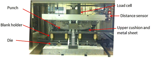
Figure 7. Model validation: Forming force.
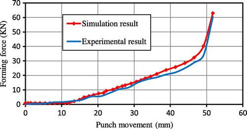
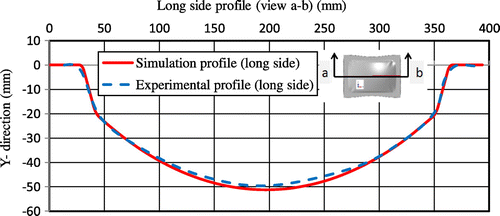
Figure shows the predicted profile of the formed sheet using the FE model and the experimentally measured profile using a FARO Edge Arm 3D scanner at path a-b. There was good agreement between the experimental and simulation results which differed by at most 1.94 mm near the centre of the sheet.
Figure 8. Model validation: Final profile.
4. Design of experiments (DOE)
Design of experiments and ANOVA have been reported to be useful in investigating the influence of process parameters in sheet metal forming (Abosaf et al., Citation2017; Essa, Citation2010). In this work, the most important process parameters, i.e. radius of curvature, thickness of elastic cushion and blank holder clamping force, were considered (Abosaf et al., Citation2017; Heo et al., Citation2009, Citation2010). Each parameter was varied over three levels (low, medium and high) as shown in Table . Using the Face Centred Response Surface Method, a set of 17 experiments was derived for the three working parameters as shown in Table .
Table 2. Level and value of the DOE parameters
Table 3. Experimental plan and simulation results
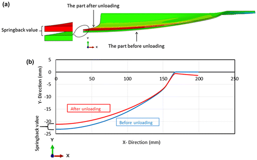
Springback and thickness uniformity were adopted to evaluate the quality of the formed part. Figure shows the sheet profile before and after unloading and how springback was evaluated. The sheet profile after unloading was obtained using 3D scanning (see Figure ). The displacement in the Y-direction after the unloading step computed with standard ABAQUS was used to represent springback in the formed part (Li et al., Citation2010). Additionally, the following equation was employed to calculate the thickness variation of deformed parts.(3)
(3)
Figure 9. (a) 3D diagram of deformed sheet, (b) sheet profile showing how spring back was evaluated.
In Equation (3), N represents the total number of points where thickness was measured, xi is the thickness value at point i and = mean value of thickness for all selected points.
5. DOE results and discussion
Table shows the 17 experimental conditions and corresponding measurements of springback and thickness variation. All the simulation results were statistically analysed using Design Expert 7.0 (Abosaf et al., Citation2017; Hassanin, Francesco, El-Sayed, Liu, & Essa, Citation2016; Păunoiu, Maier, Teodor, & Găvan, Citation2011). Analysis of Variance (ANOVA) was performed to identify significant process parameters. In this investigation, the null hypothesis was that the factor under consideration was insignificant. A significance level of 5% was used which means that the more the p-value falls below 0.05 the more important the factor (Abosaf et al., Citation2017). Table shows the p-values for the main factors and interactions. The ANOVA results indicate that springback is significantly affected by radius of curvature and blank holder force while thickness variation is significantly affected by radius of curvature, blank holder force as well as the interaction between blank holder force and elastic cushion thickness as shown in Table .
Table 4. Factors and corresponding p-values
5.1. Springback
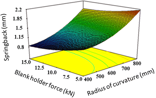
In MPF, geometrical errors can be divided into two kinds. The first kind occurs before unloading (dimpling and wrinkling) and the second after unloading (springback) (Păunoiu, Maier, Teodor, & Găvan, Citation2011). The curvature radius of the forming sheet after unclamped compared to the desired radius was chosen as the evaluation criterion. As indicated before and shown in Figure , radius of curvature and blank holder force have significant effects on springback. It can be seen that reducing the radius of curvature decreases springback. A similar observation was also reported by Li et al. (Citation2010). On the other hand, springback reduces when a high blank holder force is used. Very similar results were also presented by Woellner et al. (Citation2013). Apparently, a small radius of curvature or high blank holder force leads to high plastic deformation. When a small radius of curvature and/or a large blank holder force is adopted, a large of deformation occurs in the formed part. Thus, when the sheet is unclamped, the elastic recovery becomes small, leading to a reduction in springback (Li et al., Citation2000, Citation2010). Figure shows that the minimum springback can be achieved by using small radius and high blank holder force.
Figure 10. Effect of radius of curvature and blank holder force on springback.
5.2. Thickness variation
Figure shows the effect of radius of curvature and blank holder force on thickness variation. It can be noticed that increasing the radius of curvature has a substantial effect on reducing thickness variation which means better thickness uniformity in the formed part. When a large radius of curvature is used (800 mm), the workpiece profile is contacted by more pins at the beginning of the deformation process which leads to stress uniformity and reduces thickness variation. Similar observations were also reported by previous investigations (Abosaf et al., Citation2017; Lee, Kim, Kim, Wenner, & Chung, Citation2005). When a high blank holder force is used, large stretching deformation takes place across the workpiece causing high thickness variation (Woellner et al., Citation2013). Therefore, minimum thickness variation can be obtained by using a large radius of curvature and a low blank holder force.
Figure 11. Effect of radius of curvature and blank holder force on sheet thickness variation.
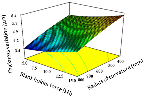
Figure shows the effect of interaction between elastic cushion thickness and blank holder force on thickness variation. It can be seen that when a thick (7 mm) elastic cushion is used, the effects of blank holder force on thickness variation become insignificant. On the other hand, with a thin (3 mm) elastic cushion, the effects of blank holder force on thickness variation are considerable.
Figure 12. Effect of interaction between blank holding force and elastic cushion thickness on thickness variation.
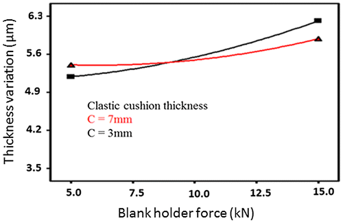
When a thick elastic cushion is employed, the local deformation is minimal and stress distribution on the sheet surface becomes uniform. Also, the blank holder force is better distributed across the workpiece. However, when a thin elastic cushion is used, local deformation by individual pins becomes noticeable, which leads to a non-uniform distribution of stresses. In this case, any small change in the blank holder force will affect local sheet thinning and thus thickness variation (Wang et al., Citation2012).
6. Prediction of response factors
An empirical model was developed to predict springback and thickness variation using a general second-order polynomial equation (Equation (4)). The equation was constructed based on the process parameters (radius of curvature, elastic cushion thickness and blank holder force). Table lists the coefficient x1–x9 for the different process parameters.(4)
(4)
Table 5. Coefficient values of objective function
where X is a constant for the given response factor, A is the radius of curvature, B is the blank holder force and C is the thickness of elastic cushion and x1–x9 are the model coefficients listed in Table . Equation (4) allows the prediction of springback and thickness variation under any combination of process constraints.
7. Optimisation of process parameters
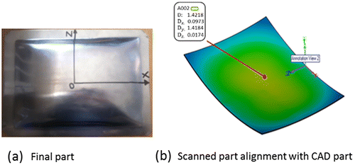
Equation (4) was used to find the optimum setting of process parameters. The aim was to minimise springback and thickness variation in the final part. The best setting of process parameters to achieve that objective was numerically obtained by solving Equation (4) using a generic algorithm to minimise springback and thickness variation. For a MPF die with 10 mm pins and with all process variables constrained within their preselected levels (see Table ), the optimal setting was: 600 mm radius of forming curvature, 8 KN blank holder force and 3 mm elastic cushion, as shown in Table . For experimental validation, a FARO Edge Arm 3D scanner with Geomagic control (http://www.faro.com/en-us/products/metrology/measuring-arm-faro-scanarm/applications#main, accessed on 19/02/2017) was used to capture a 3D point cloud image of the deformed part. This was then compared to the desired part surface and the deviation in the Y direction was taken to represent the amount of springback as shown in Figure . The thickness was measured using a digital micrometre with 0.01 mm resolution at a number of points across the centre of the formed part along the x-direction as shown in Figure . The mean and standard deviation were calculated and the standard deviation was used to represent the thickness variation as shown in Equation (3) previously. The experimental results for springback and thickness variation are shown in Table . It can be seen that very good agreement with the model results has been achieved.
Table 6. Numerical result against experimental validation
Figure 13. (a) Double curved deformed sheet, (b) 3D scanning results of deformed sheet for springback measurement.
8. Thickness distribution in the formed part
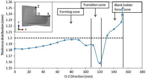
Springback is very sensitive to a number of factors that affect local deformation, including strain distribution and type of contact. Stretching and thinning are the preferred mode of deformation to reduce springback in the cold metal forming (Lee et al., Citation2005). Thickness distribution was investigated numerically for two cases, one when springback was high and the other when springback was low.
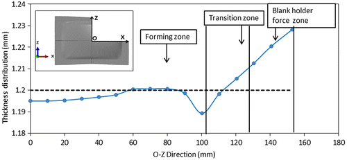
Figures and show the thickness distribution along two paths, O-X (the long side) and O-Z (the short side), for experiment 17 (see Table ). The predicted springback was 2.2 mm which was the worst case among all simulated conditions. For the long side O-X, it can be seen that thinning occurred across the sheet. Maximum thinning was observed at the sheet centre, which was the first point to contact the pins (Abosaf et al., Citation2017), and in the transition zone between the blank holder and the beginning of the forming area as shown in Figure . The sheet in this zone was exposed to high stretching due to clamping by blank holder while the punch pressed the sheet forward towards the die. However, for the short side O-Z as shown in Figure , sheet thinning appears at the beginning of the forming area as it is the first contact point between the punch and the sheet. As a result, localised stresses are generated to cause thinning in the middle of the part (Heo et al., Citation2009). However, sheet thickening took place around the beginning of the forming area. The thickening is due to compressive stress in the direction perpendicular to the drawn-in direction (Lee et al., Citation2005). Additionally, the flow of material from the centre to the edges under pressure from the punch (Liu, Li, & Ju, Citation2017) was suppressed by the blank holder. Also, the side of the sheet was not long enough and the height of the part (800 mm) was insufficient to accommodate the material flow from the centre. As a result, thickening happened. The maximum sheet thickening under the blank holder area in two cases along both paths is due to material accumulation as a result of the holding force which prevents the metal flow by different degrees depending on the value of the force.
Figure 14. Predicted thickness distribution along O-X (Experiment 17).
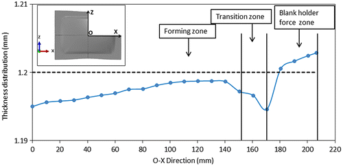
Figure 15. Predicted thickness distribution along O-Z (Experiment 17).
Figures and show the thickness distribution along the O-X and O-Z directions for experiment 2 (see Table ). The predicted springback for the experiment was 0.8 mm which was the best case among all simulated conditions. Here, the radius of curvature was 400 mm and the blank force was 15 KN. Thus, the depth of deformation was higher than in experiment 17 with a radius of curvature of 800 mm. This led to more stretching and a longer deformation path. As such, there was also more sheet thinning than in experiment 17. Also, the thinning was fully accommodated along the O-X and O-Z directions and no sheet thickening occurred in the forming area except the sheet under the blank holder. The large amount of deformation in the case of small radius of forming curvature (Li et al., Citation2000) combined with high sheet clamping force (Li et al., Citation2010) leads to low springback in the final part.
Figure 16. Predicted thickness distribution along O-X (Experiment 2).
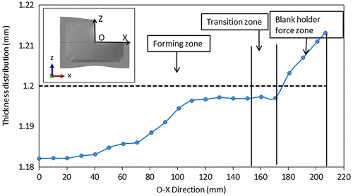
Figure 17. Predicted thickness distribution along O-Z (Experiment 2).
9. Conclusions
In this investigation, MPF of doubly curved aluminium 5151-O sheets was numerically simulated using finite element analysis. The Response Surface and Analysis of Variance methods were used to identify the parameters significantly affecting springback and thickness variation. The following conclusions can be drawn from this study:
| (1) | Springback is significantly affected by the radii of curvature of the part and blank holder force while thickness variation is significantly affected by radii of the curvature, blank holder force and the interaction between blank holder force and elastic cushion thickness. | ||||
| (2) | As the radii of curvature increase, springback increases and thickness variation decreases which is opposite to the effect of the blank holder force. | ||||
| (3) | The optimum condition to achieve minimum springback and thickness variation in this study was found to be 600 mm for the radius of forming curvature, 8kN for blank holder force and 3 mm for elastic cushion thickness, with all working parameters constrained within their preselected values. | ||||
| (4) | Having a large plastic deformation through sheet stretching and thinning while avoiding sheet thickening is the key factor in minimising springback. This can be achieved by using small radii of forming curvature and high blank holder forces. | ||||
Further work will be conducted on effective ways to minimise springback through using information on local resistance to forming. In this regard, an instrumented MPF tool is being constructed in which the force on and displacement of selected pins are measured to provide the feedback required for springback compensation.
Funding
This work was supported by the Engineering and Physical Sciences Research Council [grant number EP/L505225/1].
Acknowledgments
This work was part of the “Automated Manufacturing Process Integrated with Intelligent Tooling Systems (AUTOMAN)” project supported by the Engineering and Physical Sciences.
Research Council and Innovate UK (Grant Reference EP/L505225/1).
Additional information
Notes on contributors
Ali Elghawail
Ali Elghawail is a PhD candidate in manufacturing engineering at University of Birmingham; he has received his master degree in mechanical and material engineering at National University of Malaysia in 2009. Also, he is one of the staff in Industrial Engineering Department at College of Industrial Technology–Misurata–Libya. His research interests include production processes such as metal forming and metal machining. The current work is a part of his PhD research in reconfigurable panel of low press forms and the project was led by UPM Ltd, with consortium members including the University of Birmingham, Loadpoint Ltd, MG Motor UK Ltd, the Manufacturing Technology Centre, the University of Strathclyde, and Whiston Industries Ltd.
Related Research Data
References
- Abosaf, M. E., Essa, K., Alghawail, K., Tolipov, A., Su, S., & Pham, D. (2017). Optimisation of multi-point forming process parameters. The International Journal of Advanced Manufacturing Technology, 1–11.
- Cai, Z.-Y., & Li, M.-Z. (2002). Multi-point forming of three-dimensional sheet metal and the control of the forming process. International Journal of Pressure Vessels and Piping, 79(4), 289–296.10.1016/S0308-0161(02)00017-0
- Dassault Systems. (2013). Abaqus/CAE User’s Manual.
- Davoodi, B., & Zareh-Desari, B. (2014). Assessment of forming parameters influencing spring-back in multi-point forming process: A comprehensive experimental and numerical study. Materials & Design, 59, 103–114.10.1016/j.matdes.2014.02.043
- Essa, K. H. (2010). Optimization of conventional spinning process parameters by means of numerical simulation and statistical analysis. Proceedings of the Institution of Mechanical Engineers, Part B: Journal of Engineering Manufacture, 224(11), 1691–1705.10.1243/09544054JEM1786
- Hassanin, H., Francesco, M., El-Sayed, M. A., Liu, J., & Essa, K. (2016). Manufacturing of Ti–6Al–4 V micro-implantable parts using hybrid selective laser melting and micro-electrical discharge machining. Advanced Engineering Materials, 18(9), 1544–1549.10.1002/adem.v18.9
- Heo, S. C., Seo, Y. H., Noh, H. G., Ku, T. W., & Kang, B. S. (2010). Numerical study on effect of using elastic pads in flexible forming process. Transactions of the Korean Society of Mechanical Engineers A, 34(5), 549–556.10.3795/KSME-A.2010.34.5.549
- Heo, S. S., Seo, Y. H., Ku, T. W., Kim, J., & Kang, B. S. (2009). Study on application of flexible die to sheet metal forming process. Transactions of Materials Processing, 18(7), 556–564.
- Hosford, W. F., & Caddell, R. M. (2011). Metal forming: Mechanics and metallurgy. Cambridge: Cambridge University Press.10.1017/CBO9780511976940
- Lee, M.-G., Kim, D., Kim, C., Wenner, M. L., & Chung, K. (2005). Spring-back evaluation of automotive sheets based on isotropic–kinematic hardening laws and non-quadratic anisotropic yield functions, part III: Applications. International Journal of Plasticity, 21(5), 915–953.10.1016/j.ijplas.2004.05.014
- Li, L. S., Seo, Y. H., Heo, S. C., Kang, B. S., & Kim, J. (2010). Numerical simulations on reducing the unloading springback with multi-step multi-point forming technology. The International Journal of Advanced Manufacturing Technology, 48(1–4), 45–61.10.1007/s00170-009-2290-6
- Li, M. Y. J., Cai, Z., & Li, S. (2000). The research on multi-point alternate forming of sheet metal to minimize springback. Suxing Gongcheng Xuebao [Journal of Plasticity Engineering(China)], 7, 22–25.
- Liu, Y., Li, M., & Ju, F. (2017). Research on the process of flexible blank holder in multi-point forming for spherical surface parts. The International Journal of Advanced Manufacturing Technology, 89, 2315–2322.
- Nakajima, N. (1969). A newly developed technique to fabricate complicated dies and electrodes with wires. Bulletin of JSME, 12(54), 1546–1554.10.1299/jsme1958.12.1546
- Păunoiu, V., Maier, C., Teodor, V., & Găvan, E. (2011). Numerical analysis of multipoint forming process. International Journal of Modern Manufacturing Technologies, 3(2), 85–90.
- Read, N. W., Wang, W., Essa, K., & Attallah, M. M. (2015). Selective laser melting of AlSi10 Mg alloy: Process optimisation and mechanical properties development. Materials & Design (1980–2015), 65, 417–424.10.1016/j.matdes.2014.09.044
- Sala, G. (2001). A numerical and experimental approach to optimise sheet stamping technologies: Part II—Aluminium alloys rubber-forming. Materials & Design, 22(4), 299–315.10.1016/S0261-3069(00)00088-1
- Srinivasan, R., Vasudevan, D., & Padmanabhan, P. (2013). Application of response surface methodology for predicting springback in air bending of electro galvanised steel sheets. International Journal of Materials Engineering Innovation, 4(1), 35–56.10.1504/IJMATEI.2013.052809
- Sun, G. L., Li, M. Z., Yan, X. P., & Zhong, P. P. (2007). Study of blank-holder technology on multi-point forming of thin sheet metal. Journal of Materials Processing Technology, 187, 517–520.10.1016/j.jmatprotec.2006.11.133
- Wang, S. C., Cai, Z., Li, M., & Lan, Y. C (2012). Numerical simulation on the local stress and local deformation in multi-point stretch forming process. The International Journal of Advanced Manufacturing Technology, 60(9–12), 901–911.10.1007/s00170-011-3663-1
- Wenner, M. (1983). On work hardening and springback in plane strain draw forming. Journal of Applied Metalworking, 2(4), 277–287.10.1007/BF02833912
- Woellner, N., Lajarin, S. F., & Marcondes, P. V. P. (2013). Blank holder force influence on the springback of advanced high strength steels. In International Congress of Mechanical Engineering, Ribeirão Preto, SP, Brazil.
- Zareh-Desari, B. D., Davoodi, B., & Vedaei-Sabegh, A. (2015). Investigation of deep drawing concept of multi-point forming process in terms of prevalent defects. International Journal of Material Forming, 10, 193–203.
- Zareh-Desari, B., Davoodi, B., & Vedaei-Sabegh, A. (2017). Investigation of deep drawing concept of multi-point forming process in terms of prevalent defects. International Journal of Material Forming, 10(2), 193–203.