Abstract
The goal of this study was to determine the preferred handle design for two degrees of freedom steerable arthroscopic cutter by performing a two-step development approach. The expected usefulness and usability of control components of three entirely different handles were defined by an on-line survey with 101 students and the actual control by a standardised laboratory study with mock-up models by 16 students. The preferred handle design was integrated in a full functional prototype and optimized by 10 experts performing a meniscectomy on human cadaver knees. Students (survey 70% and task 91%) expected the same control behaviour as the experts (60%): steering a wheel to the right should evoke tip steering to the right regardless the orientation of the beak and moving a ring lever towards the handle’s centre point should evoke closure of the tip. Development of surgical instruments can benefit from expected control behavior based on daily life tools, but requires expert involvement for specific surgical tasks and context.
Public interest statement
To treat a so-called football knee (a cartilage tear in your knee), surgeons perform key-hole surgery. In one hand they hold the camera and in the other they use a cutting instrument. In this study, we investigate the preferred control of a new cutting instrument that allows steering of the instrument tip for precise cutting. Three entirely different handles and means of control were tested for cutting and steering with a single hand. Thereto, an on-line survey filled out by 101 students and actual instrument handling was performed by 16 with mock-up models. Their preferred handle design was integrated in a full functional prototype and optimized by 10 experts performing a football knee treatment on human cadaver knees. Students expected the same instrument control as the experts. Development of surgical instruments can benefit from expected control of daily life tools, but requires expert involvement to tune for surgical tasks.
1. Introduction
Gaining minimally invasive access to the pathology site in a confined cavity such as the knee joint can be challenging with rigid surgical instruments. On top of that, the tissues located in these particular body cavities (cartilage, ligaments) require substantial loads to machine (cut, punch, drill) (Tuijthof, Frühwirt, & Kment, Citation2013). As a result, a number of problems exists: the decreased reachability and interchange of instruments causes disruption of the work flow (Tuijthof, van Dijk, Herder, & Pistecky, Citation2005); healthy tissues surrounding the access portals can accidentally be damaged; due to interchange of instrument more bacteria can be introduced (Tuijthof et al., Citation2003). To solve these problems, a sideways steerable arthroscopic cutter has been developed (Horeman, Aguirre, Kerkhoffs, Dankelman, & Tuijthof, Citation2015; Horeman, Schilder, Aguirre, Kerkhoffs, & Tuijthof, Citation2015; Nai, Herder, & Tuijthof, Citation2011). This enables the surgeon to reorient the instrument tip if desired inside the joint cavity. A challenge is to determine how the user (the surgeon in this case) can operate this new instrument single-handedly, since there is an additional degree of freedom required for steering the tip (van Veelen, Meijer, Goossens, & Snijders, Citation2001). The goal was to determine the preferred handle design for the steerable arthroscopic cutter by performing a two-step handle development approach with a focus on subjective usability aspects.
2. Materials and methods
First a student test panel was used to evaluate individual ergonomic aspects of three handle designs to select a design based on subjective preference of the majority. Second, a panel of experts was asked to optimize the selected handle when using it in a real-life setting.
2.1. Guidelines and requirements for handle design
Based on ergonomic guidelines, existing hand-operated multi-degree of freedom instruments and the meniscectomy procedure, requirements were formulated for any handle design of the steerable arthroscopic cutter (Gibson, Citation1979; Goossens & van Veelen, Citation2001; Hedge, Citation1998; Matern, Citation2001; Patkin, Citation2001; van Veelen, Goossens, et al., Citation2001; van Veelen, Meijer, et al., Citation2001). The first set consisted of requirements on functionality and dimensional restrictions, which could be directly implemented without user evaluation:
| (1) | Two independent control components; one for opening and closing the tip, and one for side-ways tip steering (Tuijthof et al., Citation2003). | ||||
| (2) | The movement of fingers, hand and wrist should remain within allowable ranges, which implies the angle between the shaft and the handle to be between 14 and 50° (Hedge, Citation1998; Matern, Citation2001; Tilley, Citation2002; Van Veelen, Goossens, et al., Citation2001). | ||||
| (3) | If present, a grip opening should not exceed 80 mm (Van Veelen, Goossens, et al., Citation2001), a ring opening should be at least Ø 30 mm (Tilley, Citation2002), a grip circumference should be at least 130 mm (Tilley, Citation2002; Van Veelen, Goossens, et al., Citation2001), levers should have a contact area of at least 120 mm2 (Tuijthof et al., Citation2003; Wagner, Birt, Snyder, & Duncanson, Citation1996). | ||||
The second set consisted targeted usability, which required subjective user interpretation and was the focus of this study:
| (4) | Single-handed control by both hands requiring a symmetric design (Matern, Citation2001; Van Veelen, Goossens, et al., Citation2001). | ||||
| (5) | Control components should be actuated by fingers and/or the thumb (Matern, Citation2001; Tilley, Citation2002). | ||||
| (6) | Offer intuitive control by self-explaining elements that act as external memory on the status of the instrument tip (Voorhorst, Citation1998). | ||||
| (7) | Professional and trustworthy appearance in accordance with the users and working environment (Tuijthof et al., Citation2012). | ||||
| (8) | Stable grip when operating with latex gloves (Matern, Citation2001; Patkin, Citation2001). | ||||
| (9) | Maximum instrument mass is similar as current arthroscopic cutters (40 gram), else the handle’s mass distribution should be centred in the palm of the hand (Daams, Citation1994). | ||||
2.2. Handle designs
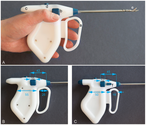
Three different handle designs were developed with dimensions based on several sources for handle design (Hedge, Citation1998; Matern, Citation2001; Tilley, Citation2002; Van Veelen, Goossens, et al., Citation2001). The first concept was inspired by laparoscopic instruments that have a handle for cutting and a wheel to rotate the tip around the shaft (Handle 1) (Sancibrian et al., Citation2014). The second concept was adapted from our previous work consisting of a single thumb lever to control sideways steering and cutting (Handle 2) (Tuijthof et al., Citation2003). The third concept was inspired by bone marrow biopsy needles that have a stable symmetric grip added with a turning wheel for sideways steering and two rings that move along the shaft for cutting (Handle 3). The three handles were designed in Solid Works (SolidWorks 2014 student edition, Design Solutions B.V., Bruchem, the Netherlands) and mock-up models were fabricated with rapid prototyping (polylactic acid in white and blue) (Figure ). Using the results of Step 1 and taking into account fabrication issues, a full functional prototype was constructed in which tip steering was enabled with a patented mechanism (Horeman, Aguirre, et al., Citation2015; Horeman, Schilder, et al., Citation2015) (Figure (A)). The prototype weighed 257 grams and was fabricated of medical grade materials with surgical steel (X5CrNiCuNb16.4) for the hinge components, stainless steel (ST 316) for the metal tubes and components in the handle; and white polyphenylene sulfone and blue polyetheretherketone for the plastic components.
Figure 1. Up: Drawings of the three different handles with in dark blue the controls for activation of the cutting and sideways steering. The letters indicate the direction of movement for each control and the numbers indicate the optional directions of movement of the instrument tip. These images were used in the survey of Step 1. Below: Mock-ups of the same handles to execute physical tests with the student panel.
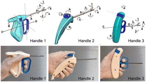
Figure 2. Full prototype of the steerable arthroscopic cutter. (A) The full prototype as used to perform the cadaver test executed by the experts. (a): pull and push lever. In current state the lever is in extreme push position corresponding with a fully opened instrument beak (e). (b): turning wheel to steer sideways. (c): extra handle shape to support stable grip when opening the instrument beak. (d): release button to disassemble the prototype. (B) dimensions of the full prototype (A) indicated in mm. (C) Optimized prototype with the changed dimensions indicated and the button to fixate the beak in neutral position (f).
2.3. Step 1 evaluation with a general user group in a laboratory setting
Our strategy was to evaluate the individual control components of the handles independently to identify users’ preference with tools from daily life as reference. Thereto, a minimum number of 97 participants need to be surveyed as was determined by a conservative power analysis with a standard deviation of 50%, an allowable difference of 10% and an alpha of 0.05. The survey was filled out by 101 students who were predominantly male (78), right handed (87), ages between 18 and 23 (83) and a technical background (77). The survey consisted of 44 questions covering Requirements 4–7 (Figures and ). Also, a physical test was performed by 16 students, who were male and had a technical background; while being predominantly right handed (14) and aged 18–23 (14).
Figure 3. Detailed results per handle targeting the self-explaining capacity and actual handling of the control elements per handle. Per control element (indicated in Figure ), the results of the survey indicate (A) the expected finger or wrist motion for operation, and (B) the expected movement of the instrument beak when handling. (C) Per control element, the counted control actions as performed during the mock-up test are given.
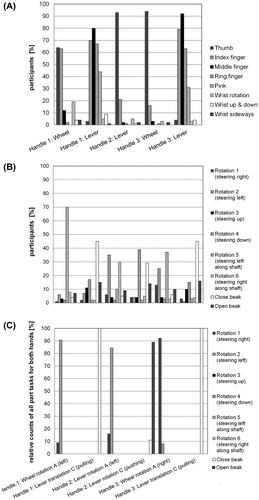
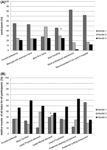
Figure 4. (A) Results of the survey questions that specifically targeted the selection of one preferred handle based on the drawings in Figure . (B) Results of the survey questions that specifically targeted the selection of one preferred handle based on the four tasks performed with the mock-up handles of Figure . The relative counts in the y-axis is composed as follows. For each task, the 6 items had to be filled out indicating the preferred handle for that item. Subsequently these were summed and divided by the total number of counts presented as a percentage.
The physical test with the mock-up handles consisted of three parts covering Requirements 4–8 (Figures and ). To minimize order bias, each subject was assigned to a different order of the handles. First, subjects were shown the first handle with the shaft end inserted in a hole of a custom-made test block to prevent the instrument tip from being exposed. Without touching or holding the handle, they were asked to (a) indicate the control components and (b) to indicate the expected control result when handling the component. Second, subjects were asked to manipulate the control components, again with the handle’s shaft end hidden in one of four holes in the test block. This forced the instrument in a certain spatial orientation and mimicked an access portal to the joint. In each orientation, one of four tasks was performed:
Task 1. Insert the instrument in the first hole and navigate the instrument tip to the right.
Task 2. Insert the instrument in the second hole, navigate the instrument tip to the right, cut an imagined piece of tissue and bring it outside the joint cavity.
Task 3. Insert the instrument upside down in the third hole and navigate the instrument tip to the left.
Task 4. Insert the instrument in the fourth hole, cut an imagined piece of tissue, navigate the instrument tip to the left, release the tissue and bring the instrument tip to the neutral position.
The task time and control actions for each of the tasks were documented with video-recordings. Subsequently, subjects were asked to fill out the NASA Task Load Index (TLX) (Hart, Citation1988) to document the workload per task. Third, subjects were asked to fill out their preference in a relative comparison of the three handles (Figure ).
2.4. Step 2 evaluation with an expert user group in a real-life setting
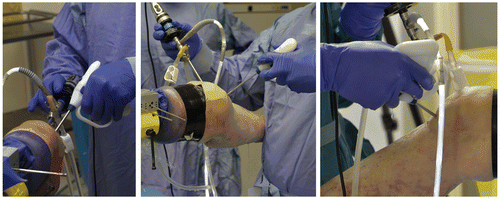
With the full prototype, a user evaluation was performed using fresh human cadaveric knees with a team of ten experts, who were predominantly male (9) and right handed (8). The orthopaedic surgeons performed at least 100 knee arthroscopies a year. First, the prototype was shown and an expert was asked, without touching or holding, to answer questions regarding the both control components. Second, the experts were assigned in couples to perform either a lateral or a medical meniscectomy on one human cadaver knee within a set time frame of 30 min (Figure ). The first expert to start made the access portals. The experts were instructed to perform a high quality meniscectomy, which was recorded by a video camera and the arthroscopic camera. Third, the experts were asked to fill out the NASA TLX (Hart, Citation1988) and questions regarding the weight distribution, fit in hand, ease of operation, appearance and room for improvement.
Figure 5. Impression of the cadaver tests. Handle 1 as implemented in the full prototype is held with different grips including upside down (right picture).
Based on the user feedback, the handle prototype was modified as follows: its grip size was reduced, the instrument lever was given a spring to keep the cutter open when not actuated, the cutting ring lever was made thinner and an additional slider was added to fixate the tip in the neutral position to access the portal (Figure (B)). In a second round, the experts were asked to hold and feel the optimized prototype and asked to fill out to the post-test survey a second time.
2.5. Statistical analysis
Per multiple choice question, the number of participants per choice option were counted, and converted to a percentage. A difference of 20% between answers given to the surveys in a relative comparison was considered relevant. Per motion of the tip as prescribed by the four tasks, the prevalence of control actions was counted. These counts were transferred into relative counts by division of the total count number. For comparison, the relative counts were uniformly with survey questions for comparison (Figure ). Questions of the expert survey were answered on a 10-point numerical rating scale (NRS). A 10-point NRS was chosen as all participants were Dutch and this grading system is used in all educational institutions. A value of 7 or greater was considered sufficient (Tuijthof, Visser, Sierevelt, Van Dijk, & Kerkhoffs, Citation2011). The presence of normal distributions of the datasets was assessed with Kologomorov-Smirnov tests. The task times, NASA TLX (range 0–100) and NRS were summarized with an average number and standard deviation. One-way analysis of variance tests (ANOVA tests) with Posthoc Bonferroni-tests were performed to determine significant differences between de experienced workload (NASA TLX) and task times. Finally, a paired t-test was performed to determine significant improvement on handle fit and control after optimizing the full prototype (NRS). The alpha significance level of 0.05 was corrected for multiple testing with the Bonferroni correction to 0.008 for NASA TLX and 0.025 for full prototype improvement assessment.
3. Results
3.1. Step 1 evaluation with a general user group in a laboratory setting
Over two-third of the student participants indicated that all handles were to be used by both hands (Handle 1: 65 out of 101, Handle 2: 72 out of 101, Handle 3: 69 out of 101). Figures and give a summary of the expected control of the handles based on pure visuals and the actual handling with the mock up models. For Handle 1, the turning wheel is expected to be used by the thumb or the index finger (>67%) and the lever by a combination of the index, middle and ring finger (>65%) (Figure (A)). When turning the wheel to left (direction A) (Figure ), 70% expects a rotation of the tip along the shaft to the left (Rotation 5) (Figure (B)); and in 91% of the actions the wheel was rotated to the left to move the tip to the left (Figure (C)). For Handle 2, the lever is expected to be used by the thumb (93%) (Figure (A)). When turning the lever to the left (direction A) (Figure ), 35% expect a rotation of the tip to the left (Rotation 2), 30% expect a rotation of the tip along the shaft to the right (Rotation 6) (Figure (B)); and in 84% of the actions the lever was rotated to the left to move the tip to the left (Figure (C)). For Handle 3, the turning wheel is expected to be used by the thumb (94%) and the lever by a combination of the index, middle and ring finger (>63%) (Figure (A)). When turning the wheel to the right (direction A) (Figure ), 37% expect a rotation of the tip along the shaft to the left (Rotation 5), 25% expect a rotation of the tip to the left (Rotation 2) (Figure (B)); and in 92% of the actions the wheel was rotated to the right to move the tip to the right (Figure (C)).
All tasks were performed within 22 s with the dominant and non-dominant with an average workload ranging between 28 and 58% (standard deviation ranged 16–28%) and showed no significant differences. In general, surveyed students preferred Handle 1, as it is expected to give the best grip, and offers the most professional appearance (Figure (A)). Handle 2 was indicated to give the best fit. No consensus was found for best handling. Students participating in the mock-up test preferred Handle 3, because this handle provides the most comfort, least frustration and preferred steering component (thumb wheel) (Figure (B)). The lever of Handle 1 was preferred for cutting. No consensus was found for the handle requiring the least physical and mental demand.
The results of Step 1 were inconsistent for some requirements. When analysing the individual control components, overall the combination of a wheel component to steer left and right; and a lever to open en close the beak was preferred (Figure ). This rejected Handle 2. Turning the wheel to the left should evoke turning the beak to the left, and pulling the lever should evoke beak closing (Figure ). This preferred handle control was implemented in the full prototype. Eventually, we decided to continue with the layout of Handle 1, because its cutting component (which is the main functionality) was preferred, this handle was more in line with conventional cutters and easier to connect with the tip; and the survey population was substantially large (Figure (A)).
3.2. Step 2 evaluation with an expert user group in a real-life setting
By solely visual inspection, seven experts indicated that the prototype was to be used by both hands. When turning the wheel to the left (direction A) (Figure ), six experts expect a rotation of the tip along the shaft to the left (Rotation 5) and two expect a rotation of the tip to the left (Rotation 2).
All experts were able to perform steering and cutting meniscus actions in a human cadaver knee (Figure ). In 4 out of 5 cadavers soft tissue was obstructing the sight and in 2 out of 5 the joints space was tight, which made it difficult to complete the full meniscectomy in the set time frame. This was confirmed by the experienced effort to perform the task (mean of average 64%) and the experienced performance (mean of 50%) (Figure (A)). Other than that, the experts felt not frustrated frustration and indicated rather low demands.
Figure 6. (A) Results of the experienced workload by the experts when performing a meniscectomy with the full prototype in a cadaver knee. (B) Results of the post-test survey where each of the items was scored on the NRS-scale. The same survey was filled out after adjustments made to the prototype.
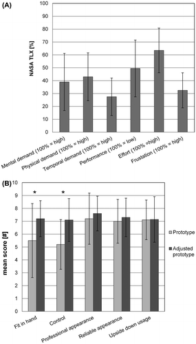
The post-test survey gives a mean value of 7 on all items after the recommended adjustments (Figure (B)). Eight experts indicate that the weight of the handle and the weight distribution of the prototype was adequate. This confirms sufficient acceptance and fulfilment of Requirements 4–9.
4. Discussion
The goal to identify a preferred handle design was achieved, because the final handle meets the set requirements (Hedge, Citation1998; Sperling, Dahlman, Wikström, Kilbom, & Kadefors, Citation1993). The two-step development approach appeared to be efficient to determine the expected behaviour of the instrument beak in relation to the preferred control components. With efficient, we imply that the laboratory setup and recruitment of larger groups of students are organized relatively quickly leading to meaningful results of subjective preference. This was confirmed, because the experts expected the same control behaviour as the students (Figures and ). This meant that steering a wheel to the right should evoke tip steering to the right. Regardless of the orientation of the beak, moving a lever towards the handle’s centre point should evoke closure of the beak. Apparently, these features are less context dependent and meet general expectations on hand-operated instruments as experienced in daily live, which can be evaluated with non-experts. A limitation of the survey was that the arrows in the figures to indicate possible rotation of the instrument tip were not sufficiently clear. This lead to a substantial group of students and experts marking “rotation of the tip along the shaft” whereas they most probably meant “steering the tip” (Figure ). This was confirmed by the researcher who was present when experts filled out the pre-test survey and heard them describing the behaviour but filling out the wrong rotation. The method of a relative image-based comparison of handles has been done before with the difference that experts who had a priori experience with the handles were questioned (Santos-Carreras, Hagen, Gassert, & Bleuler, Citation2012). Step 1 evaluation was less successful in suggesting a preferred complete handle design (Figure ). Preferably, Handle 3 was also further developed into a full prototype to be tested by the experts. This was not feasible within the time frame, because of the demanding fabrication challenges to integrate Handle 3 with a full functioning instrument tip. Apart from the difference in the number of participants and senses between the survey and the physical tests, no other influencing factors were noticed.
Step 2 evaluation with experts was necessary to optimize the full prototype. Apparently, subtle dimensional differences have major influence on the ergonomics and usability, which can make or break acceptance of the instrument (Figure (A) vs. (B)). These details only come apparent when the device is used in the actual context with the target users (Figure ). Although the instrument’s weight was about five times higher compared to conventional cutters, it was accepted because the weight distribution was adequate. The ring lever of the adjusted prototype was even smaller than the original version (Figure : 25 vs. 18 mm) as we observed that surgeons prefer to actuate the lever with only the fingertips to increase their effective range of wrist rotation. Both of these results indicate that ergonomic guidelines are not fixed, but can be used as a starting point in handle design. Due to the difficulties encountered with the human cadavers, the meniscectomy could not be completely performed within the set timeframe. However, the experts had sufficient exposure to the prototype to give their impression and suggestions for improvement. As the major design choices were made, the expert panel could be kept relatively small and still give consistent results, because in all cases at least 7 experts gave the same opinion (Figure (B)).
The handle design of hand-operated instruments is a challenging task (Gibson, Citation1979; Goossens & van Veelen, Citation2001; Hedge, Citation1998; Matern, Citation2001; Patkin, Citation2001; Van Veelen, Goossens, et al., Citation2001). In this study, we focused on requirements that have a major subjective usability aspect, which contributes to the valuable work done by other groups such as determining factors that cause fatigue or injuries (Buchel, Marvik, Hallabrin, & Matern, Citation2010; Sancibrian et al., Citation2014), performing anthropometric measures (Daams, Citation1994; Matern, Citation2001), developing objective requirements (Goossens & van Veelen, Citation2001; Patkin, Citation2001; Van Veelen, Goossens, et al., Citation2001) and assessment methods (Buchel et al., Citation2010; Sancibrian et al., Citation2014; Tuijthof et al., Citation2003).
5. Conclusion
Development of surgical instruments can benefit from shapes and control components encountered in daily life tools (Step 1) to evoke control behavior that is already present in our internal motor learning models of the world. This can enhance acceptance and minimized human control errors. However, expert involvement is needed to validate the instrument design in real surgical procedures and to ensure that the design allows complex routine behavior (Step 2).
Funding
This work is funded by NIMIT Development program grant from the Netherlands Organisation for Health Research and Development (ZonMW) [grant number 10-10400-98-007]. Partners in this project are the Delft University of Technology, Academic Medical Centre, Austrian Center for Medical Innovation and Technology (within the COMET funding program) and the company De Koningh Medical Systems.
Acknowledgements
The authors would like to express many thanks to our Test Elite Team consisting of members of the Dutch Arthroscopy Society (NVA) Michel van den Bekerom, Bryan Blauw, Maaike van den Borne, Cor van de Hart, Cees Rein van den Hoogenband, Gino Kerkhoffs, Rover Krips, Suzanne de Jong, Duncan Meuffels, Mikel Reilingh, and Thom van Thiel; and to our students Frank, Aspor, Reinier, Ilona, Roy, Chris, Ricardo, Jan, Freek, Milton, Tim, Quincy who helped in data acquisition and production of the models and prototypes. We thank Smith & Nephew for providing the arthroscopic equipment to perform the cadaver tests.
Additional information
Notes on contributors
Gabriëlle J.M. Tuijthof
The aim of the authors is to continuously improve surgical techniques with a clinically driven approach to facilitate safety and quality. A technical challenge is to develop endoscopic and robotic multi DOF instruments which enhance the dexterity of surgeons that are reusable and allow for inspection and cleaning. Within the Sustainable Surgery & Joint Engineering track at the Delft University of Technology in collaboration with the department of Orthopedic Surgery of the Academic Medical Centre, we apply our “Design by dissection” design method to generate and validate original and applicable solutions, One such solution is a new type of cable less steerable instruments of which one is discussed in this paper. Those sub 5 mm endoscopic instruments allow complete disassembly of the instrument for cleaning.
References
- Buchel, D., Marvik, R., Hallabrin, B., & Matern, U. (2010). Ergonomics of disposable handles for minimally invasive surgery. Surgical Endoscopy, 24(5), 992–1004.
- Daams, B. J. (1994). Human force exertion in user-product interaction. Delft: Delft University Press.
- Gibson, J. J. (1979). The ecological approach to visual perception. Boston, MA: Houghton Mifflin.
- Goossens, R. H. M., & van Veelen, M. A. (2001). Assessment of ergonomics in laparoscopic surgery. Minimally Invasive Therapy & Allied Technologies, 10(3), 175–179.
- Hart, S. G. S., & Staveland, L. E. (1988). Standard development of NASA-TLX Task Load Index): Results of empirical and theoretical research. In P. A. Hancock (Ed.), Human mental workload. Amsterdam, NL: North Holland Press. (Reprinted from: NOT IN FILE).
- Hedge, A. (1998). Design of hand-operated devices. In N. Stanton (Ed.), Human factors in consumer products (Vol. 1, pp. 203–222). London: Taylor & Francis. (Reprinted from: IN FILE).
- Horeman, T., Aguirre, M., Kerkhoffs, G. M. M. J., Dankelman, J., & Tuijthof, G. M. J. (2015). The SATA, a simple, stiff, and rigid steering mechanism. Journal of Medical Devices, 9(3), 030933.
- Horeman, T., Schilder, F., Aguirre, M., Kerkhoffs, G. M. M. J., & Tuijthof, G. J. M. (2015). Design and preliminary evaluation of a stiff steerable cutter for arthroscopic procedures. Journal of Medical Devices, 9(4), 6.
- Matern, U. (2001). Principles of ergonomic instrument handles. Minimally Invasive Therapy & Allied Technologies, 10(3), 169–173.
- Nai, T. Y., Herder, J. L., & Tuijthof, G. J. M. (2011). Steerable mechanical joint for high load transmission in minimally invasive instruments. Journal of Medical Devices, 5(3), 034503.
- Patkin, M. (2001). A checklist for handle design. Retrieved from http://mpatkin.org/ergonomics/handle_checklist.htm
- Sancibrian, R., Gutierrez-Diez, M. C., Torre-Ferrero, C., Benito-Gonzalez, M. A., Redondo-Figuero, C., & Manuel-Palazuelos, J. C. (2014). Design and evaluation of a new ergonomic handle for instruments in minimally invasive surgery. Journal of Surgical Research, 188(1), 88–99.
- Santos-Carreras, L., Hagen, M., Gassert, R., & Bleuler, H. (2012). Survey on surgical instrument handle design: Ergonomics and acceptance. Surgical Innovation, 19(1), 50–59.
- Sperling, L., Dahlman, S., Wikström, L., Kilbom, Åsa, & Kadefors, R. (1993). A cube model for the classification of work with hand tools and the formulation of functional requirements. Applied Ergonomics, 24(3), 212–220.
- Tilley, A. R. H. D. A. (2002). Manual controls. In A. R. H. D. A. Tilley (Ed.), The measure of man and woman: Human factors in design (Revised Edition, pp. 6). New York, NY: John Wiley & Sons. (Reprinted from: IN FILE).
- Tuijthof, G. J. M., Engelen, S. J. M. P., Herder, J. L., Goossens, R. H. M., Snijders, C. J., & Dijk, C. N. (2003). Ergonomic handle for an arthroscopic cutter. Minimally Invasive Therapy & Allied Technologies, 12(1–2), 82–90.
- Tuijthof, G. J., Frühwirt, C., & Kment, C. (2013). Influence of tool geometry on drilling performance of cortical and trabecular bone. Medical Engineering & Physics, 35(8), 1165–1172.
- Tuijthof, G. J. M., Pontesilli, M., van der Zwaag, H., Jonges, R., van de Geer, S. G. V., Maas, M., & Blankevoort, L. (2012). A novel foot plate to assess 3D range of motion of the hindfoot. International Journal of Industrial Ergonomics, 42(1), 41–48.
- Tuijthof, G. J., van Dijk, C. N., Herder, J. L., & Pistecky, P. V. (2005). Clinically-driven approach to improve arthroscopic techniques. Knee Surgery, Sports Traumatology, Arthroscopy, 13(1), 48–54.
- Tuijthof, G. J., Visser, P., Sierevelt, I. N., Van Dijk, C. N., & Kerkhoffs, G. M. (2011). Does perception of usefulness of arthroscopic simulators differ with levels of experience? Clinical Orthopaedics and Related Research, 469(6), 1701–1708. doi:10.1007/s11999-011-1797-y
- Van Veelen, M. A., Goossens, R. H. M., Jakimowicz, J. J., Snijders, C. J., Jacobs, J. J., & Meije, D. W. (2001). New ergonomic guidelines for laparoscopic instruments. Minimally Invasive Therapy & Allied Technologies, 10(3), 163–167.
- van Veelen, M. A., Meijer, D. W., Goossens, R. H., & Snijders, C. J. (2001). New ergonomic design criteria for handles of laparoscopic dissection forceps. Journal of Laparoendoscopic & Advanced Surgical Techniques, 11(1), 17–26.
- Voorhorst, F. (1998). Affording action, implementing perception-action coupling for endoscopy (PhD). Delft University of Technology. Retrieved from http://repository.tudelft.nl/islandora/object/uuid:0014bf57-85e4-40f3-a13b-efb5118decb5/datastream/OBJ/download
- Wagner, D., Birt, J. A., Snyder, M., & Duncanson, J. P. (1996). Anthropometry and biomechanics. In D. Wagner, J. A. Birt, M. Snyder, & J. P. Duncanson (Eds.), Human factors design guide (p. 45). Springfield, VA: National Technical Information Service. (Reprinted from: IN FILE).
