 ?Mathematical formulae have been encoded as MathML and are displayed in this HTML version using MathJax in order to improve their display. Uncheck the box to turn MathJax off. This feature requires Javascript. Click on a formula to zoom.
Abstract
Numerical simulations based on the classical Marmarou’s model have been carried out to analyse the dynamics of hydrocephalus valves. The evolution of the intracranial pressure in various case studies has been determined with a specific focus on flow control valves. It has been shown that their capability to prevent postural under- and over-drainage may be significantly altered by non-idealities of their hydrodynamic characteristics and by the inter-individual variability of the cerebrospinal fluid production rate. The use of microtechnology to improve the flow rate accuracy also enables the possibility to get original designs that are desirable to address specific restrictions of use associated with flow-control valves, in particular for patients exhibiting very high resistance to cerebrospinal fluid reabsorption. A new hybrid hydrodynamic characteristic of a hydrocephalus valve is proposed to stabilize the intracranial pressure. This new passive valve is equivalent to two pressure regulators at high and low relative pressures, corresponding respectively to upright and decubitus positions. The device is able to automatically switch from one configuration to the other as a function of the postural change. Numerical simulations suggest that this new hybrid valve should combine the advantages of both differential and flow control valves.
Public Interest Statement
Hydrocephalus is caused by a pathological accumulation of cerebrospinal fluid (CSF) in the brain ventricles. The standard treatment is the placement of a shunt that diverts the CSF from the brain to another location of the body, usually the peritoneal cavity, wherein the CSF is absorbed. Numerical simulations have been carried out to determine the pros and cons of the two main current technologies: the differential and flow control valves. Based on this analysis, a new hybrid valve is proposed to better stabilize the intracranial pressure. This new passive valve is equivalent to two pressure regulators at high and low relative pressures, corresponding respectively to upright and decubitus positions. The device is able to automatically switch from one configuration to the other as a function of the postural change, limiting the risk of under- and overdrainage.
1. Introduction
Hydrocephalus is caused by a pathological accumulation of cerebrospinal fluid (hereafter CSF) in the brain ventricles. The standard treatment is the placement of a shunt that diverts the CSF from the brain to another location of the body, usually the peritoneal cavity, wherein the CSF is absorbed. The shunts are made of a proximal catheter that connects the ventricles or subarachnoid space to the valve inlet, the valve mechanism and a distal catheter connecting the valve outlet to the drainage site. The valve mechanisms can be split in three main categories: the slit valves, the diaphragm valves and the spring-loaded valves. These latter classic differential shunts, exhibiting a fixed or adjustable opening threshold, can be considered as pressure regulators. These fixed resistance shunts can be associated with antisiphoning devices to limit postural overdrainage (Aschoff, Kremer, Hashemi, & Kunze, Citation1999; Aschoff, Wirtz, Hashemi, Unterberg, & Halatsch, Citation2007).
Several devices show alternative solutions compared to classical shunts to regulate the CSF flow. These devices exhibit a variable flow resistance to drain the CSF at its physiologic rate of production, thus minimizing the potential risks associated with both postural and vasogenic overdrainages. This new approach for the treatment of hydrocephalus has been described by Sainte-Rose, Hooven, and Hirsch (Citation1987). One flow control device (also called automatic shunt) is on the market, the Integra™ Flow Regulating Valve OSV II (Integra Life Science, NJ). Another technology, the Diamond Valve™, has been developed by Phoenix Biomedical Corp., PA.
Adjustable valve based on this principle is of a major interest (Kurtom & Magram, Citation2007), in particular for children since the production rate of CSF increases as the brain grows. Numerical simulations also showed the impact of flow rate accuracy of flow control valve on the therapy, indicating that a valve with improved compliance to inter-individual variations of CSF production rate, hydrostatic pressure or resistance to CSF reabsorption is desirable. It is proposed here to provide substantial improvement to CSF drainage without using adjustment mechanism for flow control valve (Chappel & Debiotech, Citation2017). Based on a hydrodynamic characteristic originally proposed in Chappel, Neftel, and Debiotech (Citation2011), a hybrid passive device combining the advantages of both pressure and flow regulating devices has been simulated in various cases using electrical equivalent networks studies to demonstrate the improvement of such a device compared to existing ones, in particular for patient having high resistance to CSF reabsorption.
2. New hybrid valve characteristic
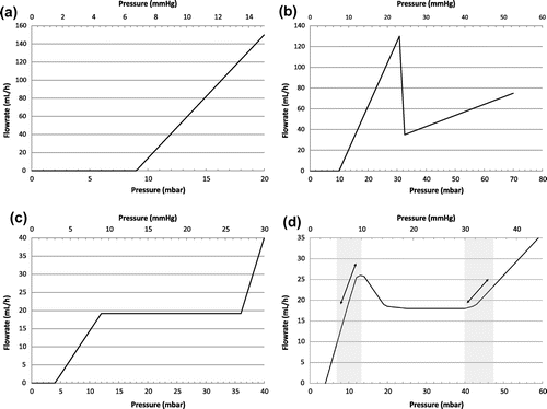
The flowrate vs. pressure characteristic of a typical differential shunt is provided in Figure (a). At equilibrium, the operating point of the device is determined by the production rate of CSF. In decubitus, the intracranial pressure (hereafter ICP) is here about 8 mm Hg for a production rate of 20 mL/h. Adjustable differential shunts exhibit the same resistance but the opening threshold is varied from 2 to 15 mmHg by mechanical means. The differential pressure ∆P inside the valve depends on the CSF derivation route: considering the peritoneum as reabsorption site, the expression of ∆P is:(1)
(1)
Figure 1. Typical hydrodynamic characteristic of a differential shunt (a), an antisiphoning shunt (b), a flow control valve (c) and a hybrid valve (d).
where HP is the hydrostatic pressure between the peritoneum and the valve and PP is the peritoneum pressure. In upright position, such devices lead to overdrainage and low ICP.
Antisiphoning (or antigravity) valves are associated with differential valves to limit the effect of postural changes on ICP. This device, which is usually placed in series with the differential valve, exhibits a high fluidic resistance above a predetermined pressure threshold, leading to a limitation of the overdrainage in upright position as illustrated in Figure (b) which shows the idealized hydrodynamic characteristics of an antisiphoning device (data extrapolated from Hashimoto, Mukai, & Tsukuda, Citation2004). In practice, large hysteresis is observed and the switching between low and high resistance pathway is unstable (Czosnyka, Citation2016).
Among the different valve mechanisms able to reduce the excessive CSF drainage related to postural change, as reviewed by Kurtom and Magram (Citation2007), a specific focus is made on devices exhibiting a variable fluidic resistance as shown in Figure (c) (from Chari, Czosnyka, Richards, Pickard, & Czosnyka, Citation2014). Several strategies have been used to obtain this variable fluidic resistance:
| • | A specific valve mechanism which consists of an elastomer diaphragm, a synthetic ruby seat inside the centre of the diaphragm and a notched pin (Integra™ Flow Regulating Valve OSV II). The top and bottom surfaces of the diaphragm are in direct communication with the proximal and distal catheters respectively. The diaphragm reacts to differential pressure variations. Any change of this differential pressure results in a change of the clearance between the seat and the pin. A specific design of the pin induces the typical hydrodynamic characteristic shown in Figure (c). | ||||
| • | A diamond-shaped slit in the silicone tubing that narrows at high pressure and limits the flow (e.g. CRx Diamond™ valve). | ||||
| • | A spiral-shaped channel engraved onto a piston, inside a hollow cylinder, that is pushed against a spring, inducing a linear increase of the length of this fluidic channel as the pressure increases (Chappel, Citation2016). | ||||
| • | A non-linear deformation of a silicon membrane having through holes that deflects under pressure against pillars, obstructing progressively the holes and limiting the flow (Chappel, Dumont-Fillon, & Mefti, Citation2014). | ||||
A hybrid valve characteristic is provided in Figure (d), with a nominal flow rate of 18 mL/h. This curve exhibits two pressure regulating areas between 5 and 10 mm Hg as well as above 30 mm Hg, corresponding respectively to the active areas in lying down and standing up positions. Thanks to the presence of the peak of flow rate at low pressure (see Figure (d)), short term fluctuations around the nominal value due to the vasogenic system, or inter-individual variations of production rate in the range 20 ± 4 mL/h, have a very limited impact on ICP value, even for patients having a very large resistance to CSF reabsorption (e.g. in case of obstructive hydrocephalus). For intermediate differential pressure in the valve, the device is equivalent to a flow regulator. This type of hydrodynamic characteristic equivalent to a mix between anti-gravity valve and flow control valve is made possible by the use of microtechnology. The microfluidic device described in Chappel et al. (Citation2014) is made of a stack of two plates: the first plate comprises a flexible silicon membrane having through holes while the second plate is a rigid substrate with a cavity, an outlet hole and pillars aligned with the through holes of the membrane. The liquid flows through the holes etched in the membrane and through the gap between the membrane and the pillars. Each hole can be considered as a valve which progressively closes as the differential pressure increases, leading to a non-linear fluidic behaviour. Hydrodynamic simulations associated with Finite Element Method simulations of the membrane deformation were carried out to design a device which delivers a constant flow rate. The hydrodynamic characteristic of the flow control valve characterized by Chappel et al. (Citation2014) does not exhibit a peak of flow rate at low pressure. To get this feature and to match the hybrid hydrodynamic profile, the design of the valve shall be modified. The increase of the flow rate at low pressure is simply obtained by increasing the diameter of the hole located near the centre of the membrane.
Since the fluidic resistance of flow control valve is large compared to classical differential shunts, the prediction of the evolution of the ICP is less intuitive. Hydrodynamic simulations have been carried out to better understand the impact of this hydrodynamic characteristic on ICP in various case studies, including inter-individual variations of the production or reabsorption rates, change of hydrostatic pressure and non-idealities in the hydrodynamic characteristic.
After a brief introduction of the CSF dynamic modelling tool, the results of the different simulations are shown, including a discussion about the impact of machining tolerances on the ICP control for flow control valves.
3. Modelling the CSF dynamics
Information about CSF flow and ICP are fundamental to diagnose and characterize cerebral diseases. The mathematical modelling of CSF flow has therefore been driven by this constant need to refine the analysis of the pressure monitored during infusion tests. In case of abnormal function of the cerebrospinal fluid outflow system, as reviewed by Pollay (Citation2010), several methods are used to diagnose hydrocephalus including the bolus injection test (Sokolowski, Citation1976). In practice, the constant-rate infusion test is the most frequently used: the mathematical modelling of the ICP rise after injection of a saline solution in the subarachnoid space has been described by Marmarou, Shulman, and Rosende (Citation1978). A review of the different improvements made to this initial model is proposed by Czosnyka, Czosnyka, Agarwal-Harding, and Pickard (Citation2012), Czosnyka, Czosnyka, Momjian, and Pickard (Citation2004), see also Clarke and Meyer (Citation2007) for a review of the history of mathematical modelling in hydrocephalus CSF dynamics. Other refined models are proposed by Smillie, Sobey, and Molnar (Citation2005), Raman (Citation2011) and Cieslicki (Citation2007). In the latter paper, fluctuations due to blood pressure and respiratory waves are introduced in the original Marmarou’s model of CSF dynamics which is summarized hereafter, in order to introduce the different notations. This analytical model has been used to validate the numerical modelling of the valve by shunting the valve.
We do not consider, in a first approximation, fluctuation due to periodic changes of the cerebral arterial blood volume and changes of venous outflow generated by respiration.
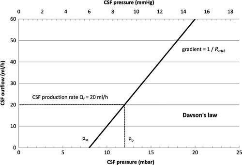
We assume a constant production rate of CSF. Therefore the production of CSF shall be balanced between storage and absorption. This absorption Qabs is proportional to the difference of pressure between the intracranial pressure p = ICP and the pressure in the sagittal sinuses pss (from Davson’s law, see Figure ):(2)
(2)
where Rout is the resistance to CSF reabsorption.
The storage of CSF is proportional to the cerebrospinal compliance C(p) and the rate of change of CSF pressure :
(3)
(3)
The compliance of the cerebrospinal space C(p) is constant up to a given pressure popt and decreases when the CSF pressure is larger than popt:(4)
(4)
where E is the cerebral elasticity or elastance coefficient which is patient specific. Because the craniospinal space is enclosed in the rigid skull, the compliance is small, typically between 0.1 and 0.3 ml−1 (Cieslicki, Citation2007). By writing the conservation of matter we obtain:(5)
(5)
where Qext(t) is the rate of external volume addition; the term , which is the baseline CSF pressure (resting pressure), is used in the latter formula instead of pss.
This equation could be solved easily in case of constant infusion rate test with . According to Marmarou, Shulman, and LaMorgese (Citation1975), Avezaat and van Eijndhoven (Citation1986), the evolution of the intracranial pressure for increasing volume has an exponential form.
We consider now a patient with a flow control valve that diverts the CSF toward the peritoneum. The equation of the conservation of matter becomes:(6)
(6)
where Qf is the formation rate of CSF, the absorption rate of CSF through the arachnoid villi,
the rate of liquid storage due to pressure changes and
the flow of CSF through the valve. We first assume that the compliance of the valve is very small compared to that of the brain itself. To simplify the formalism of the evolution of the pressure with time, we assume that the peritoneum pressure PP is equal to zero. The real gradient of pressure through the valve is reduced of about few mmHg in normal situation (typ. 1.5 mm Hg), even if CSF overdrainage into the peritoneal cavity may slightly change this nominal value.
A simplified model of the CSF dynamics using electrical equivalent networks is provided in Figure . The valve is modelled by a variable resistance in series with a diode (see e.g. Czosnyka, Cieslicki, Czosnyka, & Pickard, Citation2005). The classical equivalence between physical/fluidic effects and electrical ones is used as summarized in Table .
Figure 3. Simplified equivalent electrical model for CSF dynamics using a variable resistance valve to divert CSF toward the peritoneal cavity.
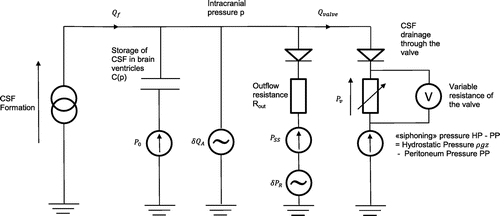
Table 1. Physical and/or fluidic effects and their electrical equivalents
At equilibrium, Equation (6) takes the form:(7)
(7)
Disequilibrium is then introduced in the model by a change of the production rate . To get a more realistic picture of the pressure trend, the change of the cerebral arteries volume δQA due to heart activity is also considered. It is assumed that this volume change is balanced by the same CSF volume fluctuations. Sagittal sinus pressure oscillations due to respiration are neglected here.
Therefore, the production rate of CSF includes an additional term in :
(8)
(8)
where ω1 is the heart rate angular frequency, CA the cerebral arteries compliance and δPA the amplitude of the sinusoidal perturbation, following the notation of Cieslicki (Citation2007):(9)
(9)
Changes in venous cerebral blood volume due to intrathoracic pressure variations lead to sagittal sinus pressure oscillations, around the mean value , at the respiration angular frequency ω2:
(10)
(10)
where δPR is the amplitude of the sagittal sinus pressure oscillations.
By combining (2), (4), (6) and (8), we get:(11)
(11)
Finally, after the introduction of the valve and a change in the nominal flow rate δQf, the differential Equation (5) describing ICP dynamics becomes:(12)
(12)
The different terms of the equations are introduced as variables in the numerical modelling. The hydrodynamic characteristics of the different valves, as shown in Figure (a)–(c), are modelled by numerical functions into a Matlab program. The pressure drop inside the valve is notably function of the siphoning pressure (see Figure ). Postural changes could also be introduced into the model through a time dependent hydrostatic pressure variable. A graphical interface allows a direct modification of the valve hydrodynamic characteristics, the simulation scenario (see e.g. Table ) and every parameter used to define the initial conditions (CSF production rate, ICP, peritoneal cavity pressure and other constants as defined in Table ). The evolution of the intracranial pressure over time is obtained by computing the infinitesimal change of pressure dP for each constant integration steps dt using Eq. (Equation12(12)
(12) ). The flow rate through each branch of the circuit shown in Figure can also be displayed.
Table 2. Simulation constants for modelling the ICP during an infusion test
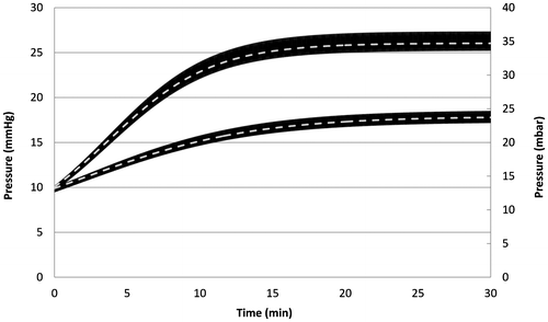
To validate the numerical model, a direct comparison has been made in Figure using the infusion test conditions provided by Cieslicki (Citation2007, p. 42). The equivalent electrical circuit has been simulated using the numerical constants given in Table .
Figure 4. Validation of the numerical model based on the comparison between the analytical Marmarou’s model (dashed lines) and the simulations based on the numerical resolution using electrical equivalent networks, for an infusion test at constant rates of 1 mL/min (bottom) and 2 mL/min (top) (high frequency oscillations appear as wide black lines due to the large difference between the infusion test duration and the oscillation period).
4. Simulation results for different hydrostatic pressures
To simulate the four different profiles shown in Figure (a)–(d), a CSF production rate of 20 mL/h has been considered. The effect of vasogenic pulsations on the ICP trend over such a long period has been simulated first. Since neither the hysteresis nor the compliance of the valve mechanism itself are considered here, in particular for devices having a flexible membrane, the main conclusions of the present study are not significantly affected by these pulsations, as long as their amplitudes remain within typical ranges (see e.g. values provided by Cieslicki (Citation2007)). Our simplified model only shows that the ICP oscillations are slightly smaller for differential shunts compared to flow control and antigravity devices. It has been decided, for sake of clarity, to use the following assumption: ω1 = ω2 = 0, the resulting ICP curves being centred in relation to the ones obtained without this simplification. The integration step dt has been increased to 6 s. A brief discussion about the impact of high amplitude waves is provided in the discussion.
Table contains the main parameters used for the simulations. The scenario described in Table consists of a wake up at 7 am (time 0) and a bedtime at 11 pm (time 0 + 16 h), considering a total test period of 24 h.
Table 3. Simulation constants for modelling the evolution of the ICP
Table 4. Description of the timing for the different postural changes
The evolution of the ICP for each type of device is shown in Figure (a)–(c), considering a hydrostatic pressure of 200, 300 and 400 mm of H2O respectively.
Figure 5. Simulated ICP according to the scenario of Table , for hydrostatic pressures of 200 mm (a), 300 mm (b) and 400 mm (c) of H2O.
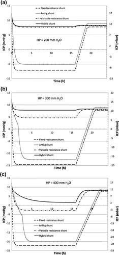
The antigravity shunt exhibits, as expected, a better capacity to prevent overdrainage for a short term period, when the patient wakes up, compared to a fixed resistance shunt. However the minimum value of the flow rate at high pressure (35 mL/h, see Figure ) induces a large negative ICP after a few hours. Even when reducing the minimum flow rate value to 20 mL/h, the presence of the huge peak at low pressure will prevent the stabilization of the ICP when the hydrostatic pressure varies, due to intermediate patient positions or patient growth). The small positive pressure PP in the peritoneal cavity slightly limits the siphoning effect. A mean value of +5 mbar for both supine and vertical positions is for instance reported by Freimann et al. (Citation2013) during careful measurements of the true intraperitoneal pressure in a porcine model, which provides physiological characteristics that are similar to those of humans. However, this mean constant pressure still being a subject of controversy, the value of PP is set to 0 for every test. As shown in Figure , the large peritoneal cavity compliance has not been included in the numerical model (typical PP increase is limited to about +2 mbar per litre of dialysate infused; see e.g. Durand, Chanliau, Gambéroni, Hestin, & Kessler, Citation1996). It is also important to note that the hysteresis of antigravity shunt has not been considered here.
The flow control valve is able to drain the ICP at the production rate without low ICP periods when the hydrostatic pressure matches perfectly the device characteristics provided in Figure (c) (HP < 250 mm H2O). For higher hydrostatic pressures overdrainage is observed. However, it is not occurring with the hybrid valve that significantly limits negative pressure periods in the brain ventricles.
5. Simulations of various CSF production rates
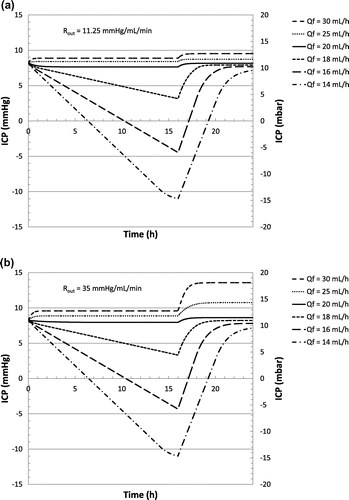
A second case study is considered. Based on the same scenario described in Table , a small change in the production rate is now simulated. Such a change is typically related to inter-individual variations of CSF production rate. Intra-individual changes are also possible: increase in the CSF production rate typically occurs for children or in case of haemorrhage, while a decrease could be observed for elderly people, especially in case of dementia of the Alzheimer’s type. CSF reabsorption resistance Rout is kept constant while the baseline pressure is adjusted to the new production rate (respectively +0.5 and −0.5 mm Hg). Hydrostatic pressure is fixed at 250 mm H2O in upright position. Classical differential-pressure valves are not strongly affected by such a change in CSF production or reabsorption rate. A specific focus has been made on flow control valves. Figure (a) and (b) show the evolution of the ICP considering a flow control valve as described in Figure (c), for a reabsorption resistance of 11.25 and 35 mm Hg min mL−1 respectively.
6. Simulations of non-idealities in the characteristic of flow control valve
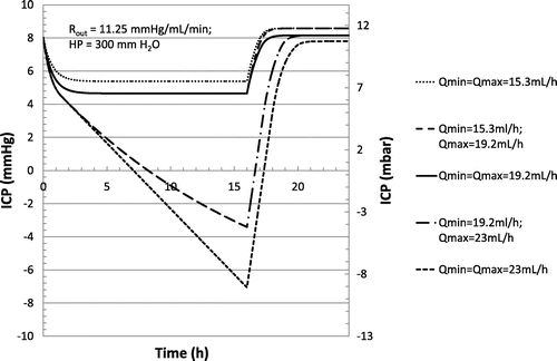
Non-idealities induced by manufacturing may change the shape of the hydrodynamic characteristic as well as the flow regulation range. Typical standard deviation observed experimentally for the mean regulation flow rate of flow control valve is equal to ±20% (Czosnyka, Czosnyka, Richards, & Pickard, Citation1998). Hysteresis leads to additional flow rate errors of the same amplitude (Czosnyka, Citation2016). According to the scenario of Table , numerical simulations of the change of the nominal flow regulation value as well as at the slope Q(P) have been carried out. The results are shown in Figure , for a nominal hydrostatic pressure of 300 mm H2O of water and a CSF production rate of 20 mL/h. Other simulation constants are provided in Table . The flow control valve regulates the flow in the typical pressure range of 9 to 27 mm Hg. We note respectively Qmin and Qmax the values of the flow rate at said pressures. Different shapes of hydrodynamic characteristics associated with flow control valves have been simulated according to the legend of Figure . It is shown that such non-idealities, even when considering flow rate errors at one sigma, could have a major impact on the stabilization of the ICP. The use of microtechnology for the manufacturing of flow control valves is therefore desirable to achieve flow rate accuracy with a standard deviation as low as only a few percent. In addition, flow control valves in silicon exhibit no hysteresis.
Figure 7. Simulated evolution of ICP over time using a flow control valve characteristic according to scenario of Table , at a production rate of 20 mL/h, a reabsorption resistance of 11.25 mm Hg min mL−1 and a hydrostatic pressure of 300 mm H2O, as a function of the hydrodynamic characteristic of the valve according to the different values of Qmin and Qmax reported in the legend.
7. Impact of the resistance to reabsorption on the functioning of flow control and hybrid valves
It could be noticed that such flow control valves may exhibit a permanent increase of ICP in decubitus in case of high resistance to reabsorption and CSF production rate larger that the nominal value.
To better explain the impact of the Rout value on ICP, for flow control valve, we consider the Equation (7), where the baseline pressure pb is in the flow regulation range of the Figure (c) for sake of simplicity. The introduction of an additional production rate δQf leads, at rest, to:(13)
(13)
As long as the ICP remains not too high (below about 27 mm Hg according to Figure (c)), the flow rate through the valve is constant, therefore
The increase of the ICP at equilibrium, in case of a change in the production rate, simply writes:(14)
(14)
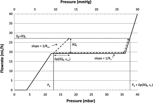
This linear increase of the ICP is illustrated in Figure . For small value of Rout, a flow control valve is able to drain CSF in a large range of production rates. For high value of Rout, underdrainage is expected according to the mechanism also depicted in Figure .
Figure 8. Schematic evolution of the ICP at high production rate for a flow control valve, for low (Rout) and high (R∞) resistances to CSF reabsorption.
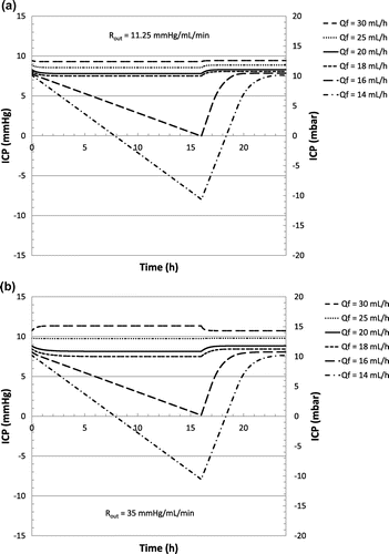
To verify that the hybrid valve exhibits comparable CSF drainage characteristics at low Rout values, the simulations provided in Figures (a) and (b) have been reproduced considering the hybrid valve (see Figure (a) and (b) respectively). Negative ICP values are only observed after 8 h in upright position, when the CSF production rate is as low as 14 mL/h, indicating that the hybrid valve is slightly more tolerant to low CSF production rate than the flow control valve. According to Figure (b), the permanent increase of ICP never exceeds 2 mm Hg in decubitus for the hybrid valve, considering CSF production rate as high as 30 mL/h.
Figure 9. Simulated evolution of ICP over time using the hybrid valve characteristic (as provided in Figure (d)) according to scenario described in Table , as a function of the production rate for a reabsorption resistance of 11.25 mm Hg min mL−1 (a) and 35 mm Hg min mL−1 (b).
For a reabsorption rate Rout ≥ 35 mm Hg min mL−1 a CSF formation rate of 24 mL/h is considered, using a hydrostatic pressure of 300 mm H2O. Except for the value of Rout, the numerical constants of Table apply. According to the scenario described in Table , the evolutions of ICP for the flow control valve (as described in Figure (c)) and the hybrid valve (as described in Figure (d)) as a function of Rout, are shown in Figure (a) and (b) respectively.
Figure 10. Evolution of the ICP for the flow control valve (a) and hybrid valve (b) for selected high reabsorption resistance values.
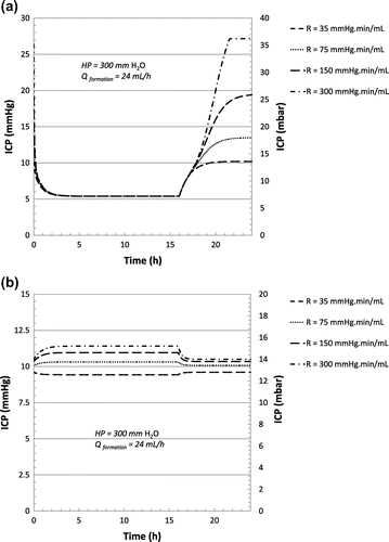
By contrast to the flow control valve, the hybrid valve is able to prevent underdrainage and therefore high ICP episodes in case of large resistance to CSF reabsorption (typically Rout ≥ 35 mm Hg min mL−1), considering CSF production rate of up to 24 mL/h. Following the mechanism described in Figure , the flow control valve induces a systematic increase of ICP if the CSF production rate exceeds the nominal drainage value of the valve (i.e. 19.2 mL/h for the valve described in Figure (c)) coupled with high reabsorption resistance values. Slow ICP waves of large amplitudes may lead to the same phenomenon. For large values of Rout, large oscillations of ICP are not compensated by reabsorption via normal routes and therefore, since the flow control valve having a flat characteristic drains at a constant rate Qcte, underdrainage occurs for production rates equal or larger than Qcte. Finally, it should be pointed out that a flow control valve made of a silicon membrane as disclosed in Chappel et al. (Citation2014) limits ICP fluctuations for both flat and wavy flow vs. pressure profiles (see Figures (c) and (d) respectively) because of the absence of hysteresis and its negligible mechanical compliance. More experimental data and an improved numerical model are needed to provide a realistic comparative study on the effects of large ICP oscillations due to the vasogenic system on the different types of valves.
8. Conclusion
Hydrodynamic simulations of hydrocephalus valves, based on the classical Marmarou’s model for CSF dynamics have been performed using electrical equivalent network. As reported in the literature, it has also been observed that differential or antisiphoning valves, which are by design insensitive to change in the production rate, are however less effective than variable resistance valves to prevent postural related overdrainage. The impact of non-idealities in the fluidic characteristic of flow control valve has been studied numerically, showing that the valve capability to prevent negative ICP episodes could be significantly reduced. The use of microtechnology to machine accurate valve mechanisms in silicon is therefore desirable. In addition, the investigation of more complex hydrodynamic profile is made possible, to address notably some inherent limitations of flow control valves in case of high resistance to CSF reabsorption. A hybrid hydrocephalus valve characteristic is proposed and its performances have been simulated and compared to other types of devices including both differential pressure and flow control valves. The valve is actually equivalent to the combination of two pressure regulators operating at low and high differential pressures, the device being able to switch automatically from one configuration to another as a function of postural change. Simulations in various case studies showed that a better tolerance to change of CSF production, hydrostatic pressure or reabsorption resistance would be expected. This hybrid valve characteristic should limit both overdrainage and underdrainage events and their negative side effects on patient’s health.
| Nomenclature | ||
| CSF | = | cerebrospinal fluid |
| p | = | value of the intracranial pressure (IPC) |
| p0 | = | pressure in the extradural venous system |
| pss | = | Sagittal sinuses pressure |
| pb | = | baseline ICP pressure, at rest in decubitus |
| = | flow through the valve at equilibrium | |
| Rout | = | fluidic resistance to CSF reabsorption towards physiological routes |
| ∆Preg | = | pressure range wherein the flow is almost constant (for variable resistance valve only) |
| PP | = | peritoneal cavity pressure |
| HP | = | hydrostatic pressure |
| ω1 | = | heart rate angular frequency |
| ω2 | = | respiration angular frequency |
| CA | = | cerebral arteries compliance |
Funding
This work was funded by Debiotech SA.
Acknowledgement
The authors would like to thank Pr M. Czosnyka (Neurosurgery Unit, Department of Clinical Neuroscience, University of Cambridge, UK) for fruitful discussions.
Additional information
Notes on contributors
E. Chappel
E. Chappel was born in Chambéry (France) and works as R&D project manager at Debiotech SA. He received a master degree in physics in 1996 (Université Grenoble Alpes) and accomplished his PhD thesis at French National High Magnetic Field Laboratory (Grenoble, 2000). His research interests are innovative medical devices, including insulin patch micropumps, hydrocephalus shunts, external ventricular drains, implantable pumps and on-body injectors.
References
- Aschoff, A., Kremer, P., Hashemi, B., & Kunze, S. (1999). The scientific history of hydrocephalus and its treatment. Neurosurgical Review, 22(2–3), 67–93.10.1007/s101430050035
- Aschoff, A., Wirtz, R., Hashemi, B., Unterberg, A., & Halatsch, M. (2007). Gravitational valves. Personnal 27 year experience in 420 patients. Cerebrospinal Fluid Research, 4, S1–S35.
- Avezaat, C. J. J., & van Eijndhoven, J. H. M. (1986). Clinical observations on the relationship between cerebrospinal fluid pulse pressure and intracranial pressure. Acta Neurochirurgica, 79(1), 13–29.10.1007/BF01403461
- Chappel, E. (2016). Design and characterization of a passive flow control valve dedicated to the hydrocephalus treatment. Cogent Engineering, 3(1), 1247612. doi:10.1080/23311916.2016.1247612
- Chappel, E., & Debiotech, S. A. (2017, September 6). Adjustable passive flow regulator. European Patent EP2943708B1.
- Chappel, E., Dumont-Fillon, D., & Mefti, S. (2014). Passive flow regulators for drug delivery and hydrocephalus treatment. In B.L. Gray & H. Becker (Eds.), Proc. of SPIE Microfluidics, BioMEMS, and Medical Microsystems XII (vol. 8976, pp. 89760S1-89760S11). San Francisco, CA. doi:10.1117/12.2036084
- Chappel, E., Neftel, F., & Debiotech, S. A. (2011, August 18). Passive fluid flow regulator. WIPO patent application 2011098867A1.
- Chari, A., Czosnyka, M., Richards, H. K., Pickard, J. D., & Czosnyka, Z. H. (2014). Hydrocephalus shunt technology: 20 years of experience from Cambridge Shunt Evaluation Laboratory. Journal of Neurosurgery, 120, 697–707.10.3171/2013.11.JNS121895
- Cieslicki, K. (2007). Mathematical modelling of the infusion test. Polish Journal of Medical Physics And Engineering, 13, 33–54.
- Clarke, M. J., & Meyer, F. B. (2007). The history of mathematical modeling in hydrocephalus. Neurosurgical Focus, 22, 1–5.10.3171/foc.2007.22.4.4
- Czosnyka, M. (2016, Februrary 29). Brain Physics Lectures [internet]. Cambridge: University of Cambridge. Retrieved from http://www.neurosurg.cam.ac.uk/pages/brainphys/
- Czosnyka, M., Czosnyka, Z., Agarwal-Harding, K. J., & Pickard, J. D. (2012). Modelling of CSF dynamics: Legacy of Professor Anthony Marmarou. Acta Neurochirurgica Supplement, 113, 9–14.10.1007/978-3-7091-0923-6
- Czosnyka, M., Czosnyka, Z., Momjian, S., & Pickard, J. D. (2004). Cerebrospinal fluid dynamics. Physiological Measurement, 25, R51–R76.10.1088/0967-3334/25/5/R01
- Czosnyka, Z. H., Cieslicki, K., Czosnyka, M., & Pickard, J. D. (2005). Hydrocephalus shunts and waves of intracranial pressure. Medical & Biological Engineering & Computing, 43, 71–77.10.1007/BF02345125
- Czosnyka, Z. H., Czosnyka, M., Richards, H. K., & Pickard, J. D. (1998). Posture-related Overdrainage: Comparison of the performance of 10 Hydrocephalus shunts in vitro. Neurosurgery, 42, 327–334.10.1097/00006123-199802000-00069
- Durand, P. Y., Chanliau, J., Gambéroni, J., Hestin, D., & Kessler, M. (1996). Measurement of hydrostatic intraperitoneal pressure: A necessary routine test in peritoneal dialysis. Peritoneal Dialysis International, 16(Suppl 1), S84–7.
- Freimann, F. B., Ötvös, J., Chopra, S. S., Vajkoczy, P., Wolf, S., & Sprung, C. (2013). Differential pressure in shunt therapy: Investigation of position-dependent intraperitoneal pressure in a porcine model. Journal of Neurosurgery: Pediatrics, 12, 575–581.
- Hashimoto, M., Mukai, H., & Tsukuda, T. (2004). Using the Codman® Hakim® programmable valve with SiphonGuard®. Neurosurg Bulletin, 14, 923–926.
- Kurtom, K. H., & Magram, G. (2007). Siphon regulatory devices: Their role in the treatment of hydrocephalus. Neurosurgical Focus, 22, 1–8.10.3171/foc.2007.22.4.6
- Marmarou, A., Shulman, K., & LaMorgese, J. (1975). Compartmental analysis of compliance and outflow resistance of the cerebrospinal fluid system. Journal of Neurosurgery, 43, 523–534.10.3171/jns.1975.43.5.0523
- Marmarou, A., Shulman, K., & Rosende, R. M. (1978). A nonlinear analysis of the cerebrospinal fluid system and intracranial pressure dynamics. Journal of Neurosurgery, 48, 332–344.10.3171/jns.1978.48.3.0332
- Pollay, M. (2010). The function and structure of the cerebrospinal fluid outflow system. Cerebrospinal Fluid Research, 7, 9.10.1186/1743-8454-7-9
- Raman, K. (2011). A stochastic differential equation analysis of cerebrospinal fluid dynamics. Fluids and Barriers of the CNS, 8, 9.10.1186/2045-8118-8-9
- Sainte-Rose, C., Hooven, M. D., & Hirsch, J. F. (1987). A new approach in the treatment of hydrocephalus. Journal of Neurosurgery, 66, 213–226.10.3171/jns.1987.66.2.0213
- Smillie, A., Sobey, I., & Molnar, Z. (2005). A hydroelastic model of hydrocephalus. Journal of Fluid Mechanics, 539, 417–443.10.1017/S0022112005005707
- Sokolowski, S. (1976). Bolus injection test for measurement of cerebrospinal fluid absorption. Journal of the Neurological Sciences, 28, 491–504.10.1016/0022-510X(76)90120-9

