 ?Mathematical formulae have been encoded as MathML and are displayed in this HTML version using MathJax in order to improve their display. Uncheck the box to turn MathJax off. This feature requires Javascript. Click on a formula to zoom.
Abstract
In this research paper a novel cascaded PD-Fuzzy-PID controller is recommended for a conventional hybrid-source unified power system for automatic generation control. The optimization of scaling parameters of the suggested PD-Fuzzy-PID controller is done by hybrid Grey Wolf Optimization-Teaching Learning Based Optimization (GWO-TLBO) technique. A sudden disturbance of 0.01 p.u. is considered in area 1 and ITAE is taken as the evaluative function in the recommended optimization process. The proposed work considers three different sources of generating systems namely, a hydro, a gas and a reheat thermal unit. Both AC tie-line and AC-DC tie-line is considered in analyzing the dynamic performances of the system. The robustness and sensitiveness of the proposed controller are further put to test for random load variations and nominal parameter variations. Analysis of the dynamic characteristics of the system is executed considering a number of time response specifications like settling time, peak overshoots and undershoots. During the analysis the optimum specifications obtained by the recommended technique are compared with some pre-published results in order to prove the supremacy of this novel controller over existing controllers. Further, the frequency stability of the system is improved by employing an UPFC in the system.
Public Interest Statement
Due to the progressive increase in the size of the power system, the necessity of keeping the frequency and tie-line power within recommended limits has become a major concern. So this is a challenge for the engineers to keep the power system consistent and secure. This article proposed a novel PD-Fuzzy-PID cascaded controller for automatic generation control of an interconnected power system which helps in maintaining the frequency and tie-line power deviations in the system within specified limits. By the introduction of such controller the frequency deviation in the interconnected power system can be regulated in a better way which in turn balances the net generation in accordance to the demand.
1. Introduction
Due to the progressive increase in the size of the power system, the obligation of keeping the frequency and exchange of tie-line power inside recommended restrictions has become inevitable. So this becomes a challenge for the engineers to keep the power system consistent and secure. Power system all over the world has now become interconnected, i.e. small individual units of power system gets joined with each other using tie-lines forming a unified area. There is a compulsion of maintaining the deviations in system constraints within specified limits, with the purpose of preserving the stability of the power system. AGC in each area plays a major role by examining the frequency and the tie line power. It balances the net generation in accordance to the demand. The nullification of system error can be done by regulating Area Control Error which is the actuating signal for AGC. AGC operates to meet the demand in a specified area with random changes in the load in a controlled manner. It wishes to regulate the frequency and inter-area power flow close to prescribed values (Kundur, Citation1994).
A thorough and extensive research has been done over the past years on various control strategies of AGC in order to maintain system deviations within prescribed limits during normal and abnormal operating conditions. Classical methods of frequency and inter-area power control were first proposed in 1957 (Cohn, Citation1956). In this paper the various load curves were explained and the problem was solved with the help of a numerical example. The concept of multi area modelling for the AGC technique of the interconnected area is proposed in (Kothari & Nanda, Citation1988). Y. Wang described the single area power system scenario and applied AGC using generation rate constants (GRC) in paper (Wang, Zhou, & Wen, Citation1994). K. R. Mudi and R. N Pal, in the paper (Mudi & Pal, Citation1999), described a self-tuning scheme optimized fuzzy logic controller which is simple but robust in nature. For a smoother control of frequency, apart from the speed control of the governor, the concept of a secondary control using PI controllers was proposed in (Nanda, Mangla, & Suri, Citation2006). In (Nanda, Mishra, & Saikia, Citation2009) J Nanda et al. explained the bacteria foraging based AGC in multi-area interconnected power system. A comprehensive comparison of various classical controllers and their performance evaluation for thermal system having a multi-area was aptly presented in (Nanda & Saikia, Citation2008). The concept of a robust PID controller for LFC was first proposed in (Shabani, Vahidi, & Ebrahimpour, Citation2013). With a greater efficiency fractional order controller was efficiently used in (Alomoush, Citation2010) for load frequency control. The effectiveness of the controller is governed by the time taken by the ACE to come to zero. This depends upon the proper extent of optimization of the controller gains. Earlier methods of setting these gains were traditional hit and trial methods. These classical methods were time consuming and less efficient. With the successful research on Meta-heuristic optimization techniques and bio-inspired computational schemes, the controller gains can now be properly optimized. Various bio-inspired computational schemes came into existence like Particle swarm optimization (PSO), bacterial foraging algorithm (BFOA), differential evolution technique (DE) and a lot more. The researchers focussed on the application of these techniques to optimize the controller gains. The concept of Load Frequency Control optimized by Genetic Algorithm (GA) in fuzzy rule was proposed in (Ghoshal & Goswami, Citation2003). The first application of Particle Swarm Optimization (PSO) technique along with fuzzy rule base for the AGC is clearly described in (Ghoshal, Citation2004). The implementation of HVDC lines and the study of AGC using optimal regulators was aplty described in (CitationSingh & Nasiruddin, 2016). Use of an adaptive fuzzy logic approach for the load frequency control of the multi source power system was effectively elaborated in (Yousef et al., Citation2014). In paper (Mohanty, Panda, & Hota, Citation2014a) the Differential Evolution technique was used for frequency regulation for unified systems with non-linearities. Paper (Khuntia & Panda, Citation2012) puts to picture the simulation study of AGC using ANFIS (Artificial Neuron-Fuzzy Inference System). Application of various FACTS devices and SMES (Superconducting Magnetic Energy Storage) in conventional power system for AGC was portrayed by Barisal et al. in (Lal & Barisal, Citation2017). Hybrid evolutionary algorithm based fuzzy logic controller for automatic generation control of power systems with governor dead band non-linearity was effectively proposed in (CitationSingh & Nasiruddin, 2016) by O. Singh et al. The implementation of optimal Gravitational search algorithms for tuning the controller parameters for the AGC of an interconnected power system is put effectively in (CitationSahu, Panda, & Padhan, 2014). Differential evolution as the computation technique to tune the controller gains in the AGC of an interconnected power system was analysed effectively in (Rout, Sahu, & Panda, Citation2013). R K Sahu, S. Panda in their research paper (Rout et al., Citation2013) has clearly described a hybrid optimization technique with firefly algorithm and pattern search algorithm for AGC in unified power systems. Paper (Ismayil, Kumar, & Sindhu, Citation2015) defined Genetic Algorithm based fractional order PID controller for AGC of a two area power system. In article (Manoj Kumar Debnath, Mallick, & Aman, Citation2016), Gravitational Search Algorithm is used for tuning Fuzzy-PID controller for load frequency control in an unified two area power system. The concept of Teaching and Learning Based Optimization (TLBO) was first introduced in the paper (Rao, Savsani, & Vakharia, Citation2012). A new optimization technique known as Grey Wolf Optimizer was introduced in (Mirjalili, Mirjalili, & Lewis, Citation2014). In (CitationSahu, Gorripotu, & Panda, 2016) R. K. Sahu et al. applied the TLBO optimization technique for AGC using Proportional-Integral-Double Derivative (PIDD) controller. Most recent optimization technique, i.e. the Grey Wolf Optimization technique is successfully implemented for Load frequency control of a multi area Power system by Dipayan Guha, Provas Kumar Roy and Subrata Banerjee (Guha, Roy, & Banerjee, Citation2016). In paper (CitationSahu, Pati, & Panda, 2014) the authors have clearly illustrated the hybrid DE-PSO technique for frequency regulation in a hybrid source power system. In (Mohanty, Panda, & Hota, Citation2014b) the AGC was carried on a hybrid source power system using the differential evolution algorithm. A hybrid LUS-TLBO (Local Unmoral Sampling-Teaching Learning based optimization) tuned Fuzzy-PID controller has been proposed successfully in (CitationSahu, Pati, Nayak, Panda, & Kar, 2016) for AGC of hybrid-source power system. P.C. Pradhan and et al. have proposed frequency control in hybrid-source systems with UPFC and SMES considering firefly algorithm (Pradhan, Sahu, & Panda, Citation2016). Paper (Arya, Citation2017) effectively portrays the use of a new fractional order fuzzy PID controller to enhance the performance of the system. The gains of the controller as well as the Fuzzy scaling factors were optimized by ICA (imperialist competitive algorithm) and the effectiveness is successfully established. Thereafter, many techniques have been proposed in the multi-source system including redox flow batteries (Arya & Kumar, Citation2016a) for automatic generation control. In paper (Arya & Kumar, Citation2016b) AGC of a multi-source sytem is performed under deregulated environment. Y. Arya (Arya & Kumar, Citation2016c) proposed a novel controller called Fuzzy gain scheduling controller for AGC of a two area nonreheat thermal system. Paper (Padhy, Panda, & Mahapatra, Citation2017) portrays a modified GWO technique based cascade PI-PD controller for AGC of power systems in presence of Plug in Electric Vehicles. In paper (El-Hameed & El-Fergany, Citation2016), Load frequence control of a multi-area system using water cycle algorithm based PID controller was effectively analysed. Paper (Ou & Hong, Citation2014) analyses the operation and control of a microgrid comprising of wind power system, photovoltaic source and fuel cell. Paper (Ou, Lu, & Huang, Citation2017) applied a novel intelligent damping controller (NIDC) for the static synchronous compensator (STATCOM) to reduce the power fluctuations, voltage support and damping in a hybrid power multi-system. In paper (Ou, Citation2012) a novel unsymmetrical faults analysis for microgrid distribution systems was discussed. Paper (Ou, Citation2013) deals with the Ground fault current analysis with a direct building algorithm for microgrid distribution.
From the Literature survey, it becomes clear that a large number of research works were developed using a single control loop, but in our present work emphasis is given to the development of two control loops. In this regards the objective of the present research work can be summarized as follows.
| (a) | Designing novel cascaded PD-Fuzzy-PID controller and implementing in a conventional hybrid-source power system for frequency regulation. | ||||
| (b) | Applying hybrid GWO-TLBO algorithm to get the optimum values of the recommended controller parameters of the hybrid-source power system with AC link and AC-DC link. | ||||
| (c) | Evaluating the dynamic performance of the system and comparing this with pre-published results so as to establish the supremacy of the recommended controller. | ||||
| (d) | Proving the robustness and sensitiveness of the system by varying the load of the system randomly, also by varying the parameters of the system. | ||||
| (e) | Improving the frequency stability of the system by employing an UPFC in the system. | ||||
2. System examined
In this research analysis three types of generating sources are implemented in each area of a two area unified power system. The generating sources include a gas unit, a thermal unit with reheat turbine and a hydro unit. The parameters of the system are taken from previously published research work (Sahu et al., Citation2016) listed in the Appendix A. Figure displays the linearized model of the proposed work. The dynamic performance of the system is investigated considering an SLP of 1% (0.01pu) applied to area 1 only. Initially the system peformances are investigated in two cases, without and with HVDC link. Then the system behaviour is examined with the inclusion of UPFC. Each area has a distinct PD-fuzzy-PID cascaded controller for maintaining the variations in frequency and tie-line power. While regulating the system deviations, the ACE is also minimized. The ACE for each areas is expressed as(1)
(1)
(2)
(2)
Figure 1. The hybrid-source power system model (Sahu et al., Citation2016) represented by transfer functions.
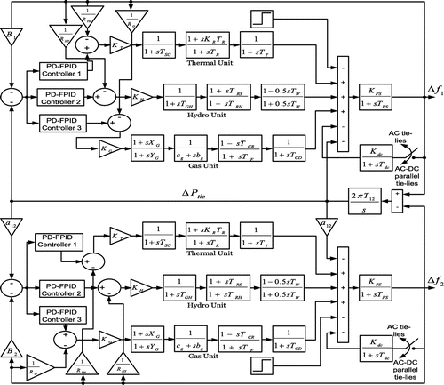
where ΔPtie is the interline power variation between both the areas, B1 and B2 are frequency bias coefficients of respective area. Δf1 and Δf2 are frequency variations in respective area.
3. The proposed optimization algorithm
3.1. Grey wolf optimization technique
Brought to picture in 2014 by Mirjalili et al. (Citation2014), this algorithm draws its inspiration from the social behaviour and the leadership hierarchy of the grey wolves. Grey wolves (Canis Lupus) are the member of the Canidae family and belong to the topmost level of the food cycle. They are also referred as the apex predator. The wolves mainly prefer to survive in a group (pack) and the number of members in a pack is on an average 5–12. Each and every such pack of wolves exhibits a social dominant hierarchy among them. Of each group a male and a female is taken as a leader named as alphas. The alphas are mainly responsible to take important decisions in a group. Whatever decisions the alphas take, they are strictly followed by the entire group. However there are some democratic traits in each group which is also maintained because in many situations it has been seen that the alphas follow the rest of the pack. The alphas are the most dominant in the group though they are not the strongest in the pack. The dominance of alpha is governed by its managerial capacities.
The next hierarchy in the pack is the betas. The beta wolves are subordinate to the alphas and they aid the alphas in the entire decision-making and the managerial decisions. The beta wolves are also most apt to take over the position of the alphas when they pass away. The beta wolves obey the alpha but rule over the bottom layer of the pack. It acts as an advisor for the alpha and plays a disciplinary role for the rest of the pack. All the major decisions of the alpha are conveyed to the rest of the pack with the help of beta.
The last tier of this hierarchical structure is the omegas. The omegas are the least dominant members in the group and acts as a scapegoat to the dominant wolves. All the frustrations and the anger of the upper tier of wolves are vented out through these weak wolves and they are permitted to eat last.
Apart from the above three tiers there are wolves who are not alpha neither beta neither omega. They are sometimes referred to as the deltas. They are dominated by the alphas and the betas but they rule over the omegas. They mainly belong to the caretaker and the sentinel post of the pack. The methodology of predation is categorized as follows:
| (i) | Tracking, racing and approaching the prey. | ||||
| (ii) | Encompassing and stepping towards the prey. | ||||
| (iii) | Attacking the prey. | ||||
In the above expressions the parameters and
are expressed as
(5)
(5)
(6)
(6)
“t” stands for the current iteration and the coefficient vectors are represented by and
.
is the current wolf position. The Grey wolves are known for their unique ability to assess the location of the prey and devour them. The alphas predominantly guide the act of hunting. The positions of other wolves towards the prey are updated according to the position of alpha, beta and delta. The hunting property of alphas, betas, deltas and their position updation can be mathematically expressed as:
(7)
(7)
(8)
(8)
(9)
(9)
(10)
(10)
(11)
(11)
(12)
(12)
(13)
(13)
The steps of the GWO algorithm are proposed below:
| (i) | Initialization: A population of wolves is initialized randomly as xi (i = 1, 2, 3 … n) based on the upper and lower bounds of the variables. The parameters a, A and C are also initialized. | ||||
| (ii) | Objective function: The objective function f(x) is properly chosen to calculate the corresponding objective value or the fitness value for each wolf. | ||||
| (iii) | The choice of the best search agent: A proper choice for the first three wolves are done and is saved as Xα, Xβ and Xδ. | ||||
| (iv) | Iteration: The stopping criterion is taken as while (t < Maximum Generation) | ||||
| (v) | Update the position of each search agent in accordance with equation (Equation13 | ||||
| (vi) | Update Xα, Xβ and Xδ. | ||||
| (vii) | Update the parameters a, A, and C | ||||
| (viii) | The value of Xα is returned as the best value. | ||||
| (ix) | The above process continues till the stopping criterion is encountered. | ||||
3.2. Teaching and learning based optimization
This well-known optimization technique was developed in recent years based on the teaching-learning process inside a classroom (Rao et al., Citation2012). To get the optimum results this optimization algorithm also employed population based computation like other optimization algorithms. The explanation of the algorithm is mainly achieved by two tiers: teaching phase and learning phase.
Socially the most educated cluster of people is identified as teachers. By getting knowledge from the teachers, the learners try to improve their talents. In this optimization process teacher acts as a best solution for the next population.
The operation of the TLBO algorithm takes part in the following stages:
Stage 1: Initialisation:
Initialisation of Parameters like random population, population size, number of students (solutions), and number of iterations required for termination of the process and the other design variables along with their respective ranges are done in this stage.
Stage 2: A proper decision of the objective function is made. Each and every member acquires a fixed value of fitness, denoting the grade or marks obtained by the students.
Stage 3: This stage is called the Teacher Phase: In this phase the updation of the existing solution based on the best value of the fitness function is done. The solution updation is done by the following formula:(14)
(14)
where the value of Difference\meanis obtained as(15)
(15)
and teaching factor TF is calculated as(16)
(16)
Now if f(Xnew,i)〈f(Xi) then Xi = Xnew,i
Stage 4: This phase is called the learners phase. In this phase the following procedure is implemented to update the solution. The value of the fitness function so obtained helps in the updation of the existing solution. The details of the learner phase is given below.
Randomly select two learners Xi and Xj such that j ≠ i.
If f(Xi)〈f(Xj) Then(17)
(17)
Else(18)
(18)
Now if then
Stage 5: Check the stopping condition. If satisfied, return the best result otherwise go to nest iteration.
3.3. Hybrid GWO-TLBO algorithm
From the explanation of GWO algorithm it is clear that the updation of the search agent in GWO is governed by the location of alpha, beta and delta wolves. Thus encircling, hunting and attacking are the basic and simple operators in GWO algorithm which are used to get optimum solution. But with these operators the GWO algorithm seems to be trapped in local optima. Thus GWO algorithm has a major disadvantage that it has less exploration which can be emphasized by the inclusion of more operators. On the other hand TLBO is a population based optimization which is capable of producing global optimum solution through teacher and learner phases. Thus TLBO provides more exploration and exploitation capabilities. In order to extract the best of two algorithms (GWO and TLBO) the hybrid GWO-TLBO algorithm is proposed here. The basic steps followed to develop this hybrid algorithm are laid below.
| (i) | Initialize a random population X1 based upon the limit of search space. | ||||
| (ii) | Apply GWO operators and get the updated population X2. | ||||
| (iii) | Take the final population of GWO i.e. X2 as the initial population for TLBO. | ||||
| (iv) | Apply TLBO operators and get the updated population X3. Accept the population X3 it is better than previous population X2. | ||||
| (v) | Check for the stopping condition. If satisfied, return the best result of the last step, otherwise go to the next iteration (step.ii). | ||||
4. Control methodology
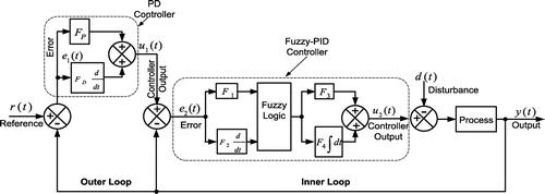
In this proposed work a cascaded PD- Fuzzy-PID controller is used. Three such controllers are implemented for three different sources in each area. Figure vividly describes the configuration of the proposed controller. The figure clearly states that each PD-Fuzzy-PID controller consists of six scaling factors indicated by LP, LD, L1, L2, L3 and L4. The thermal unit, the hydro unit and the gas units have six different values of scaling factors. The main complication thereby lies in the optimization of total eighteen parameters and assigning them suitable values. The hybrid optimization technique called GWO-TLBO has been implemented for the optimization of the scaling parameters and finally minimizes the frequency and tie-lien power deviations. The prime objective of introducing a cascaded controller is the mitigation of the disturbance within a very short span of time and prevents it from traversing to the other part of the system. Each cascaded controller consists of two loops:
Outer loop: Also named as the master loop, it contains the proportional-derivative controller having parameters LP and LD. The input to this controller is the area control error denoted by r(t).
Inner loop: Also named as the secondary or the slave loop, it contains the Fuzzy-PID controller consisting of parameters L1, L2, L3 and L4. The outer PD controller feeds its output to the inner Fuzzy-PID controller. Also for this inner Fuzzy-PID controller the change in output frequency is given as the feedback signal. The prime objective of the inner loop is to restrain the effect of the gain variations on the system performance. The gain variations may usually arise due to the shifting in operating points which can be accounted by set point changes or sustained disturbances.
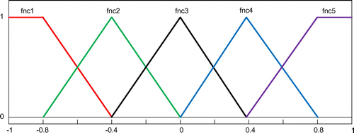
The Cascaded controller has a greater advantage than the normal controller in terms of an increased speed of response and minimization of the system disturbances by correcting it within the system. In this proposed work the control scheme is designed with an inner Fuzzy-PID loop and an outer PD control loop. The main important section of a Fuzzy-PID controller is fuzzy logic section. The distribution of the fuzzy rules along with the membership function stands as the main hindrance of a fuzzy logic controller. The precision of fuzzy logic controller is mainly governed by the selection of the fuzzy rules provided by the expert. This paper has taken the assistance of the popular mamdani fuzzy inference system for producing the control output. The output of the inference system is fuzzy, which is converted to real valued data with various defuzzification processes. Here we have used center of gravity (COG) method to get defuzzified output. For simplicity and effective computation five triangular membership functions named as fnc1, fnc2, fnc3, fnc4 and fnc5 are being used in the inference system for input and output fuzzy variables which is shown in the Figure . Corresponding to five membership functions twenty-five “If Then” rules are developed. Table lists down the proposed fuzzy IF THEN rules.
Table 1. Fuzzy Rule-base of fuzzy inference system
5. Result and analysis
In this proposed work a hybrid GWO-TLBO algorithm has been effectively implemented to design the optimal PD-fuzzy-PID controller. The multi-source system is modelled in Matlab/Simulink environment using Matlab version 7.10.0(R2010a). The hybrid GWO-TLBO algorithm is written in Matlab script file for optimization of the system parameters. The size of the population and maximum iteration, each taken as 100 for the optimization process. The Integral Time Absolute Error is taken as a time dependent objective function in this case. This ITAE objective function is expressed as follows.(19)
(19)
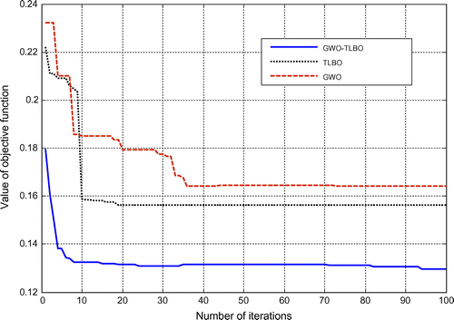
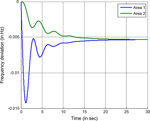
By considering this objective function the proposed algorithm is simulated using Matlab. The gains of the PD- Fuzzy-PID controller have been optimized for two different cases, both in the presence and absence of AC-DC link. The dominance of the system is established by comparing the dynamic response of the system with pre published results like DE optimized PID controller (Mohanty et al., Citation2014b) and LUS-TLBO optimized Fuzzy-PID controller (Sahu et al., Citation2016). The convergence characteristics for TLBO, GWO and Hybrid GWO-TLBO methods are plotted in Figure to ensure that proposed hybrid optimization technique provides better convergence as compared to others. In order to show the necessity of the controller in the interconnected system the system is initially simulated without any controller and the deviations of frequency in each area is observed as shown in the Figure . From this figure it is clear that the frequency variation of the system never attains the steady state value (“0” level) which is very dangerous for the system. So in order to overcome these problems regarding instability and to improve the performance of the system and to settle the deviation at “0” level (steady value), the need for a controller comes into account. The various case studies involved in this work are discussed below.
5.1. Performance evaluation of the scrutinized system without the HVDC link
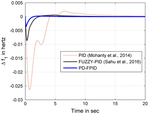
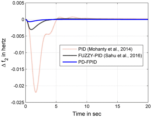
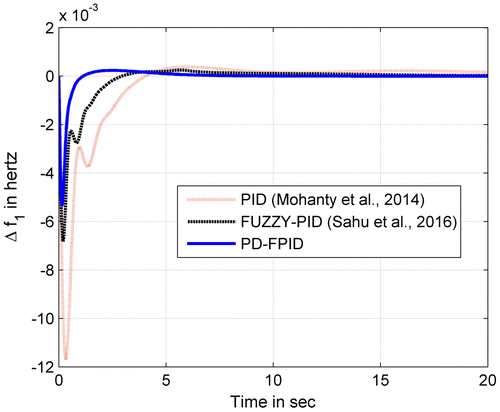
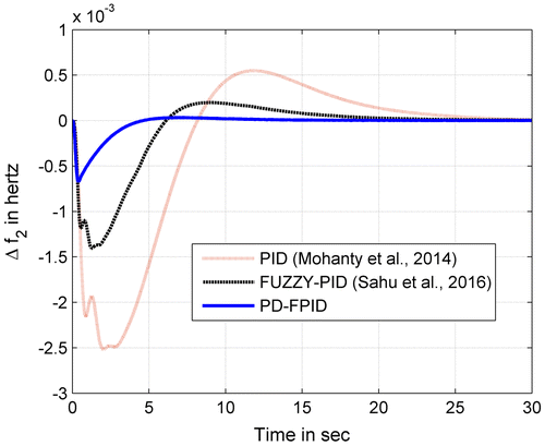
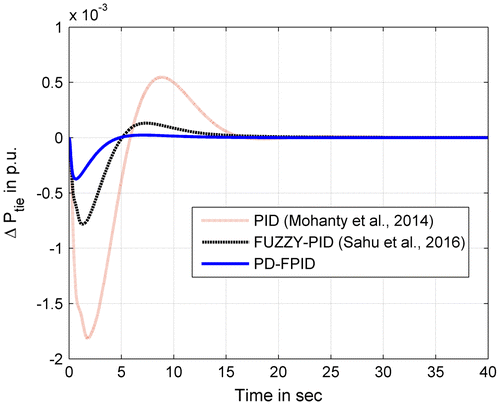
In the first case, Ac tie-line is placed between the two areas to examine the dynamic behaviour of the hybrid-source system subjected to a SLP of 0.01p.u. in the area 1. Under this condition the hybrid GWO-TLBO algorithm is used for the optimization of the gains of the proposed PD-Fuzzy PID controllers. The optimized controller gains are defined in Table . The finest controller gains are utilized to plot the frequency and interline power variations of the system. Figure (a) and (b) illustrate the frequency variations of the first area and the second area
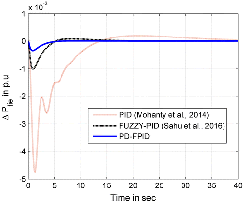
respectively. Figure (c) demonstrates the interline power variations
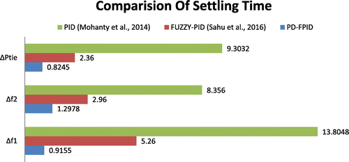
between both the areas. These plots are superimposed and compared with the previously published results to prove the supremacy of the recommended method. Plotting specifications like minimum undershoots
, settling time
(for 0.05% band) and peak overshoots
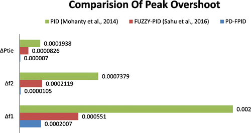
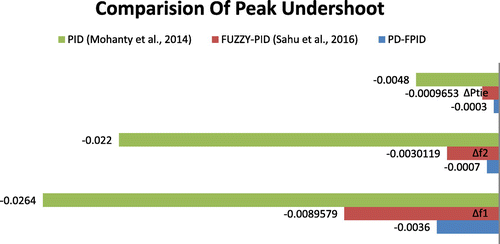
are recorded in Table . A bar graph indicating the settling time, peak overshoots and undershoots of the proposed work is plotted in the Figure (a), (b) and (c) respectively showing the superiority of the proposed method. Table portrays the improvement in the dynamic response characteristics of the system. This table also clearly proposes that the suggested method gives superior result as compared to the DE optimized PID controller (Mohanty et al., Citation2014b) and LUS-TLBO optimized fuzzy-PID controller (Sahu et al., Citation2016).
Table 2. Scaling parameters of different controllers with AC link only
Table 3. Settling time, peak overshoots and undershoots of the response considering AC tie-lines only
Table 4. Percentage improvement in settling time, peak overshoots and under shoots with AC tie-lines only
5.2. Analysis of the scrutinized system with HVDC link
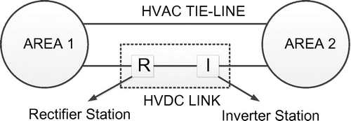
In this case the power system is extended to high voltage DC transmission along with the high voltage AC. HVDC has its major advantage of simplifying the connection of various control areas without the problem of synchronization. The power transfer capability of the system is also increased because of the use of HVDC transmission. The inclusion of HVDC link also increases the dynamic performance of the system when it is subjected to small disturbances. Figure shows the connection of HVAC and HVDC line between two areas interconnected power system. In this analysis we included the transfer function model of HVDC system which is shown in Figure . The controller parameters are optimized here with HVDC link by applying sudden load perturbations of 0.01p.u. in area 1. The best outcomes of the recommended PD-fuzzy-PID controller factors are listed in Table . The variation of frequency of area 1 , area 2
and the interline power deviation between area 1 and area 2
are shown in the Figure (a), (b) and (c) respectively. Settling time
(for 0.05% band), peak overshoots
and undershoots
are computed for all the methods under this scenario and are listed in Table . Observing the percentage improvement of the dynamic response specifications in Table , It can be determined that the recommended control technique produces better results as compared to the pre published results (Mohanty et al., Citation2014b) and (Sahu et al., Citation2016).
Table 5. Scaling parameters of different controllers with HVDC link
Table 6. Settling time, peak overshoots and undershoots of the response considering AC-DC tie-line
Table 7. Percentage improvement in settling time, peak overshoots and undershoots with HVDC link
5.3. Analysis of the scrutinized system without HVDC link under change in SLP
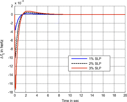
The sturdiness of the system is examined by increasing the SLP in area 1 by 0.01 p.u. The dynamic performance of the system is studied under the effect of SLP in area 1. The multi-source system having an AC tie line is periodically scrutinized with 1, 2 and 3% SLP in area1. The variations in frequency in area1 for 1, 2 and 3% SLP in area1 are clearly depicted in the Figure . The figure clearly demonstrates that the performance stability of the system remains intact even if we change the size of the disturbance.
5.4. Analysis of the scrutinized system without HVDC link under parameter variations
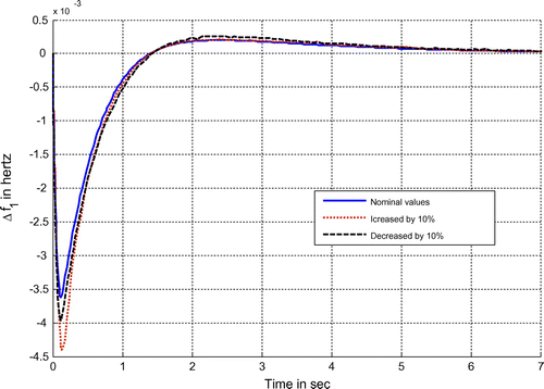
The specified values of parameters of the multi-source system are considered from the appendix (Sahu et al., Citation2016).The system is further put to test by increasing and decreasing all the time constants of the systems by 10%. Under such conditions the deviation of frequency in area 1 is presented in the Figure . It is observed that the system stability remains unaffected even if the time constant parameters of the system are changed. In order to show the robustness, all the time coefficient parameters are perturbed in a step of 20% and the corresponding values of settling time, peak overshoots and undershoot for frequency deviations
and
are itemized in Table . This table justifies that even after changing the parameters of the system, there is no significance change in the time response specifications which in turn reflects the superior behaviour of the proposed controller.
Table 8. Variations of settling time, peak overshoots and undershoots due to parameter variations
5.5. Analysis of the system without HVDC link under random loading condition
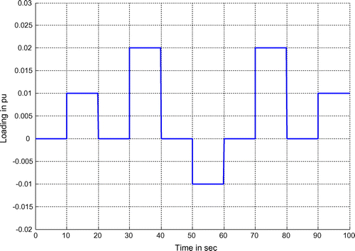
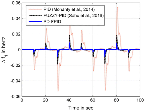
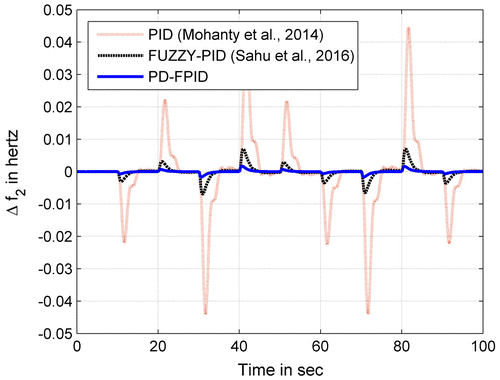
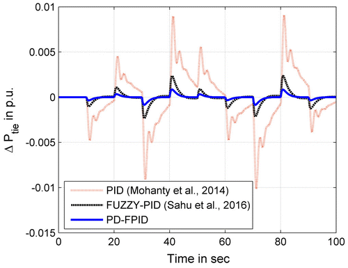
Further the analysis of the proposed system is extended by applying random loading in area 1. The pattern of random loading is shown in the Figure (a). With this random loading, the frequency deviations and
, tie-line power deviations
are shown in Figure (b), (c) and (d) respectively. These figures justify the capacity of the proposed controller to maintain stability even after random load changes.
5.6. Performance indices of proposed system without HVDC link
The supremacy of the proposed control scheme is tested by computing the values of various performance indices of the system (with AC tie-line only) namely integral absolute error (IAE), integral time absolute error (ITAE), integral squared error (ISE) and integral time squared error (ITSE). The system performance increases if the value of these performance indices decreases. These performance indices are defined below.(20)
(20)
(21)
(21)
(22)
(22)
(23)
(23)
The values of these performance indices are listed in Table for various control techniques. It is clear from the table that the values of these performance indices are less for the proposed hybrid GWO-TLBO optimized PD-Fuzzy-PID controller as compared to other methods.
Table 9. The value of various performance indices
6. Modelling the system with UPFC
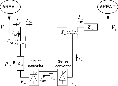
UPFC is one of the most widely accepted FACTS devices and is employed to improve the power flow in power system in a more flexible way. This power electronic based device is mainly used to improve the power transfer capability, the power quality issues and the transient stability in the power system. The connection of UPFC in a two area system is shown in the Figure (a). Here Vs, Vr and Vse represents the sending end voltage, receiving end voltage and series compensated voltage respectively. The shunt converter adjusts the suitable value of the shunt branch current by injecting suitable shunt voltage Vsh such that the real power demand of series converter is fulfilled. The series compensated voltage Vse can be adjusted both by the magnitude and angle so that the complex power at the receiving end can be controlled. From the figure the complex power at the receiving end can be expressed as(24)
(24)
From the expression, it is clear that Vse = 0 corresponds to an uncompensated system. In this case the UPFC is mainly used in association with the tie-line in order to improve the frequency profile of the system. The transfer function of the UPFC controller employed in AGC (Pradhan et al., Citation2016) can be expressed by(25)
(25)
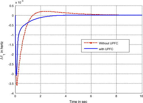
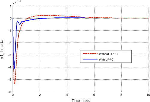
Where TUPFC stands for the time constant of UPFC. ΔF(s) indicates the change of frequency, acts as input to the UPFC and ΔPUPFC(s) indicates the power variation introduced by UPFC in the tie-line, acts as output of the UPFC. The UPFC is placed in multi-source system for both conditions, i.e. without HVDC link and with HVDC link. In the first case with the existing controller gains of suggested PD-Fuzzy-PID controller and AC tie-line, UPFC is placed in series with tie line (Pradhan et al., Citation2016) and frequency deviations are examined. The Figure (b) represents the frequency deviations of area 1 under such conditions which reveals that with the placement of UPFC the frequency deviations is being improved in consideration of settling time, peak overshoots and undershoots. In the second case the analysis is carried on the multi-source system with HVDC link and UPFC and the frequency deviations of area 1 is depicted in Figure (c), which again assists the improvement of the results.
7. Conclusion
The hybrid GWO-TLBO technique is successfully employed in this research article to get the finest factors of the novel PD-fuzzy-PID cascaded controller for automatic generation control of the conventional hybrid-source unified power system. Hybrid GWO-TLBO algorithm took the advantages of both GWO and TLBO techniques in order to obtain minimum fitness value. The developed hybrid GWO-TLBO technique is applied to tune the PD-fuzzy-PID cascaded controller in the system without and with HVDC link. The system responses are examined by considering the previously published results like DE optimized PID controller and LUS-TLBO optimized fuzzy-PID controller. With reference to the time response indices like minimum undershoots, settling time and maximum overshoots, the supremacy of the proposed method is established. The robustness and sensitivity of the system is analysed by changing the size and position of SLP. Thereafter, the system robustness is also checked by varying the parameters of the system and by applying random loading in the system. Finally, the system dynamics are evaluated with an UPFC in the system which again affirms the superiority of the suggested controller. In our present research analysis we limited the application of the novel PD-Fuzzy-PID cascaded controller in the conventional multi-source system which can be further extended to renewable source systems and microgrids for automatic generation control.
Nomenclature
| AGC | = | Automatic generation control |
| UPFC | = | Unified power flow controller |
| FACTS | = | Flexible AC transmission system |
| ITAE | = | Integral time absolute error |
| HVDC | = | High voltage direct current |
| ACE | = | Area control error |
| Bi | = | Frequency bias coefficient |
| T12 | = | Tie line power coefficient |
| Ri | = | Regulation time constant |
| a12 | = | Capacity ratio of control area |
| KT | = | Thermal unit participation factors |
| KH | = | Hydro unit participation factors |
| KG | = | Participation factors for gas |
| KPS | = | Control area gain |
| TPS | = | Control area time constant |
| TSG | = | Governor time constant |
| TT | = | Turbine time constant |
| KR | = | Reheat gain |
| TR | = | Reheat time constant |
| TGH | = | Time constant of speed governor of hydro turbine |
| TRS | = | Reset time of hydro turbine speed governor |
| TRH | = | Transient droop time constant of hydro turbine speed governor |
| TW | = | Rated starting time of water in penstock |
| bg | = | Constant of valve positioner for gas turbine |
| cg | = | Valve positioner of gas turbine |
| YG | = | Gas turbine speed governor lag time constant |
| XG | = | Gas turbine speed governor lead time constant |
| TCR | = | Time delay of gas turbine combustion reaction |
| TF | = | Fuel time constant of gas turbine |
| TCD | = | Compressor discharge volume—time constant of gas turbine |
| KDC | = | HVDC link gain |
| TDC | = | HVDC link time constant |
Funding
The authors received no direct funding for this research.
Additional information
Notes on contributors
Manoj Kumar Debnath
Manoj Kumar Debnath received his B.Tech. degree from Biju Pattnaik University of Technology, Odisha, India in 2007 and M.Tech. degree in power system in 2013 from Siksha ‘O’ Anusandhan university, Odisha, India. Since 2008, he has been working as a lecturer at Siksha ‘O’ Anusandhan University, Odisha, India. His research interest includes the application of artificial intelligence and soft computing in power system control.
References
- Alomoush, M. I. (2010). Load frequency control and automatic generation control using fractional-order controllers. Electrical Engineering, 91(7), 357–368.10.1007/s00202-009-0145-7
- Arya, Y. (2017). AGC performance enrichment of multi-source hydrothermal gas power systems using new optimized FOFPID controller and redox flow batteries. Energy, 127, 704–715.10.1016/j.energy.2017.03.129
- Arya, Y., & Kumar, N. (2016a). Optimal AGC with redox flow batteries in multi-area restructured power systems. Engineering Science and Technology, an International Journal, 19(3), 1145–1159.10.1016/j.jestch.2015.12.014
- Arya, Y., & Kumar, N. (2016b). AGC of a multi-area multi-source hydrothermal power system interconnected via AC/DC parallel links under deregulated environment. International Journal of Electrical Power & Energy Systems, 75, 127–138.10.1016/j.ijepes.2015.08.015
- Arya, Y., & Kumar, N. (2016c). Fuzzy gain scheduling controllers for AGC of two-area interconnected electrical power systems. Electric Power Components and Systems, 44(7), 737–751.10.1080/15325008.2015.1131765
- Cohn, N. (1956). Some aspects of tie-line bias control on interconnected power systems. IEEE Transactions on Power Apparatus and Systems, 1956, 1415–1436.
- El-Hameed, M. A., & El-Fergany, A. A. (2016). Water cycle algorithm-based load frequency controller for interconnected power systems comprising non-linearity. IET Generation, Transmission & Distribution, 10(15), 3950–3961.10.1049/iet-gtd.2016.0699
- Ghoshal, S. P. (2004). Optimizations of PID gains by particle swarm optimizations in fuzzy based automatic generation control. Electric Power Systems Research, 72(3), 203–212.10.1016/j.epsr.2004.04.004
- Ghoshal, S. P., & Goswami, S. K. (2003). Application of GA based optimal integral gains in fuzzy based active power-frequency control of non-reheat and reheat thermal generating systems. Electric Power Systems Research, 67(2), 79–88.10.1016/S0378-7796(03)00087-7
- Guha, D., Roy, P. K., & Banerjee, S. (2016). Load frequency control of interconnected power system using grey wolf optimization. Swarm and Evolutionary Computation, 27, 97–115.
- Ismayil, C., Kumar, R. S., & Sindhu, T. K. (2015). Optimal fractional order PID controller for automatic generation control of two-area power systems. International Transactions on Electrical Energy Systems, 25(12), 3329–3348.
- Khuntia, S. R., & Panda, S. (2012). Simulation study for automatic generation control of a multi-area power system by ANFIS approach. Applied Soft Computing, 12(1), 333–341.10.1016/j.asoc.2011.08.039
- Kothari, M. L., & Nanda, J. (1988). Application of optimal control strategy to automatic generation control of a hydrothermal system. IEE Proceedings D Control Theory and Applications, 135(4), 268–274.10.1049/ip-d.1988.0037
- Kundur, P. (1994). Power system stability and control. New York, NY: McGraw-Hill.
- Lal, Deepak Kumar, & Barisal, A. K. (2017). Comparative performances evaluation of FACTS devices on AGC with diverse sources of energy generation and SMES. Cogent Engineering, 4(1), 1318466.
- Manoj Kumar Debnath, R. K., Mallick, S. D., & Aman, A. (2016). Gravitational search algorithm (GSA) optimized fuzzy-PID controller design for load frequency control of an interconnected multi-area power system. 2016 International Conference on Circuit, Power and Computing Technologies (ICCPCT), IEEE.
- Mirjalili, S., Mirjalili, S. M., & Lewis, A. (2014). Grey wolf optimizer. Advances in Engineering Software, 69, 46–61.10.1016/j.advengsoft.2013.12.007
- Mohanty, B., Panda, S., & Hota, P. K. (2014a). Differential evolution algorithm based automatic generation control for interconnected power systems with non-linearity. Alexandria Engineering Journal, 53(3), 537–552.10.1016/j.aej.2014.06.006
- Mohanty, B., Panda, S., & Hota, P. K. (2014b). Controller parameters tuning of differential evolution algorithm and its application to load frequency control of multi-source power system. International Journal of Electrical Power & Energy Systems, 54, 77–85.10.1016/j.ijepes.2013.06.029
- Mudi, K. R., & Pal, R. N. (1999). A robust self-tuning scheme for PI-and PD-type fuzzy controllers. IEEE Transactions on Fuzzy Systems, 7(1), 2–16.10.1109/91.746295
- Nanda, J., Mangla, A., & Suri, S. (2006). Some new findings on automatic generation control of an interconnected hydrothermal system with conventional controllers. IEEE Transactions on Energy Conversion, 21(1), 187–194.10.1109/TEC.2005.853757
- Nanda, J., Mishra, S., & Saikia, L. C. (2009). Maiden application of bacterial foraging-based optimization technique in multiarea automatic generation control. IEEE Transactions on Power Systems, 24(2), 602–609.10.1109/TPWRS.2009.2016588
- Nanda, J., & Saikia, L. C. (2008). Comparison of performances of several types of classical controller in automatic generation control for an interconnected multi-area thermal system. Power Engineering Conference, 2008. AUPEC’08, Australasian Universities. IEEE.
- Ou, T.-C. (2012). A novel unsymmetrical faults analysis for microgrid distribution systems. International Journal of Electrical Power & Energy Systems, 43(1), 1017–1024.10.1016/j.ijepes.2012.05.012
- Ou, T.-C. (2013). Ground fault current analysis with a direct building algorithm for microgrid distribution. International Journal of Electrical Power & Energy Systems, 53, 867–875.10.1016/j.ijepes.2013.06.005
- Ou, T.-C., & Hong, C.-M. (2014). Dynamic operation and control of microgrid hybrid power systems. Energy, 66, 314–323.10.1016/j.energy.2014.01.042
- Ou, T.-C., Lu, K.-H., & Huang, C.-J. (2017). Improvement of transient stability in a hybrid power multi-system using a designed NIDC (Novel Intelligent Damping Controller). Energies, 10(4), 488.10.3390/en10040488
- Padhy, S., Panda, S., & Mahapatra, S. (2017). A modified GWO technique based cascade PI-PD controller for AGC of power systems in presence of Plug in Electric Vehicles. Engineering Science and Technology, an International Journal, 20(2), 427–442.10.1016/j.jestch.2017.03.004
- Sahu, B. K., Pati, S., & Panda, S. (2014). Hybrid differential evolution particle swarm optimization optimized fuzzy proportional–integral derivative controller for automatic generation control of interconnected power system. IET Generation, Transmission & Distribution, 8(11), 1789–1800.10.1049/iet-gtd.2014.0097
- Pradhan, P. C., Sahu, R. K., & Panda, S. (2016). Firefly algorithm optimized fuzzy PID controller for AGC of multi-area multi-source power systems with UPFC and SMES. Engineering Science and Technology, an International Journal, 19(1), 338–354.
- Rao, R. V., Savsani, V. J., & Vakharia, D. P. (2012). Teaching–learning-based optimization: An optimization method for continuous non-linear large scale problems. Information Sciences, 183(1), 1–15.10.1016/j.ins.2011.08.006
- Rout, U. K., Sahu, R. K., & Panda, S. (2013). Design and analysis of differential evolution algorithm based automatic generation control for interconnected power system. Ain Shams Engineering Journal, 4(3), 409–421.10.1016/j.asej.2012.10.010
- Sahu, R. K., Panda, S., & Padhan, S. (2014). Optimal gravitational search algorithm for automatic generation control of interconnected power systems. Ain Shams Engineering Journal, 5(3), 721–733.
- Sahu, R. K., Gorripotu, T. S., & Panda, S. (2016). Automatic generation control of multi-area power systems with diverse energy sources using teaching learning based optimization algorithm. Engineering Science and Technology, an International Journal, 19(1), 113–134.
- Sahu, B. K., Pati, T. K., Nayak, J. R., Panda, S., & Kar, S. K. (2016). A novel hybrid LUS–TLBO optimized fuzzy-PID controller for load frequency control of multi-source power system. International Journal of Electrical Power & Energy Systems, 74, 58–69.10.1016/j.ijepes.2015.07.020
- Shabani, H., Vahidi, B., & Ebrahimpour, M. (2013). A robust PID controller based on imperialist competitive algorithm for load-frequency control of power systems. ISA Transactions, 52(1), 88–95.10.1016/j.isatra.2012.09.008
- Singh, O., & Nasiruddin, I. (2016). Optimal AGC regulator for multi-area interconnected power systems with parallel AC/DC links. Cogent Engineering, 3(1), 1209272.
- Singh, O., & Nasiruddin, I. (2016). Hybrid evolutionary algorithm based fuzzy logic controller for automatic generation control of power systems with governor dead band non-linearity. Cogent Engineering, 3(1), 1161286.
- Wang, Y., Zhou, R., & Wen, C. (1994). New robust adaptive load-frequency control with system parametric uncertainties. IEE Proceedings-Generation, Transmission and Distribution, 141(3), 184–190.10.1049/ip-gtd:19949757
- Yousef, H. A., et al. (2014). Load frequency control of a multi-area power system: An adaptive fuzzy logic approach. IEEE Transactions on Power Systems, 29(4), 1822–1830.10.1109/TPWRS.2013.2297432
Appendix
Nominal value of the parameters of conventional hybrid-source system (Sahu et al., Citation2016).
f = 60 Hz; RG = RHY = RTH = 2.4 Hz/p.u.MW; B1 = B2 = 0.4312p.u.MW/Hz; KT = 0.543478; KH = 0.326084; KG = 0.130438; TR = 10s; Tsg = 0.08S; KR = 0.3; TRS = 5; TW = 1S; bg = 0.05; cg = 1; TGH = 0.2S; TRH = 28.75S; XG = 0.6; YG = 1; TCR = 0.01S; TF = 0.23S; TCD = 0.2S; TPS = 11.49S; KPS = 68.9566; Tdc = 0.2S; Kdc = 1; T12 = 0.0433; a12 = −1.

