 ?Mathematical formulae have been encoded as MathML and are displayed in this HTML version using MathJax in order to improve their display. Uncheck the box to turn MathJax off. This feature requires Javascript. Click on a formula to zoom.
Abstract
This paper describes a novel method for extended expansion in a rotary combustion engine running ordinary gasoline. The engine consists of a toroidal-shaped piston that rotates around a drum to expand and evacuate the hot gas. There are several problems with today’s internal combustion (IC) engines. Current IC engines do not always have the necessary internal volume to extract the maximum work possible, and since the whole process of compression, combustion, and expansion happen within the same space, excess heat builds up and increases emissions of nitric oxides and nitrogen dioxide. The proposed solution is to redesign the IC engine in order to supply greater expansion ratio by separating the compression and expansion processes. With the concept rotary engine, extending the expansion process showed improvements in the thermal and fuel efficiencies. Using a stroke length between 20 and 25 cm with a compression ratio of 10:1 produced the most efficient results with an efficiency range between 32 and 35%.
Public Interest Statement
This paper describes a new design for a high efficiency internal combustion engine that runs on ordinary gasoline. The proposed engine consists of a donut-shaped piston that rotates to generate power, similar to a traditional engine. There are several problems with today’s internal combustion engines. Current engines do not take advantage of all of the energy in the burned gasoline, and since the whole process of compression, combustion, and expansion happen within the same space, excess heat builds up and increases emissions of dangerous gases such as nitric oxides and nitrogen dioxide. The proposed solution is to redesign the internal combustion engine by separating the compression and expansion areas. With the concept rotary engine, extending the expansion process showed improvements in the thermal and fuel efficiencies. These improvements would reduce the harmful pollutants released when the vehicle is in use, while also reducing the cost of operating the vehicle.
1. Introduction
With the world’s population rapidly increasing and expecting to hit ten billion by the end of the century, energy consumption has been at an all-time high. As every nation continues to develop both in industry and infrastructure, energy demands become increasingly difficult to meet. This continued trend will unavoidably bring out a shortage of oil and other non-renewable resources, and continue to release harmful emissions causing detrimental environmental impacts.
A large contributor to this growing issue is the internal combustion (IC) engine and its wide use in the majority of transportation modes and energy generation. Thus, a clear way to reduce the environmental impact while meeting increasing energy needs is to develop a new, more efficient engine. Traditional IC engines may be modeled by a process called the Otto cycle, which states that the ideal indicated efficiency dictated by thermodynamics is about 46% (Ganesan, Citation2012). If one was to actually measure the indicated efficiency with real-life considerations, the efficiency drops to 14–30% depending on the engine configuration.
Both the Atkinson Cycle and Miller Cycle aim to improve engine efficiency by increasing the expansion ratio relative to the compression ratio. In both cases, this is practically achieved through intake and exhaust valve timing. The difference between the cycles is that the Miller cycle utilizes forced induction and that, unlike the Atkinson cycle, the Miller cycle does not completely expand the exhaust to atmospheric pressure (Zhao, Citation2017). For reciprocating engines, the Miller Cycle is generally utilized, while the Atkinson cycle is predominantly used for rotary engines. As the engine presented in this paper fully expands the working fluid to atmospheric pressure, the Atkinson cycle analysis is appropriate, though due to the similarity of the cycles, the findings from the investigation of the Miller cycle are generally applicable.
Based on the ideal thermodynamic cycle analysis, at low loads the Miller cycle with a fixed trapped compression ratio can theoretically achieve efficiencies of up to 73%, significantly higher than the Otto cycle (Martins, Uzuneanu, Ribeiro, & Jasasky, Citation2004).
Sady, Jazayerib, Fathia, and Jahanian (Citation2016) investigated Miller Cycle in a modified reciprocating engine. The study found that the Early Intake Valve Closing (EIVC) can reduce Nitric Oxide (NOx) emissions by up to 50%, primarily through a significant reduction in in-cylinder temperature and pressure, while some power output losses were observed. Alternatively, Late Intake Valve Closing (LIVC) produced improvements in power output and emissions, though the emission reduction was less significant than in the case of EIVC.
Utilizing a rotary valve in combination with a two-stroke engine, over-expansion was shown to produce similar improvements of 7.7% to engine efficiency in two-stroke engines as well (Martins, Pereira, & Brito, Citation2016).
Chen, Lin and Wu (Citation1998) showed that the efficiency of the Atkinson cycle at maximum power density, as defined by power output normalized by the mass of the working fluid, is always greater than the efficiency at maximum power.
Sakita (Citation2006) investigated a similar rotary engine concept based on the Atkinson Cycle with two pistons in the toroidal combustion/expansion volume which was found to be capable of producing much higher brake mean effective pressures compared to traditional engines.
Much research has been focused on rotary engines, primarily their power output and their low nitric oxide emissions. One main difference between the standard reciprocating IC engine and the rotary engine is that, rather than having a linearly moving drum to compress and expand the cycle over a short volume, there is a rotating drum that is capable of much higher levels of expansion. By increasing the expansion process, more of the internal cylinder pressure can be extracted in the form of energy rather than lost to the environment.
This paper studies the thermodynamic process of a novel rotary engine hereafter referred to as the concept engine. In the concept engine, rather than having a cylinder that reciprocates like the traditional IC engine, the concept engine has a section of a rectangular toroid that rotates around a central point.
2. Methodology
The concept engine was modelled via two approaches. A 1-D thermodynamic model was created using MATLAB to model the entire operating cycle of the engine. This model was used to describe the separate compression process. A 3-D CFD model was created in KIVA3 to simulate the in-cylinder processes, including fuel injection, fuel droplet break-up, evaporation, combustion and emission formation. Results from the 1-D code were used to determine the input conditions for the 3-D CFD simulation. As the model was simplified to only consider the in-cylinder processes, the compression performed by a separate compressor was not modelled. The air-intake was assumed to be complete at the beginning of the 3-D CFD model. Piston/cylinder interactions such as frictional effects were outside the scope of this study. The engine concept is investigated at a single engine speed and load condition or 3,000 rpm.
2.1. Concept and design
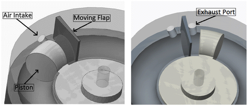
The concept engine can be split into four simple steps. Step one involves the external compression of air; then the air is injected into the combustion chamber along with the fuel as a pre-compressed non-premixed air-fuel mixture. Step two involves the ignition of the air-fuel mixture immediately after injection where the “top” of the combustion chamber takes the shape of a movable flap. Step three begins expansion where the pressure pushes the toroid section around until full expansion is reached. In step four when the toroid reaches the movable flap again, the flap opens into the gap inside the toroid and hot gas is exhausted out. When the toroid rotates to the initial position, the process occurs again. The size of the toroid gap was determined iteratively through code until the cylinder pressure was expanded down to near atmospheric pressure.
The concept engine utilizes Gasoline Direct Injection (GDI) to inject fuel into the combustion chamber. Zhao, Lai and Harrington (Citation1999) discusses the many benefits of using GDI over Port Fuel Injection (PFI), covering points in fuel system, combustion process, combustion chamber emissions and fuel economy. Switching to GDI showed an improvement in fuel economy upwards of 25%, which was found to be due to reduced pumping loss and higher compression ratio. GDI injection also showed to have a reduced cylinder to cylinder variation in air to fuel ratio due to the better control of fuel injection. Zhao also found that the mean droplet size of the atomized fuel was reduced to 16 microns with GDI compared to 120 microns when using PFI, improving air fuel mixing, evaporation, ignition and flame propagation.
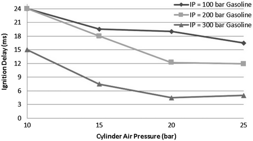
Figure shows the effect of in-cylinder pressure on ignition delay with cylinder pressures ranging from 10 to 25 bars. This figure shows how an increased cylinder pressure decreases ignition delay with an optimal pressure of 20 bars for an injection pressure between 200 and 300 bars. Also, Ghadikolaei observed that when the air pressure inside the cylinder increased, turbulence rose, which improved the air-fuel mixture (Ghadikolaei, Citation2014).
The advantage to the design of the concept rotary engine is its simplicity and large expansion volume. In traditional reciprocating IC engines, the rotor has to constantly change directions, losing energy by stopping piston momentum and reducing the efficiency of the system. The design discussed in this paper will be introduced in this section, explaining both the physical motion the engine undergoes and the thermodynamic process after each step. Then a review of the process of fuel injection and the effects that extended expansion has on combustion will be covered.
The design of the concept engine is illustrated in Figure (a) and (b), and Table . The initial advantage that can be seen is how thin the engine is. This allows for stacking multiple rotors together and increasing the overall power output while maintaining a small footprint and resulting in a high power-to-weight ratio. As shown in the following figures, the concept engine consists of a rotor, an oscillating flap, and a housing enclosure. The rotor takes the shape of a toroid section which rotates around a central axis; expanding and expelling the air-fuel mixture. When the flap moves to the “open” position as seen in Figure , pre-compressed air is injected into the combustion chamber along with fuel, which then gets ignited and combusts. After the rotor reaches full expansion and approaches the flap, the moving flap slides up and lays flush with the inside surface of the housing enclosure. Due to kinetic energy, the rotor continues its rotation and returns back to its initial position.
Table 1. Concept engine geometry
The major dimensions of the concept engine can be seen in Table . With an outside rotor diameter of just over twelve inches, the concept is engine very small, although the volumetric size of its cylinder is comparable to that of a traditional reciprocating IC engine. The table also displays the dimensions for the flap, which rests inside the housing enclosure.
Lastly, the position that was chosen for the spark plug ignition was determined using the KIVA-3 simulation program. For a test run, the ignition was placed at the top of the combustion chamber. This caused all the fuel to be burned, but increased emissions, and had a low thermal efficiency of around 10%. The ignition point was then moved from the center to 1 cm off center towards the fuel injection site in increments of 0.1 cm and kept at the top of the chamber. As the ignition point was moved outwards, increases in fuel efficiency were recorded, and the optimal point was found to be at 1 cm. Ignition timing was held constant. This modification brought up thermal efficiency to around 30%, lowered emissions by around 1,000%, but left a small amount of ~5% unburnt fuel within the chamber. With the ignition point found, injection angles into the chamber were varied between 90°, otherwise known as perpendicular to the chamber wall, and 45°. Best results were shown around 50°, indicating interaction with the top of the piston increased fuel turbulence and encouraged fuel atomization.
Like other rotary engine designs, the engine presented here is capable of much higher engine speeds than reciprocating engines as the high-stress conditions resulting from reciprocating actions are avoided. Engine loads are primarily limited the integrity of the flap required to produce the back-pressure to propel the piston. Structural integrity analysis and design limits for engine speed and loads are outside the scope of this work, which focusses on the thermodynamic performance of the engine concept.
2.2. Atkinson cycle
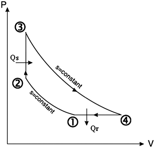
To easily analyze the thermodynamic process that describes the concept rotary engine, the Atkinson cycle was used. The Atkinson cycle was chosen, as it is thermodynamically identical to the operation of the concept engine with regard to the expansion of the working fluid to atmospheric pressure, whereas the Miller cycle generally expands the gases to a pressure above atmospheric conditions. Figure displays the changes in pressure and volume during each step in the traditional IC engine that was used as a guide for the concept engine. The PV diagram illustrates the isentropic compression, constant volume heat addition, isentropic expansion and constant volume heat rejection that an air fuel mixture experiences while within a combustion chamber.
The first step during the common Atkinson cycle involves the intake stroke. In the concept engine, the intake stroke consists of air moved into external compressor at one atmosphere; that will be called volume one (V1).
The second step of the cycle is where the isentropic compression takes place. In the common Atkinson cycle, compression is done by a cylinder inside the combustion chamber, but in the concept engine, air is compressed by an external compressor and injected into the chamber. This allows for not only a controllable compression ratio, but for more compression of the air when needed. As the pre-compressed air is injected into the chamber, fuel is injected at high velocity as well. Volume 2 (V2) is calculated as the ratio of V1 to the cylinders’ compression ratio.
The third step is the constant volume heat addition known as combustion. After the air and fuel are well mixed, a spark plug ignites the mixture and initiates combustion where the temperature inside the volume reaches its peak. This significant temperature increase in the chamber causes the pressure to increase for a short period as the piston continues to travel at a constant velocity.
After near full expansion is achieved, a valve is opened, and the hot gas is exhausted out of the engine. The rotor continues to rotate due to kinetic energy and returns to the position for pre-compressed air to be injected, repeating the above process again.
2.3. Combustion process
The oxidizer used in this project is stoichiometric air. For the hydrocarbon fuel used, the stoichiometric relation is expressed as Equation (1) (Turns, Citation2011). For this project, an octane rating of 87 was used. Increasing the octane level within the fuel corresponds with how well the fuel reacts to increasing compression ratios.(1)
(1)
This reaction was implemented in KIVA as a single-step global kinetic reaction mechanism. In total, 12 species were modelled, including the fuel, O2, N2, CO2, H2O, H, H2, O, N, OH, CO and NO. Aside from the kinetic fuel oxidation and Zeldovich model, all other species were modelled through six equilibrium reactions.
2.4. Oxides of nitrogen emissions
To analyze the levels of nitric oxide emissions that the concept engine may expel following combustion, the thermal Zeldovich mechanism was used. The Zeldovich mechanism consists of three chain reactions shown in Equations (2) through (4). These reactions represent the mechanism for producing active nitrogen from molecular nitrogen in the gas phase (Turns, Citation2011).(2)
(2)
(3)
(3)
(4)
(4)
The Zeldovich mechanism states that the rate of the forward reaction equals the rate of the reverse reaction. However, during the formation of NO, the reaction is no longer in equilibrium, and the forward reaction rates become much larger than that of the reverse rates (Peiyong & Wang, Citation2012). The Zeldovich model was solved within the chemical solver included in KIVA and was modelled through the respective kinetic reactions, where the pre-exponential factors are functions of temperature and species concentration, thus indirectly incorporating pressure effects other reaction rate (Amsden, O’Rourke, & Butler, Citation1989).
2.5. Fuel-air injection characteristics
One of the main contributing factors to the performance of an internal combustion system is the performance of the fuel injection system. The combustion process chosen for this study was the Atkinson’s cycle that has close to atmospheric pressure and temperature air injected into the compressor. This air is then compressed to anywhere from 15 to 20 atm at around 850 K depending on the compression ratio. Once the air is compressed, liquid fuel is injected by the fuel injectors into the chamber, which when exposed to the high pressure and temperature air, begins to atomize. The liquid fuel begins as small droplets roughly 10 to 100 μm in diameter and rapidly begins to either split up into smaller particles or evaporate as they penetrate into the chamber. Depending on the size of the combustion chamber and penetration of the fuel required, injection pressures can be anywhere from 10 to 50 MPa. Once one revolution passes, a spark ignition system ignited the air-fuel mixture creating a pressure which continues to move the cylinder around.
The main objective of this section is to determine the optimal fuel injection characteristics to maximize engine efficiency over a range of engine speeds. Simulations are done using both MATLAB and KIVA-3. Different injection hole sizes are analyzed along with a range of injection pressure, that when used with corresponding fluid properties of the air and fuel can determine injection angles, penetration and the atomization times of the fuel.
2.5.1. Injector characteristics
Fuel injector designs consist of an injector nozzle and a variable outlet valve such as a needle. Typically, the fuel injector builds up pressure upstream of the nozzle and after a barrier is passed the needle or ball valve shifts back and releases a specific quantity of fuel, then the nozzle closes and the process repeats. Some fuel injectors utilize a single hole nozzle while others have multiple holes. For the purposes of this study, a single-hole nozzle was studied.
2.5.2. Air injection
To achieve full combustion of the fuel, an appropriate mass of air must be injected into the combustion chamber. The compression ratio used in the MATLAB code took into account the volumes between the external compressor and the combustion chamber. The effects of varying compression ratios and injector dimensions were studied along with the fluid properties of ambient air over a range of pressures. Table shows various properties used in the code, such as compression ratio, chamber volume, and injector diameter.
Table 2. Combustion chamber and compressor specifications
The chosen injector geometry and injection fluid characteristics used for the simulation can be seen in Table . Again, the nozzle employed in the code was a single-orifice injector with a length/radius ratio of about 5.7, within the average range of 2–7.
Table 3. Injection characteristics
2.5.3. Fuel injection
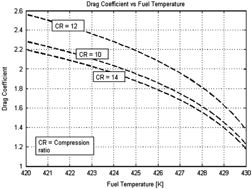
Figure shows the changing drag coefficient over different initial injection velocities ranging between 10 and 50 m/s. Each line represents a different initial velocity, and it can be seen that as injection velocity increases, the initial drag coefficient is reduced. There are two main contributors to the drag force; one is from the inertia of the fluid, and the other comes from the viscosity. As the velocity of injection increases, so does the Reynolds number. The increase in Reynolds number causes the contribution of the viscosity term in the Navier-Stokes equation to reduce. For moderate velocity droplets, the drag would increase, caused by unstable downstream vortices that separate from the body and shed downstream. As droplet velocities increase further, the passing flow breaks down into a turbulent wake, while still maintaining a laminar flow over the droplets’ boundary layer. The breaking down of the wake causes the wake to be narrower than during moderate flow and reducing drag (Borgnakke, Sonntag, & Van Wylen, Citation2009).
During fuel injection, droplets of fuel are dispersed into ambient air and quickly break up into smaller droplets, a process called atomization. In order for the fuel to quickly and evenly ignite during combustion, the fuel is required to break up into very small droplets as to increase the surface area across which liquid fuel may evaporate.
To simplify the evaporation model, several assumptions can be made:
| • | Negligible radiative heat transfer since most heat is transferred through conduction. | ||||
| • | Chamber wall interaction with the fuel injection is neglected. | ||||
| • | Average fluid properties such as temperature and pressure are assumed around the droplet bodies. | ||||
| • | No temperature gradient within the droplets. | ||||
To calculate the evaporation rate of the fuel droplet, it was necessary to consider the mass and energy conservation equations on the droplets. With some integration, the following evaporation rate for the fuel droplet was found, as a function of the surrounding air temperature.(5)
(5)
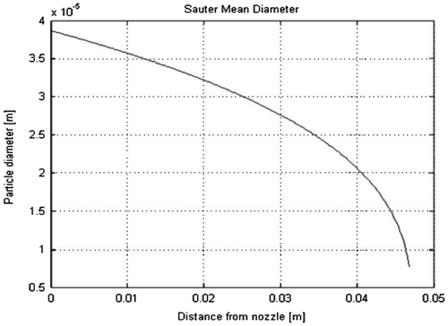
To find the average initial droplet size being injected, the Sauter Mean Diameter equation was used, Equation (6), along with results from Equation (5). Figure plots the average droplet size leaving the injector over the distance from the nozzle. Droplets are considered fully atomized at around 50 mm into the chamber.(6)
(6)
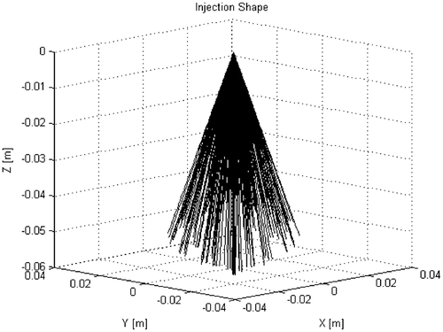
Finally, with the tabulated data on spray breakup, evaporation rates, and droplet instabilities, the fuel injection shape was made. Using the Monte Carlo method, droplets were injected individually into the combustion chamber at random directions within the pre-calculated cone angle. After a random angle for theta and phi where found, the initial droplet diameter was modified. As the droplet travels into the combustion chamber, the droplet loses mass due to evaporation, while the loss rate increases as the droplet reaches further into the chamber. The final injection cone can be seen in Figure . The injection shape is set at an angle of 30, and its penetration into the chamber reaches a distance of around 45 mm into the chamber, which means that the injection will not have direct interaction with the chamber wall, and run the risk of possible fuel-wall adhesion.
3. Results and discussion
3.1. Thermodynamic analysis simulation results
A MATLAB code was developed to include all the steps of the Atkinson cycle and the volumes used in the concept engine. In the code, the compression ratio was ranged from 8:1 to 20:1 to analyze the effect that initial pressure had on the combustion process. Modern vehicles typically run a compression ratio between 8:1 and 12:1, with high performance vehicles and race cars reaching compression ratios of 14:1. With a higher compression ratio, an engine is capable of extracting more energy from the injected air-fuel mixture, thus increasing the overall efficiency of the system. Along with the benefit of high compression ratios comes the risk of pre-igniting the fuel before the rotor has reached its intended position. Pre-ignition is more common among engines using low octane fuels, where octane is used to make a fuel more resistant to ignition in light of heat and pressure. Thus, one must be careful when choosing a high compression ratio as to avoid damage to the engine.
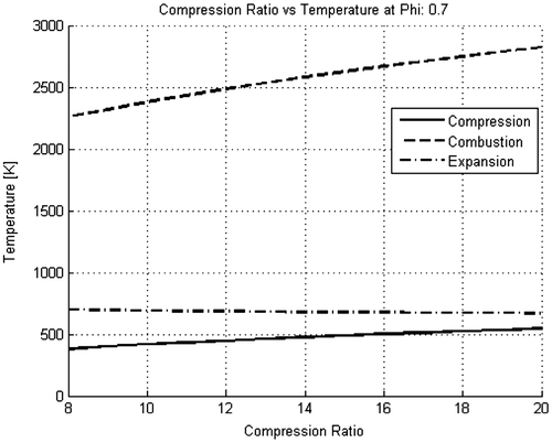
From the MATLAB simulation, the temperature and pressure changes during compression, combustion and expansion over different compression ratios were plotted, as can be seen in Figure . This figure was generated using variable specific heats, varying compression ratios, and the ideal gas law equations. It can be seen that combustion temperatures reach a mean temperature of 2,800 K, which is comparable to traditional reciprocating IC engines that usually run around 2,000–3,000 K (Patodi & Maheshwari, Citation2013). Plots for different equivalence ratios, Φ, were also studied, including 0.60, 0.65, 0.70 and 0.80. A Φ of 1 means that just enough oxidizer is present with the fuel for a complete combustion. Less than 1 means that the burn is lean, and greater than one represents a rich burn. Higher Φ’s can be seen to drastically increase the final temperatures of combustion and expansion. The increase in temperature can be attributed to increasing levels of fuel and energy potential in the combustion chamber. It is because this reason why only lean conditions were chosen.
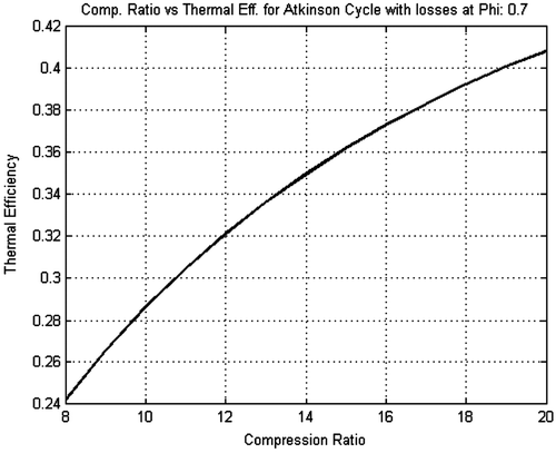
Figure plots the thermal efficiency over a changing compression ratio. A compression ratio of 14 proved to bring indicated thermal efficiency to be at 35. By increasing the expansion stroke, a further increase in thermal efficiency is observed. Furthermore, although it is ideal to increase thermal efficiency to its maximum, increasing the compression ratio can lead to pre-ignition as stated before and cause damage to the engine.
With the net work known, it is now necessary to find the total thermal efficiency in the system. By taking the differences in internal energy from the exhaust and combustion along with the efficiency over compression, one can find the total efficiency of the Atkinson cycle. For the purpose of this study, the compressor that was simulated had a power draw of 1,200 Watts with an efficiency of 76%, which was estimated by available compressor efficiencies in that power range. This simplified estimate is valid through the complete separation of the compression process from the combustion/expansion processes, which allows the separate compressor to run continuously at constant power to supply a intermediate storage volume.
Table displays the effects compression and Φ had on work output, horsepower, HP, and thermal efficiency, which shows that a higher compression ratio and Φ increase the overall performance of the concept engine. Thus, it would be ideal to use a strong external compressor to increase the power output of the engine, while using a relatively lean burn to avoid chances of pre-ignition and knock. The main problem that arises from using an external compressor is obviously the power necessary to run it. Air compressors pull anywhere from 10 amps to 20 amps, and if connected to a 120 V supply, will require upwards of 2,400 W of power.
Table 4. Values for work, HP and thermal efficiency for changing compression ratio and Φ
To accurately predict the mass flow rate of the injected fuel from the fuel injector, Equation (7) was used. If the upstream cylinder pressure is known along with the geometric dimensions of the fuel injector, the mass flow rate of fuel can be calculated. The flow through each nozzle is assumed to be quasi-steady, incompressible and one-dimensional. The flow rate of air through the air injector can be calculated using Equation (8). Equation (8) is used when flow velocities are at or exceed Mach, where the flow will be expected to choke.(7)
(7)
(8)
(8)
CD is the discharge coefficient, which is 0.4, An is the minimum nozzle area, ρf is the fuel density, and p is the pressure difference between the fuel injector and the cylinder.
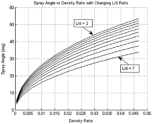
During fuel injection, the spray will usually form a cone-like shape as it exits the nozzle, also known as the atomization breakup regime (Leff, Citation1987). The angle the spray makes during injection can determine how effectively the fuel atomizes into the air. Equation (9) represents the spray angle the spray makes while in the atomization regime, and it can be seen that the angle is a function of the fuel’s liquid and gas density ratio and not the velocity in which the fuel is injected (Dent, Citation1971). Figure plots the range of injection angles over a changing density ratio, where it can be seen that with an increasing density ratio an increase in the injection angle occurs.(9)
(9)
g and l are the gas and liquid densities, and A is a constant for a specific nozzle size, which can be calculated with Equation (10).(10)
(10)
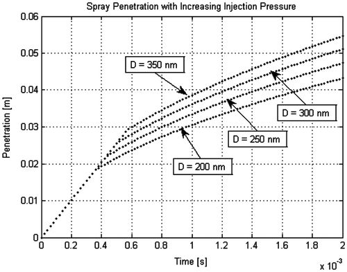
Based on Hiroyasu (Citation1985) Equations (11) and (12) are used to represent the spray penetration and the length of time for particle atomization. Figure plots the penetration range over an injector diameter from 200 to 350 nm. It can be seen that increasing the injector diameter causes a deeper spray penetration into the cylinder. The appropriate diameter can be chosen to best fit the size of engine as to limit the amount of fuel wall interaction.(11)
(11)
(12)
(12)
3.2. Combustion simulation results
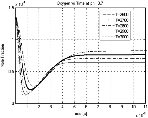
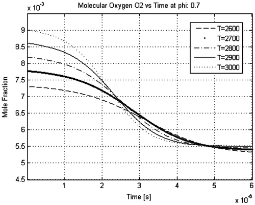
It is possible to assume that if the fuel is completely used up prior to the formation of NO, then the processes in the Zeldovich mechanism become uncoupled. When this occurs, N2, O2, O and OH concentrations are said to have reached their equilibrium values while N reaches steady state. Figure shows the lifetime of oxygen in the air-fuel mixture. One can see how combustion initially burns up most of the oxygen very quickly, before forming NOx and carbon dioxide. Looking at the lifetime of oxygen O2 in Figure , it can be seen how a combustion temperature of 3,000 K more rapidly burns the oxygen than at 2,500 K. Depending on the RPM of the concept engine, the speed at which the oxidizers get used up may be a factor, so controlling the amount of fuel and air entering the combustion chamber would benefit both fuel efficiency and combustion rates.
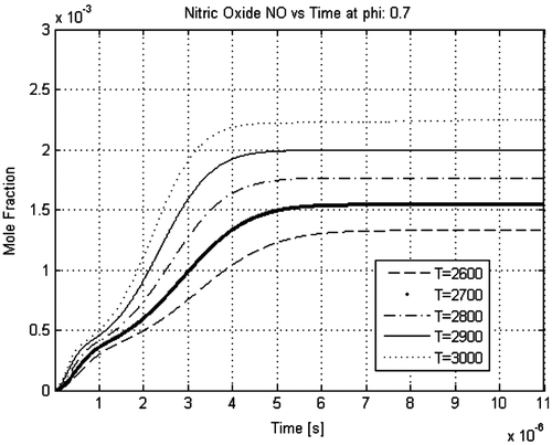
Finally, a plot for NOx emissions at different combustion temperatures is shown in Figure . It can be seen that higher combustion temperatures causes nitrogen and NOx outputs to increase, thus keeping a temperature at around 2,600–2,700 K would be better for the environment. Although the MATLAB simulation only took into consideration the fluid properties for combustion, further analysis in KIVA-3 determined how fuel mixing and fluid turbulence can prevent NOx formation.
3.3. CFD flow simulation of fuel and air injection mixing process
The injection and combustion phase was separated into two models for species transport, the injection phase without chemical reactions, and combustion phase with chemical reactions. The required transport equations for both gas and chemical species within the computational domain must be found. KIVA-3 offers several options for the calculation of the injected fuel and air and their physical properties as a gas mixture. To sufficiently study the effects of injection and combustion within the concept engine, several physical properties need to be understood, including: the mass, momentum, and energy of the injected droplets, fluid velocities and their trajectories, material transport to analyze the air fuel mixing and their chemical reactions. In order to calculate such data, three methods were used by KIVA-3, which are as follows:
| • | Discrete phase modeling or droplet tracking using both the momentum equation and a force balance for the individual droplets. | ||||
| • | Species transport or scalar transport. | ||||
| • | Multiphase flow modeling. | ||||
3.3.1. Mesh geometry
The actual geometry of the concept engine resembles a circular torus, with a piston cylinder section that fits inside and revolves around a central point. Due to the limitations within KIVA-3, a chamber in the shape of a straight cylinder that shared the same working dimensions as the toroidal cylinder proposed was used. The focus of this study is to analyze the expansion process within the combustion chamber, and because shape does not affect how gas expands, simplifying the chamber as a straight cylinder is admissible. After specifying the boundaries and the total dimensions of the chamber, the mesh could be generated using a program called K3PREP, whose parameters can be seen in Table . The mesh and submodel constants were calibrated using results from previous research done on more traditional IC engines using the KIVA-3 software (Micklow, Becknell, Tootoonchi, von Helldorff, & Levine, Citation2015).
Table 5. KIVA-3 input values
3.3.2. Combustion
An array of cases were set up for use in the KIVA-3 program, which iterated both the lengths of expansion after combustion and different sets of compression ratios. After all physical and thermal properties were imported, KIVA-3 was run, moving the cylinder from 0° top dead center to 180° bottom dead center with a variable step size of 0.0001 crank angle degrees. The program supplied emission data for residual fuel, oxides of nitrogen, carbon dioxide and carbon monoxide, to name a few.
3.3.3. Thermal analysis
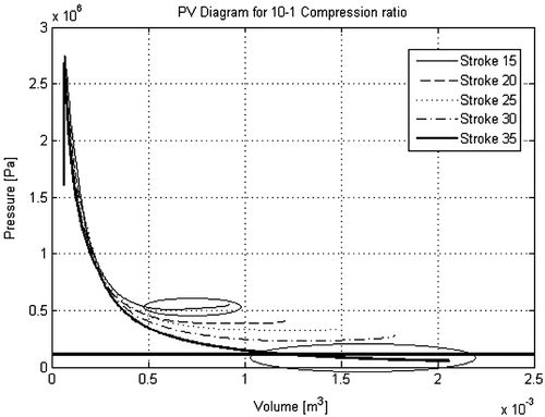
An analysis of final pressures was done to identify ideal levels of expansion so as to waste as little energy as possible during the expansion stroke. Simulations over strokes between 10 and 60 cm were analyzed, and it was concluded that a stroke of 10 cm and all strokes above 30 cm were inefficient. A stroke length below 15 cm was unable to expand the gas sufficiently to neither reduce emissions at exhaust nor extract reasonable energy from the highly pressurized gas, which at peak levels reached around 26 atm. All stroke lengths above 30 cm overly expanded the gas, causing internal pressures to reach well below 1 atm. Thermal efficiencies ranged from a low 11% at a 15 cm stroke to a high 58% at a stroke of 35 cm.
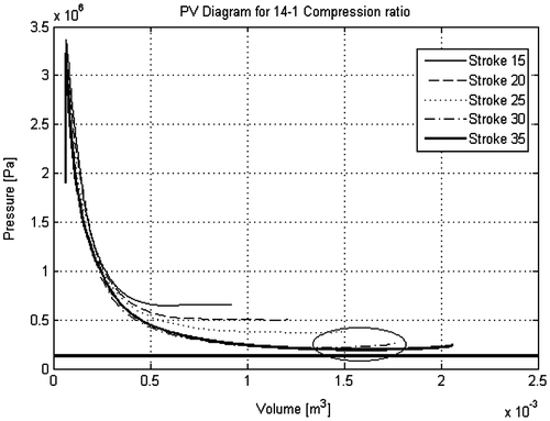
The peak pressure at combustion, and how far the pressure is reduced from the expansion process can be seen in Figures and . It can be seen that for an expansion stroke of 35 cm at a 10:1 compression ratio which has been circled, final pressure reduces past atmospheric pressure represented by the straight black line. However the final pressures slightly increase by increasing the compression ratio. Thus stroke lengths above 30 cm is not ideal. It can also be seen that increasing the compression ratio from 10:1 to 14:1 increases initial pressures by around 2 atm each, but final combustion pressures increase by around 5 atm.
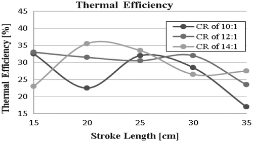
Finally, comparisons of the thermal efficiency under compressive losses can be done to gauge the level of effectiveness over each model, which can be seen in Figure . At a stroke length of 15 cm with a compression ratio between 10:1 and 12:1, indicated thermal efficiencies of 33% were recorded. Increasing the stroke length further resulted in drops in efficiency, and then an increase again when reaching a 25–30 cm stroke length. Increasing the compression ratio to 14:1, a low thermal efficiency is recorded at the 15 cm case, while increasing expansion to 20 and 25 cm results in an indicated thermal efficiency of between 33 and 35%. Increasing the stroke length further continued to drop the overall thermal efficiency, which was likely caused by reductions in the amount of fuel actually burned.
Figure 16. Thermal efficiency over increasing stroke length and compression ratio with compression losses.
3.3.3.1. Fuel atomization
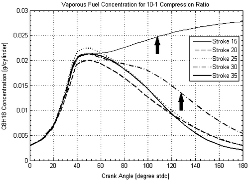
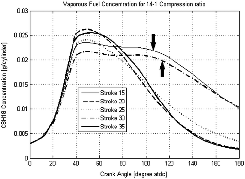
For the determination of the fuel consumption over the combustion and expansion process, a comparison of initial and final fuel levels was made. Data for the quantity of gaseous fuel was recorded over the entire expansion stroke. The fuel was injected into the combustion chamber, and immediately began to vaporize due to the high temperature gradient. During this vaporization, the quantity of gaseous fuel within the chamber increases and atomizes with the surrounding air. Figure displays the vaporous fuel concentration for a compression ratio of 10:1. With fuel injection beginning at 0 and lasting between 15 and 30 crank angle degrees, it can be seen that shortly after 40 crank angle degrees, the vaporous fuel begins to drop. This drop in concentration is a result of the rate of fuel combustion overtaking the rate of fuel atomization. After 40° of rotation, engines with stroke lengths between 15 and 30 cm begin to drop in overall concentration, reducing to around or just under initial levels, while a stroke length of 35 cm tends to shoot upwards in fuel concentration. As mentioned previously, all simulations were run under a 3,000 RPM load, meaning a stroke length of 15 cm would run slower than a stroke length of 35 cm. So through the 35 cm stroke test, it is apparent that the chamber expands much too quickly for the fuel to adequately burn and continues to propagate and atomize through the chamber, increasing concentrations. Typical flame speeds expected within an internal combustion engine are 16.5 m/s, whereas the velocity of the piston over a 35 cm stroke length running at 3,000 RPM is 17.5 m/s. This expansion velocity is faster than the flame speed, which causes the termination of the flame. This suggests that the engine speed for a prescribed length of the toroidal chamber is limited by the flame speed, as otherwise cooling effects from the gas expansion dominate and extinguish the flame.
During the 14:1 compression ratio analysis, which is shown in Figure , vaporous fuel concentration increased slightly and stroke lengths between 15 and 25 cm dropped back down below 5 mg/cylinder. The 30 cm stroke length had an 86% increase in final fuel concentration, while the 35 cm stroke length had a 55% drop in fuel concentration. Thus, including the pressure volume diagrams from Figure , it appears that a stroke length between 20 and 25 cm to be ideal for expansion.
3.3.3.2. Emissions
The fuel conversion within the internal combustion engine is modelled by a single-step global chemical kinetic mechanism that governs levels of pollutant formation at the end of every engine cycle. During combustion, the breakdown of molecules dominates, releasing energy in the form of heat, while the expansion process involves the oxidation of hydrocarbons and the formation of nitrogen oxides and other emissions due to the short residence time and chemical imbalance. All of these points are primarily governed by the method of compressing, igniting and expanding hot gases, but another main contributor to the formation of pollutants is the fuel. The amount of fuel injected into each cylinder is governed by the amount of air compressed into the chamber maintaining a stoichiometric ratio between air and fuel known to be 14.7 parts air and 1 part fuel. In practice, air to fuel ratios are kept at lean values, especially in GDI engines. While the local equivalence ratio may be high, the global equivalence ratio is significantly below stoichiometric conditions.
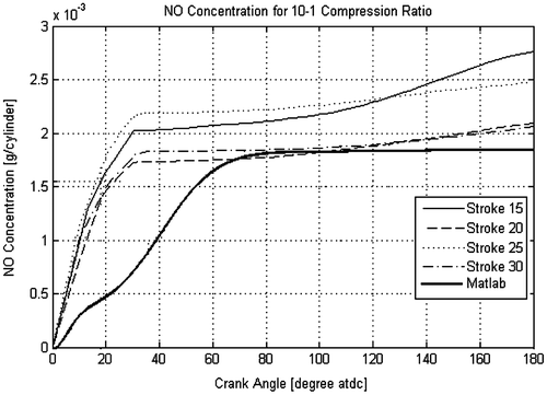
Figures and compare the results from both KIVA-3 and MATLAB. In Figure , it can be seen that the KIVA-3 model predicts immediate formation of NOx, reaching about 2 mg per cylinder after approximately 40 crank angle degrees, whereas the MATLAB model predicts a slower formation to just under 2 mg per cylinder, which does not peak until approximately 120 crank angle degrees before being fully expanded. The MATLAB model ran over a variable stroke length that was dictated upon necessary lengths of expansion. The model could be best compared to Stroke 25 and Stroke 30.
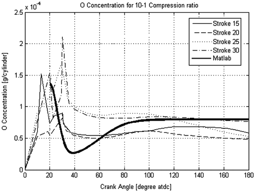
The second plot compares the rate at which oxygen is burned after ignition occurs. Fuel ignition in the KIVA-3 model initialized immediately after fuel injection, and oxygen levels at around 10 to 30 crank angle degrees show that combustion occurs then due to a decrease in oxygen levels. The MATLAB model begins at combustion, so comparisons to KIVA-3 started at 20 crank angle degrees. Similar to KIVA-3, oxygen was immediately burned and decreases from approximately 0.15 mg per cylinder to under 0.05 mg per cylinder. During the start of the cycle, air is injected into the chamber, where hot gases dissociate the molecular oxygen into a pair of atomic oxygen radicals, creating a peak concentration at 20 crank angles. Then combustion occurs and combines the atomic oxygen to molecular hydrogen to form water. Most of the cases visible show the concentration of oxygen to drop around 40° crank angle. It is here when the molecular oxygen combines with atomic hydrogen, forming hydrogen monoxide and atomic oxygen again, increasing its concentration for another 40 crank degrees. If pressures are high enough, the atomic hydrogen is consumed for a final time by water to form a pair of hydrogen monoxides dropping to its final concentration between 0.05 and 0.075 mg. Compared to the MATLAB model, a larger drop in initial oxygen, final oxygen levels increased back to levels comparable to KIVA-3 between 0.05 and 0.075 mg per cylinder.
Soot or particle formation through the combustion process was not considered for this work, as particle formation is primarily an issue for direct injected Diesel engines. This higher evaporation and combustion rates of Gasoline mitigate the formation of particle matter at significant levels.
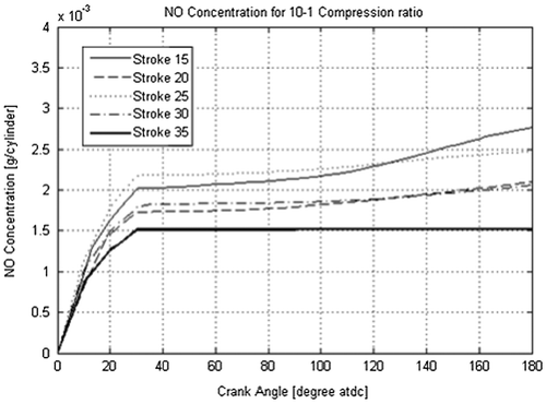
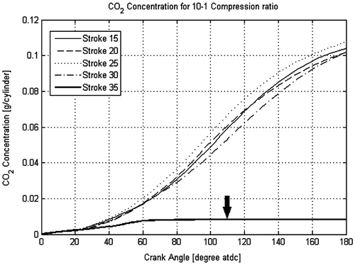
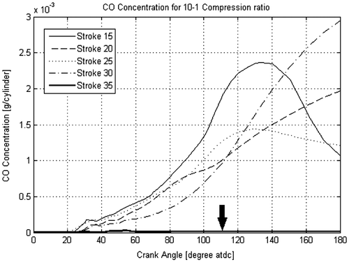
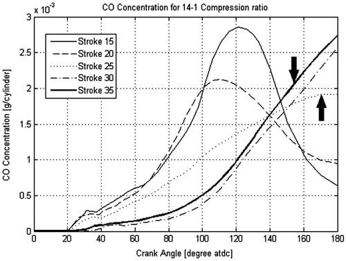
Concentrations for NOx, CO2, CO, OH, H2 and O formations were plotted as a function of crank angle. Figures through displays these emissions over stroke lengths from 15 to 35 cm at a 10:1 compression ratio. It can be seen in Figure that using a longer stroke length reduces overall NOx formations, which is likely due to the cylinder head having to move at a higher velocity and faster expansion resulting in reduced in-cylinder temperatures. As discussed in the previous section, a stroke length of 35 cm or higher decreases the overall consumption of injected fuel, which can be attributed to the over expansion of the hot gas and fuel leaving the existing flame front.
Carbon dioxide emissions can be seen on Figure . Here one can see how the concentration increases as full expansion is reached. Having CO2 in the exhaust typically means that hydrocarbons have been burned effectively, while having little CO2 would mean that much of the fuel had not been burned and cylinder velocities exceeded flame speeds. CO2 is made when the fuel dissociates and combines with molecular oxygen, forming carbon monoxide and molecular hydrogen. With enough time, the CO combines again with oxygen to form CO2, but if there is not enough time for the CO to form with the oxygen, or if there is not enough oxygen to combine with, CO2 will not form. Looking at Figure , one can see the inverse relationship to CO2 formation. Although the 35 cm case doesn’t seem to form CO due to the flame being extinguished by the expansion velocity. Reducing the stroke lengths to 15 cm through 25 cm, it’s apparent that fuel is being burned, since the concentrations for CO increase and drop back down before full expansion is reached.
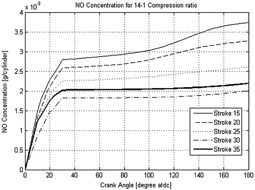
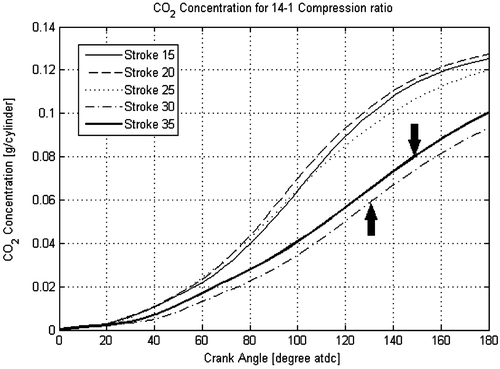
Then, Figures through give a summary of a compression ratio of 14:1. Again, it can be seen that increasing the compression ratio increased total NOx production and heat output, while decreasing CO production. CO2 maintains the same result as the previous two experiments with the exception of a 20 cm stroke, which had dropped approximately 20%.
4. Conclusion
This paper presents two mathematical models of a novel concept engine, implementing innovative designs which aim to increase thermal and fuel efficiencies compared to a traditional internal combustion engine. A comparative simulation of the fuel injection, combustion and expansion process is conducted to determine the effects of varying numerous engine parameters. Five concept engine configurations are compared, which were based on a modified rotary engine whose chamber was in the shape of a circular torus with varying piston lengths. A detailed study was conducted on varying the air to fuel ratios within the combustion chamber, along with fuel injection velocities and pressures to alter the injection shape. Since the influential parameter for combustion quality in any combustion engine is mixture quality, much attention was given to methods of injecting fuel and vaporization rates.
4.1. CFD simulation
The combustion simulations showed improvements in the thermal and fuel efficiencies, proving how extending the expansion process is necessary for effectively utilizing the injected fuel. The models that were tested ranged expansion from 15 cm to 35 cm and the results were closely analyzed. It was shown that stroke lengths below 20 cm and above 30 cm created undesirable results and keeping the stroke length between 20 and 30 cm was ideal. Generated pressure volume diagrams illustrated that increasing the stroke length above 30 cm resulted in overexpansion for low compression ratios below 12:1. It was also shown that increasing the stroke length to 35 cm or higher would results in cylinder velocities much too high for the fuel to adequately atomize into the air and be effectively burned. It was thus shown that the piston speed for the concept engine, as a function of chamber dimensions and engine speed, is limited by the flame speed. Although the emission plots shown in section display the stroke length of 35 cm to release the lowest toxic emissions to the atmosphere, it was due to the fact that most of the injected fuel was not being burned. While NOx emissions were shown to be significantly reduced through proper dimensioning of the combustion/expansion volume, the results suggest that catalytic exhaust after-treatment is still required for compliance with strict modern emissions regulations.
From these plots it was concluded that using a stroke length of 20–25 cm added to the initial 1 cm chamber height under a compression ratio above 10:1 produces the most efficient combustion while expanding the gas sufficiently enough to extract the most energy. The fuel efficiencies for these two models range between 32 and 35%, which is an increase over the average fuel efficiency of 14–30%.
Funding
The authors received no direct funding for this research.
Additional information
Notes on contributors
Matthew James Jensen
Denis Allemant Andre graduated with his Master’s of Science in Mechanical Engineering from Florida Institute of Technology (FIT), under the advisement of Dr Matthew Jensen. The research presented in this paper is one of many research activities related to automotive engineering and design as part of the automotive engineering focus area at FIT. Automotive research at FIT is primarily focused on simulations using advanced computational tools, ranging from combustion and powertrain modeling to autonomous systems and intelligent vehicle control systems. The goal of automotive research at FIT is to improve vehicle efficiency and safety through industry relevant projects, while training new engineers to succeed in the automotive industry.
References
- Amsden, A., O’Rourke, P., & Butler, T. (1989). KIVA II: A computer program for chemically reactive flows and sprays. Los Alamos National Labs, LA-11560-MS.
- Borgnakke, C., Sonntag, R. E., & Van Wylen, G. J. (2009). Fundamentals of thermodynamics. Hoboken, NJ: Wiley.
- Chen, L., Lin, J., & Wu, C. (1998). Efficiency of an Atkinson engine at maximum power density. Energy Conversion and Management, 39(3–4), 337–341.10.1016/S0196-8904(96)00195-1
- Dent, J. C. A. (1971). A basis for the comparison of various experimental methods for studying spray penetration (p. 4). AE Technical Paper 710571.
- Ganesan, V. (2012). Internal combustion engines (4th ed.). Pennsylvania Plaza, NY: McGraw Hill.
- Ghadikolaei, M. A. (2014). Effect of cylinder air pressure and fuel injection pressure on combustion characteristics of direct injection (DI) diesel engine fueled with diesel and gasoline. International Journal of Application or Innovation in Engineering & Management (IJAIEM), 3(1), 1–8.
- Hiroyasu, H. (1985). Diesel engine combustion and its modeling. In Proceedings from the 1st International Symposium on Diagnostics and Modeling of Combustion in Internal Combustion Engines (COMDIA 1985). Sept 4–6, 1985, Tokyo, Japan, 53–75.
- Leff, H. S. (1987). Thermal efficiency at maximum work output: New results for old heat engines. American Journal of Physics, 55(7), 602.10.1119/1.15071
- Martins, J., Pereira, C., & Brito, F. (2016). A new rotary valve for 2-stroke engines enabling over-expansion. SAE Technical Paper 2016-01-1054, 2016.
- Martins, J., Uzuneanu, K., Ribeiro, B., & Jasasky, O. (2004). Thermodynamic analysis of an over-expanded engine. SAE Technical Paper 2004-01-0617, 1, 1–1.
- Micklow, G. J., Becknell, D., Tootoonchi, E., von Helldorff, H., & Levine, D. (2015). The effect of local fuel/air ratio on the performance and pollutant emission formation of direct injection compression ignition engine configurations. International Journal of Modern Studies in Mechanical Engineering, 1(1).
- Patodi, K., & Maheshwari, G. (2013). Performance analysis of an Atkinson cycle with variable specific heats of the working fluid under maximum efficient power conditions. International Journal of Low- Carbon Technologies, 8(4), 289–294.10.1093/ijlct/cts055
- Peiyong, N., & Wang, X. (2012). Modeling the formation of NOx and soot emissions in a diesel engine at different humidity. International Journal of Green Energy, 9(8), 815–828.
- Sady, T., Jazayerib, S. A., Fathia, M., & Jahanian, O. (2016). Miller cycle application to improve lean burn gas engine performance. Energy, 109, 190–200.
- Sakita, M. (2006). A cat-and-mouse type rotary engine: Engine design and performance evaluation. In Proceedings of the Institution of Mechanical Engineers.
- Turns, S. R. (2011). An introduction to combustion: Concepts and applications. Boston: McGraw-Hill.
- Zhao, J. (2017). Research and application of over-expansion cycle (Atkinson and Miller) engines—A review. Applied Energy, 185(1), 300–319.10.1016/j.apenergy.2016.10.063
- Zhao, F., Lai, M., & Harrington, D. (1999). Automotive spark-ignited direct-injection gasoline engines. Progress in Energy and Combustion Science, 25, 437–562.10.1016/S0360-1285(99)00004-0

