
 ?Mathematical formulae have been encoded as MathML and are displayed in this HTML version using MathJax in order to improve their display. Uncheck the box to turn MathJax off. This feature requires Javascript. Click on a formula to zoom.
Abstract
This paper presents a solution to plan a path using a new form of the Bees Algorithm for a 2-Wheeled Differential Drive mobile robot. This robot is used in an indoor environment. The environment consists of static and dynamic obstacles which are represented by a continuous configuration space as an occupancy map-based. The proposed method is run in two respective stages. Firstly, the optimal path is obtained in the static environment using either the basic form or the new form of the Bees Algorithm. The initial population in the new form of the Bees Algorithm consists only of feasible paths. Secondly, this optimal path is updated online to avoid collision with dynamic obstacles. A modified form of the local search is used to avoid collision with dynamic obstacles and to maintain optimality of sub-paths. A set of benchmark maps were used to simulate and evaluate the proposed algorithm. The results obtained were compared with those of the other algorithms for different sets of continuous maps. This comparison shows the superiority of the new form of the Bees Algorithm in solving this type of the problems. The proposed method was also tested using AmigoBot robot. In this experiment, the proposed method was implemented using multi-threading techniques to guarantee real time performance at the dynamic stage. The results of this experiment prove the efficiency of the proposed method in a real time.
Public Interest Statement
The popularity of using robots as alternatives to human beings in the real world is becoming more common nowadays, especially in industry, medicine, entertainment and military. These robots need means to think and to mimic the natural behavior of people. In this paper, an artificial intelligence method is proposed to give robots thinking ability to find their way in buildings. The method presented is based on the Bees Algorithm which simulates foraging behavior of real honey bees. The proposed method is implemented as a computer program designed to find the shortest path in a building. This path is planned in a way to avoid collision with stationary barriers and moving objects such as other robots.
1. Introduction
Applications of autonomous Wheeled Mobile Robots (WMR) increased dramatically in several fields because of their simple structure and fast motion in different environments and terrains (Kuss-Hana & Joukhadar, Citation2015). Generally, an autonomous WMR system consists of three main sub-units: localization, mapping and path planning (Siegwart & Nourbakhsh, Citation2004). Research in the field of path planning begun in 1960s for all robot types (Raja & Pugazhenthi, Citation2012). Whereas, Mobile Robot Path Planning can be defined as the process of finding an obstacle-free path between a predefined start and goal points in an environment (Siegwart & Nourbakhsh, Citation2004). Robot environments are either static or dynamic. In case of a static environment, the positions of obstacles are stationary whereas changing chronologically in case of the dynamic environment. These two cases could be existing in indoor or outdoor environments. Indoor path planning implies that map of the environment is known while the environment in the case of outdoor path planning is unknown. The aim of using path planning algorithms is to convert high-level specifications of tasks, that humans perform into low-level specifications (LaValle, Citation2006). This is done by finding an optimal path and giving it to the robot as a track or a sequence of points to follow it as motion commands. When the environment contains dynamic obstacles, the path planning algorithm should not only find the optimal path but also keep tracking of it. Therefore, the algorithm should interact with the present positions of obstacles, predict future paths and update its path in a real time at a high enough frequency in order to remain reactive to its surroundings events.
Usually, there are multiple allowed paths for a wheeled mobile robot to follow. The definition of an optimal path is based on criteria such as path length, time consuming and energy. Assuming that the shortest distance is the criterion of the performance under specific constraints then the path planning problem becomes an optimization problem (Raja & Pugazhenthi, Citation2012). WMR Path planning has been solved in several algorithms, these algorithms are classified into classical and intelligent algorithms. Rapidly-Exploring Random Trees (RRT) (LaValle, Citation1999), Artificial Potential Field (APF) (Khatib, Citation1986), Real-Time R* and Partitioned Learning Real-time A* (El-Khaili, Citation2014) are used for solving dynamic path planning problem as classical approaches. However, when the size of the search space becomes large then these approaches suffer from an insufficiency in performance and trapping in local optima because of the NP-hard complete nature of the problem. Therefore, intelligent optimization algorithms have been used in solving path planning problems such as, Genetic Algorithm (GA) (Arora, Gigras, & Arora, Citation2014; Zhang, Zhao, Deng, & Guo, Citation2016), Particle Swarm Optimization (PSO) (Islam, Muftee, & Mahfuzul Hossain, Citation2014), Simulated Annealing (SA) (Miao, Citation2006), Ant Colony Optimization (ACO) (Gigras & Gupta, Citation2014) and Bacterial Foraging Approach (BFA) (Abbas & Ali, Citation2016). Although, these algorithms solved the problems of path planning, discretization and pre-processing of environment maps are needed as an essential step to run those kind of methods. Discretization and pre-processing decreases the accuracy and leads to non-optimal paths.
In this paper, a new form of the Bees Algorithm (BA) -which is a population-based search algorithm- is proposed to solve path planning problem of mobile robots. The proposed method will handle the map of the environment as its reality without discretization or pre-processing. A basic form of the Bees Algorithm (BA) was originally proposed by Pham and his colleagues to solve continuous optimization problems (Pham et al., Citation2006). BA is characterized by its simplicity, low computational cost, the ability to solve different types of problems and the ease of adoption of the algorithm to suit problems (Kashkash, Haj Darwish, & Joukhadar, Citation2017). In brief, the aim of this paper is to prove that: the Bees Algorithm is able to find an optimal path for a wheeled mobile robot in a known dynamic environment.
The optimal path will be found in two stages. Firstly, the optimal path will be initiated by taking into account static obstacles only. Then, the optimal path obtained will be given to the robot to follow it. As the robot moves in the dynamic environment, the proposed method will update the path online to maintain an optimal free-collision path.
The remaining sections of the paper are as follows: Section 2 discusses the configuration space, Section 3 describes the Bees Algorithm, Section 4 presents the proposed method, Section 5 shows the experimental results and the comparisons, the real experiment is discussed in Section 6, and finally, Section 7 gives the conclusion.
2. Configuration space
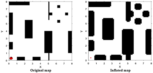
The configuration space is a set of allowed movements of the robot in the environment (Siegwart & Nourbakhsh, Citation2004). The position of a wheeled mobile robot is represented by . In the 2D configuration space, it is possible to represent the robot as a point. However, the surrounding area of obstacles should be increased proportionally to the geometric shape of the studied robot as shown in Figure . In order to keep tracking of dynamic environment the time should be added to the robot representation, then the position of a wheeled mobile robot is given as:
.
Figure 1. Configuration space.
The configuration space of the obstacles C
obs is a part of C-space that is occupied by the obstacles and the robot will collide with and cannot move in. The free configuration space C
free is a part where the robot can move in without collision. C
free can be calculated using Equation (Equation1(1)
(1) ):
(1)
(1)
In the proposed method, the configuration space of the environment is represented by occupancy map-based structure. This structure represents the environment by continuous data as the Cartesian coordinate. It uses a discriminative model which returns the probability of obstacle existent in the given coordinate (Francis, Ott, & Ramos, Citation2017). Equation (Equation2(2)
(2) ) clarifies this model:
(2)
(2)
All points of the map will be used to find the optimal path in comparable with a grid-based structure and other technique. The lower left corner is the start coordinate of the map and the start point and the destination point can exist at any position inside the map.
3. The Bees Algorithm
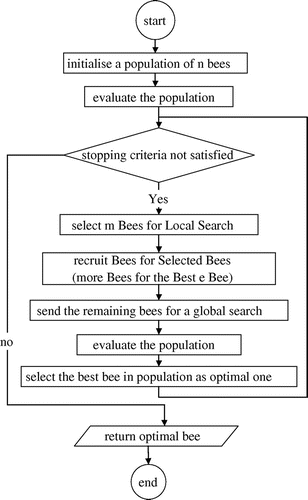
The Bees Algorithm (BA) is a population-based algorithm, this algorithm simulates the behaviour of honey bees to solve complex problems (Pham & Castellani, Citation2015). The BA obtains the nearest solution to the best one in an optimization problem (Marzi, Haj Darwish, & Helfawi, Citation2016). It is a robust algorithm with low computational cost. Data with real values are handled directly by the Bees Algorithm without binary encoding (Haj Darwish, Citation2009). It is used to work with continuous and complex data (Kashkash et al., Citation2017). The BA performs two types of search, local and global search. Local search accelerates the convergence to the optimal solution by recruiting more worker bees to potential patches to exploit them. Whereas, global search maintains the diversity among solutions and explores new promised patches which have not been explored yet (Hussein, Sahran, Siti, & Sheikh Abdullah, Citation2016).
The Bees Algorithm needs to pre-set a number of parameters:
| • | (n) number of the scout bees (initial population size). | ||||
| • | (m) number of the bees selected as a good of (n) bees. | ||||
| • | (e) number of the elite bees which are selected as the best bees from (m). | ||||
| • | (nep) number of the recruited bees for each bee in the (e) bee. | ||||
| • | (nsp) number of the recruited bees for each bee in the (m–e) bee. | ||||
| • | (ngh) initial size of neighbourhood patch. | ||||
| • | stop condition. | ||||
Figure shows the flowchart of the Bees Algorithm.
Figure 2. Flowchart of the Bees Algorithm.
4. Proposed algorithm
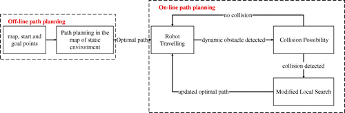
The proposed method performs path planning process in a dynamic indoor environment which contains dynamic and static obstacles. The algorithm consists of two stages. In the first stage, robot path planning is applied off-line to find optimal path in the environment with only static obstacles. While in the second stage, the obtained path is given to the robot to follow it. At the same time, the algorithm updates the path on-line to avoid collision with any new obstacle and to guarantee the optimality of sub-paths. This optimality of the path is maintained using the modified form of local search. Figure illustrates this process.
Figure 3. Proposed schema for path planning.
4.1. Static stage
4.1.1. The feasible solution
The feasible solution is the path which satisfies the following conditions:
| • | Basic path points does not fall in an obstacle area. | ||||
| • | There is no intersection between the path and any obstacle in the environment. | ||||
If the set of the basic path points is given by the following:
(3)
(3)
then the feasible path should comply with the following:(4)
(4)
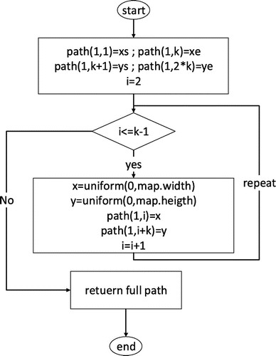
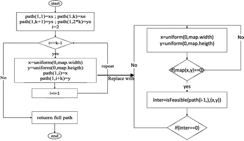
4.1.2. Generation of the initial population
The initial population consists of n bees which are generated randomly. Each bee represents a path and consists of k points. However, the start and the destination points are identified previously thus k−2 points should be created. Generation of a new point is performed randomly by producing x and y coordinates in the range [0, width (map)] and [0, height (map)] respectively by using uniform distribution function. Formula (5) illustrates this process:
(5)
(5)
Then the start and the destination points are added to form the complete path. Figure shows the flowchart of generation of the initial population process. Each bee in the initial population represents a complete path which is modelled as the following form:(6)
(6)
Figure 4. Generation of the initial population function.
where
| • | (x s , y s ) is the coordinate of the start point. | ||||
| • | (x d , y d ) is the coordinate of the destination point. | ||||
| • | length is the value of the evaluation function for the path. | ||||
4.1.3. Modified method to initiate population
In case of the complex environments, only and only if feasible paths are accepted in the new population. This procedure speeds up the process to reach an optimal solution. This is done by adding the start point to the path firstly, after that, producing a new point as it was mentioned in Section 4.1.2. This new point should satisfy the following criteria:
| • | The new point does not fall in an obstacle. | ||||
| • | There is no intersection between new path segment and an obstacle. | ||||
These steps are repeated till generating k−2 points. Then, the destination point is added if the whole derived path is feasible else the derived path is ignored. Figure clarifies the new method to create a new population. With this modification, the optimal path is reached by a fewer number of evaluation function calls. This modification is essential in case of complex configuration spaces.
Figure 5. Modified method to initiate population.
4.1.4. Evaluation function
Evaluation function of a bee in the population is an accumulative sum of the Euclidian distances between each two successive points in the basic path. Weight for each point located in an obstacle, and weight
for each sub-path that intersects with any obstacle are also used in this evaluation function. The mathematic form of the evaluation function is represented by Equation (7).
(7)
(7)
where P is a number of points that fall in obstacles and I is the sum of the lengths of line segments that intersect with the obstacles.
The goal of the proposed method is to search for the shortest path between the start and destination points. So, and
are added to maximize the value of evaluation function as a penalty when an intersection with an obstacle occurs. Therefore, the evaluation of the bee with bad path is assigned to a big value, so this bee will be ignored in the next iterations.
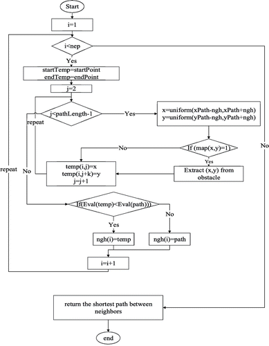
4.1.5. Local search
The individuals of the population are ordered ascending based on the path lengths which were pre-calculated. Good bees / m / are selected from the population and the elite / e / among them are distinguished. To run local search, / nep / and / nsp / bees are recruited for the elite bees / e / and the remaining good bees / m–e / subsequently. However, / nep / is greater than / nsp /. Local search is performed by producing a new point in the neighbourhood of each point of the basic path points except start and destination ones. The uniform distribution function is used to produce coordinates of the new point in the range [x−ngh, x + ngh] and [y-ngh, y + ngh]. The coordinates of the new point are as the following equations:
(8)
(8)
Blue rectangles in Figure illustrates the neighbourhood of each point.
Figure 6. Local search process.
If the new point falls in an obstacle, it will be translated from that obstacle. Hence, the evaluation for the new path is evaluated. The new path is saved, if its length is smaller than the length of the general path, which is called for it, or it will be ignored. Figure clarifies the local search process.
Figure 7. Flow chart of local search.
4.1.6. The global search
Global search is performed in respect of searching for new solutions, the remaining bees (n−m) are sent randomly to find new random paths.
The values of the evaluation function for these bees are calculated at the end of this stage. Then all bees in the new population are ordered ascending based on the evaluation function value. The best path (bee) is selected as the first bee in the population, it is thus, the shortest path. These steps will be repeated until the evaluation value of the optimal solution does not change. At that time, the Bees Algorithm (BA) returns the optimal path.
4.2. Dynamic stage
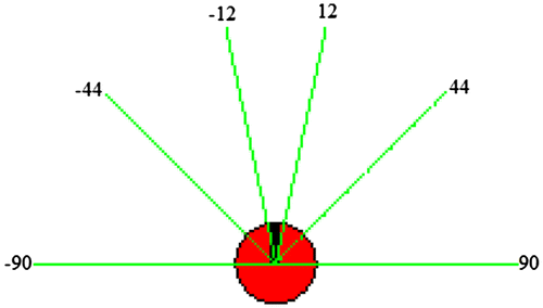
The proposed method finds the optimal path in the static environment. This path is given to the robot to follow it in the dynamic environment. The robot follows the path with a scanning process using the surrounded sensors. The robot has eight on-board sensors which give the robot ability to cover an area with 360 view. Six sensors are located at the front-end of the robot. The sensors are distributed in the following angles as shown in Figure :
Figure 8. Sensors distribution.
The proposed method begins to read the measurements of the sensors and detects the new obstacles which may be a dynamic or static. New obstacle is detected when a new obstacle enters to the coverage area of the robot sensor and satisfies distance conditions in addition. All information about movement, velocity and position of the robot and the obstacles in the environment are known. This information are used to analyse the possibility of collision between the robot and the obstacle. The robot keeps following the original path in the case of no collision will occur as Figure illustrates. However, in the case of collision as shown in Figure , the proposed method call the local search of the Bees Algorithm again for the part of the path which contains imminent collision point. The new obtained sub-path should be the shortest one. The original path is updated so the robot can follow the new free-collision path.
Figure 9. There is no collision.

Figure 10. There is collision.
4.2.1. Proposed method for obstacle detection
The obstacle detection is the process of informing the robot for new obstacles in the given environment. The proposed method allows the detection of the new obstacles simultaneously with the robot motion toward the goal. This implementation includes the following steps.
The measurements of sensors are acquired. Then the distance between the obstacle and robot is calculated from the centre of the robot to the nearby surface of the obstacle.
The existing of an obstacle is determined based on the following: If the second and third sensors, the third and fourth sensors or the fourth and fifth sensors have detected new obstacle, and the distance between the obstacle and the robot centre is greater than a threshold. When an obstacle is detected, the collision possibility method is called to determine whether the robot and obstacle will collide.
4.2.2. Collision possibility
Not all detected obstacles will collide with the robot, even they are in the sensors range of the robot. The possibility of the collision occurrence is determined based on position and orientation angle of the robot and the detected obstacle. The time and the position of the collision is calculated as follows.
If the current position of the robot is P r1(x r1, y r1) and it is moving toward P r2(x r2, y r2), and if the current position of the obstacle is P o1(x o1, y o1) and its target is P o2(x o2, y o2). The equations of the robot movement are given by (9).
(9)
(9)
The equation of the obstacle movement is given by (10).
(10)
(10)
The robot and the obstacle will collide when:
(11)
(11)
and are greater than 0 (exactly positive). Then the position of the intersection can be calculated by substitution of Equation (9) in Equation (10).
4.2.3. Modified local search
The sub-path of the robot, in case of collision (Figure (a)), consists of three points. First point is the robot current location, second one P(x, y) is the imminent collision point and third one
is the next point in the robot path as shown in Figure (b). This sub-path will contain the obstacle in the case of collision. So, modified local search is proposed, here, to find an alternative collision-free sub-path. The modified local search is called when both of the following conditions are valid. First condition, when a new obstacle enters the coverage area of robot sensor. Second one, when a decision of collision possibility is positive. When an imminent collision is detected, an obstacle is added virtually to the map at the imminent collision point as illustrated in Figure (c). Then, the area of all obstacles should be increased as it was mentioned in Section 2. In this local search, a bee represents the sub-path and the value of its evaluation function. This bee is modelled as a following string:
(12)
(12)
Figure 11. Modified local search.
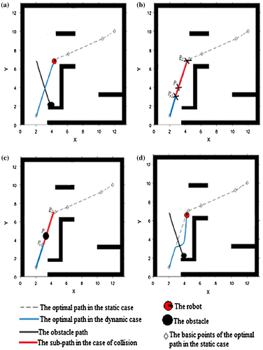
The size of the neighborhood, for this local search, is initialized with a value proportional to the area of the detected obstacle. The recruited bees are called to find a collision-free sub-path. The local search is implemented by generating a new point randomly using uniform distribution function in the neighborhood of the collision point using Equation (8).
The recruitment of the bees is repeated to find an optimal free-collision sub-path. Neighbourhood shrinking technique is used to guarantee the optimality of the derived sub-path. The modified local search returns the optimal sub-path when its length does not change. This new sub-path is given to the robot to follow it as shown in Figure (d).
The computational cost of the proposed local search is low because of two reasons. First one, only a single new point is generated in the neighborhood of the imminent collision point P in the sub-path for each recruited bee. Second reason, uniform distribution function is used to generate the coordinates of this new point and its computational cost is low (Stuart & Norvig, Citation2009). Therefore, the modified local search does not have an effect on the time performance of the proposed algorithm.
4.3. Neighbourhood shrinking
Firstly, the size of neighbourhood is initialized with a large value. This value is a percentage of the size of a map. If the length of the optimal path does not change after a number of iterations, then the size of the neighbourhood is decreased as follows:(13)
(13)
Initialization of the neighbourhood with a large value accelerates the discovery process in the configuration space. The neighbourhood shrinking invests the local search process around the current point. This process guarantees the evolution of the solution.
5. Experimental results and comparisons
Matlab R2015a with robotics toolbox is used for implementing the proposed method. Platform of maps, which are ranged between simple and complex, are used to run experiments in both the static and dynamic stages. Anyway, the obstacles are inflated by additional area. The proposed method is always implemented in two stages. In the first stage, off-line path planning is run without moving obstacles and handled as a static environment. So, this implementation does not have an effect on the robot performance in the real time. In the second stage, obtained optimal path is given to the robot for following and, at the same time, path planning is run on-line to avoid collision with moving obstacles and to guarantee the optimality of the sub-path in the dynamic environment. This stage should be implemented in the real time to ensure that robot responses to commands in the correct timing.
5.1. Static environment
The experiment is implemented on a benchmark of different static maps. These maps range in the complexity of the configuration space.
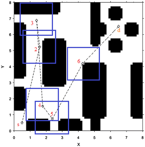
If the environment is given in Figure (a), the first step is to inflate the environment with additional obstacle area as it is illustrated in Figure (b). The additional area is shown in Figure (c). Figure (d) shows the optimal path with length 13.9.
Figure 12. Summary of the implementation of the proposed method in static case.
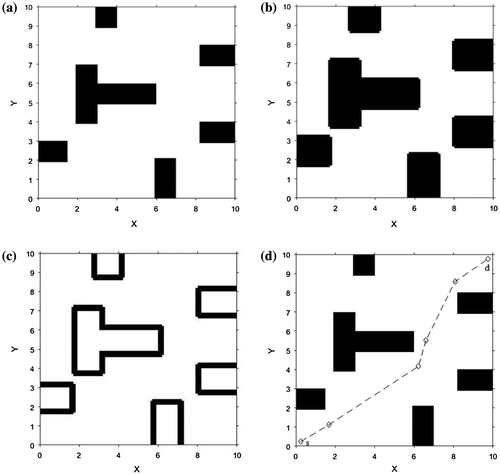
Figure compares the evolution of the solution in two proposed methods to reach the optimal solution in the mentioned environment. As shown, the modified Bees Algorithm is faster than the traditional Bees Algorithm.
Figure 13. Evolution of the solution.
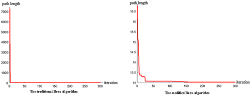
Table shows the result of applying the proposed method to 4 different maps which are shown in Figure . The experiment shows the optimal path which was found using traditional Bees Algorithm for maps in Figures (a)–(c). However, a complex environment as in Figure (d) needs the modified Bees Algorithm to create the initial population.
Table 1. The static environment
Figure 14. Static environment.
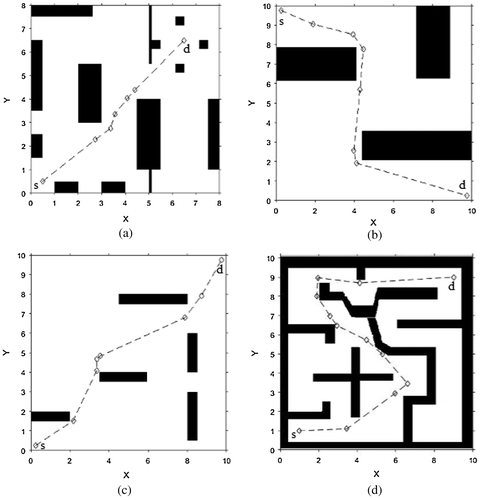
Table shows also the results of the Probabilistic Road Map (PRM) (Kavraki, Svestka, Latombe, & Overmars, Citation1996) which is a classic approach in the static environments only. The probability of failure of the mention approach is given in the Table . Figure illustrates some of the failure cases for the PRM method
Figure 15. Failure examples of the PRM.
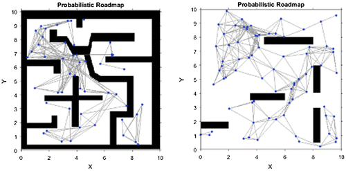
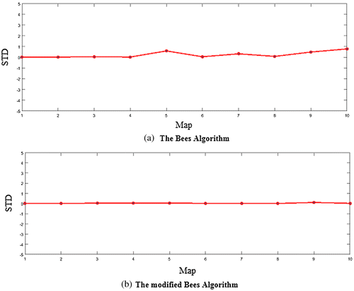
Table presents the mean length of the obtained paths for a set of 10 maps which they and their results are showed in Figure (Maps 4, 6, 7, 8 and 9 of Figure are available at http://rkala.in/codes.html). These maps are considered as a benchmark. The implementation of proposed methods is repeated 20 times for each map to validate the stability and robustness of the proposed methods. Figure shows the standard deviation for both algorithms. From Figure , it is obvious that the standard deviations of the proposed methods are small. However, the standard deviation of the modified Bees Algorithm is still smaller than that of the traditional Bees Algorithm.
Table 2. The mean and the standard deviation
Figure 16. The set of studied map.
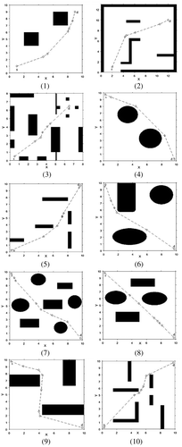
Figure 17. Standard deviation of the results.
5.2. Dynamic environments experiment
5.2.1. Case study 1
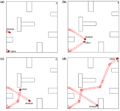
The map of the environment and the optimal path in the static case with total length 14.62 are shown in Figure .
Figure 18. Case study 1 results.
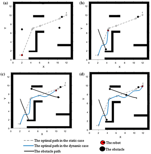
This path is given to the robot to follow it in the dynamic environment which consists of general environment with 2 new moving obstacles and a new static one as shown in Figure (a). The first obstacle starts to move simultaneously with the robot and the motion of both is updated as it is illustrated in Figure (b). Figure (c) shows the avoidance process of the second obstacle. The third new obstacle has a fixed position. Figure (d) shows the full final path with length 16.3.
5.2.2. Case study 2
More complex environment is shown in Figure (a) with an optimal path obtained in the static stage with the length 23.08. Figure (b) shows the full final path in the dynamic stage which its length is 23.84 (Maps of Figure (d) and Figure are available at http://imr.ciirc.cvut.cz/planning/maps.xml).
Figure 19. Case study 2 results.
5.2.3. Case study 3
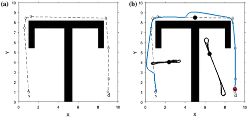
Figure shows the experimental results on two maps, their results were compared with the result of the Genetic Algorithm in (Zhang et al., Citation2016), Tuncer and Yildirim (Citation2012) and Karami and Hasanzadeh (Citation2015) as shown in Table .
Figure 20. Case study 3 results.
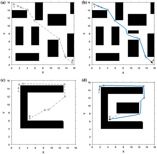
Table 3. Comparision between the proposed method and GA
6. Real experiment using AmigoBot
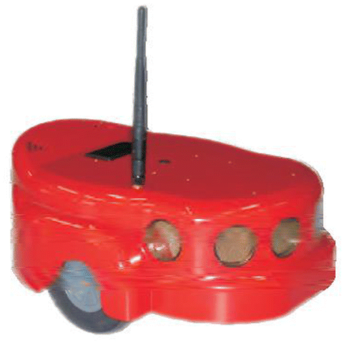
Besides, an experiment is executed on a real wheeled mobile robot in Robotics lab. It is AmigoBot manufactured by MobileRobots. AmigoBot has two differential wheels and a castor wheel for balancing, as in Figure . Dimensions of the robot are (28 × 33 × 13) centimeters. AmigoBot has eight ultrasonic sensors distributed in the following angles to give complete coverage for the robot:
Figure 21. Amigobot robot.
The first six sensors are, only, used in the experiment. The sonar ranging acquisition rate is set to 25 Hertz (40 ms per transducer). Sensitivity ranges from 10 cm to 5 m (Team AmigoBotTM Operations Manual, Citation2005).
C++ with ARIA libraries are used to implement the proposed method on the mentioned robot using Microsoft Visual Studio. The proposed algorithms are programmed using C++. ARIA (Advanced Robotics Interface for Applications) libraries provides an interface to the platform of Amigobot. The maps of environments are created using Maper3Basic. MobileSim is used for Simulation.
The proposed algorithm is implemented using a multi-threading program to guarantee the response in real time. One thread is used to lead the robot motion to follow the optimal path which obtained from the static stage, another thread is used to monitor the sensors value and analyse collision possibility, and another thread is used for obstacle motion. In case of detecting collision with a nearby obstacle, the task of the first thread is interrupted and the robot path is updated to complete its motion to the destination point. Those programs were run on a personal computer with CORE I3 processor, 4 GByte ram and Windows 7 operating system. This computer is connected with Amigobot using TCP/IP protocol to send commands and receive sensors readings.
The robot moves with 750 millimetre/second as a max transitional speed and 300°/second as a max rotational speed. The sensor range of the robot is set to 1500 millimetres to guarantee a safe distance between the robot and imminent collision region. The modified local search was executed 100 times to find the average execution time. The average time is 6 ms. Amigobot command processor runs interrupt cycle every 1 ms to get any new command for robot motion. While the robot moves by its thread, another thread detects new collisions. When a new collision is found by the second thread, the modified local search is called and the original path is updated. When the processor of robot is interrupted to get new command, the new motion command will be executed for a new sub-path. So, the robot will be aware of new modifications in the real time.
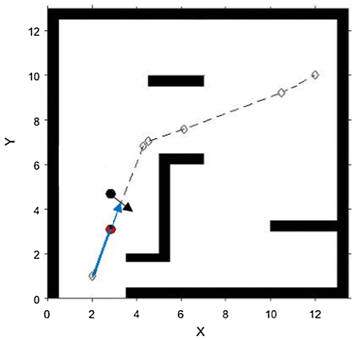
Figure (a) shows the optimal path obtained in the static environment with length 13.9. However, in Figure (b) there is an imminent collision with the new obstacle. So, the path is updated and its new length is 14.11. The update process is done in real time.
Figure 22. Collision avoiding of static obstacle.
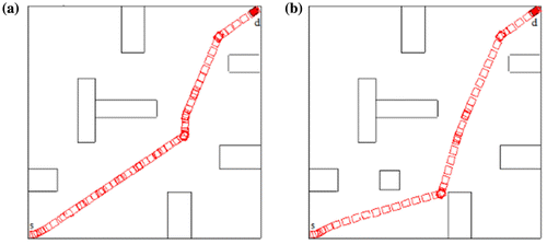
In Figure (a), the main robot and another one move in the same environment. The second robot is an obstacle for the first one. So, it should be avoided. Figure (b) shows the start of the motion for both robots. Figure (c) illustrates the process of update path. Finally, the full optimal path with length 14.8 is shown in Figure (d).
Figure 23. Collision avoiding of moving obstacle.
The results of this experiment are adequate proofs that the proposed algorithm is executed in the real time. So, the robot can move and respond to the proposed algorithm in the real time.
7. Conclusion
In this paper, the Bees Algorithm has been applied to find an optimal path in indoor environments. The environment contains both static and dynamic obstacles. The optimal path is obtained in the static environment using either the basic Bees Algorithm or the modified Bees Algorithm. The robot is capable of following the obtained path and avoiding new obstacles. Detection of an obstacle depends on the range of robot sensors and the analysis of the collision possibility. If the collision possibility method shows the existence of the collision with a new obstacle, this collision will be avoided using the modified local search of the Bees Algorithm. Neighbourhood shrinking is applied to improve the performance of the algorithm in the local search stage. The new form of the Bees Algorithm succeeds in solving the path planning problem in high complexity configuration spaces. The results of the experiments show the robustness of the proposed method in solving this type of the problems. The results of the proposed algorithm were compared with those of other algorithms in both off-line and on-line stages. The simulation illustrates that the obtained path was shorter, smoother and more direct. Real time performance is guaranteed by using multi-threading system to run the proposed algorithm at the dynamic stage. The result of time discussion shows that the robot responds to a new update at the correct time. An experiment on a real robot called AmigoBot was performed to validate the proposed method. Results of the Real experiment shows the strength of the proposed method in planning an optimal path in a real time.
Funding
The authors received no direct funding for this research.
Additional information
Notes on contributors
Ahmed Haj Darwish
Ahmed Haj Darwish was born in 1976. He received his PhD degree from Cardiff University, UK in 2009. Currently, he is an associate professor at the Department of Artificial Intelligence and Natural Languages, Faculty of Informatics Engineering, University of Aleppo, Syria. His research interests include Robotics, Intelligent Optimization Techniques, Fuzzy and Neural Systems and Image Processing, as well as their applications.
Abdulkader Joukhadar
Abdulkader Joukhadar was born in 1968. He received his PhD degree from Aberdeen University, UK in 2004. Currently, he is an associate professor at the Department of Mechatronics Engineering, Faculty of Electrical and Electronic Engineering, University of Aleppo. The central theme of his research is in the field of Robotics, Robot Control, Probabilistic Robotics and Intelligent Control Systems.
Mariam Kashkash
Mariam Kashkash was born in 1991. She received BEng of Informatics Engineering from University of Aleppo, Syria in 2013. She is a master student at the Department of Artificial Intelligence and Natural Languages, Faculty of Informatics Engineering, University of Aleppo, Syria. Her interested areas are Robotics and Intelligent Optimization Algorithms.
Related Research Data
References
- Abbas, N. H. , & Ali, F. M. (2016). Path planning of an autonomous mobile robot using enhanced bacterial foraging optimization algorithm. Al-Khwarizmi Engineering Journal , 12 (3), 26–35.
- Arora, T. , Gigras, Y. , & Arora, V. (2014). Robotic path planning using genetic algorithm in dynamic environment. International Journal of Computer Applications , 89 (11), 9–12.
- El-Khaili, M. (2014). Path planning in a dynamic environment by the approach of the sliding on edge. International Journal of Advanced Computer Science and Applications , 5 (8), 86–92.
- Francis, G. , Ott, L. , & Ramos, F. (2017). Stochastic functional gradient for motion planning in continuous occupancy maps. In IEEE International Conference on Robotics and Automation (ICRA) .
- Gigras, Y. , & Gupta, K. (2014). Metaheuristic algorithm for robotic path planning. International Journal of Computer Applications , 85 (3), 26–29.10.5120/14822-3056
- Haj Darwish, A. (2009). Enhanced Bees Algorithm with fuzzy logic and Kalman filtering . Cardiff: Cardiff University.
- Hussein, W. , Sahran, S. , Siti, N. , & Sheikh Abdullah, H. (2016). The variants of the Bees Algorithm (BA): A survey. An International Science and Engineering Journal , 47 (1), 76–121.
- Islam, R. , Muftee, H. , & Mahfuzul Hossain, S. (2014). Autonomous robot path planning using particle swarm optimization in dynamic environment with mobile obstacles & multiple target. In International conference on mechanical, industrial and energy engineering (pp. 1–6). Khulna.
- Karami, A. , & Hasanzadeh, M. (2015). An adaptive genetic algorithm for robot motion planning in 2D complex environments. Computers and Electrical Engineering , 43 , 317–329.10.1016/j.compeleceng.2014.12.014
- Kashkash, M. , Haj Darwish, A. , & Joukhadar, A. (2017). Solving maze problem using newly modified Tremaux’s Algorithm with the Bees Algorithm. In the 3rd international conference on Electrical and Electronic engineering, Telecommunication engineering and Mechatronics (pp. 182–186). Beirut: IEEE.
- Kavraki, L. E. , Svestka, P. , Latombe, J.-C. , & Overmars, M. H. (1996). Probabilistic roadmaps for path planning in high-dimensional configuration spaces. IEEE Transactions on Robotics and Automation , 12 (4), 566–580. doi:10.1109/70.508439
- Khatib, O. (1986). Real-time obstacle avoidance for manipulators and mobile robots. The International Journal of Robotics Research , 5 (1), 90–98.10.1177/027836498600500106
- Kuss-Hana, D. , & Joukhadar, A. (2015). A novel control-navigation system-based adaptive optimal controller & EKF localization of DDMR. International Journal of Advanced Research in Artificial Intelligence , 4 (25), 29–37.
- LaValle, S. M. (1999). Rapidly-exploring random trees: A new tool for path planning .
- LaValle, S. M. (2006). Planning algorithms (1st ed.). Cambridge: Cambridge University Press. Retrieved from http://planning.cs.uiuc.edu/ 10.1017/CBO9780511546877
- Marzi, H. , Haj Darwish, A. , & Helfawi, H. (2016). Training ANFIS using the enhanced Bees Algorithm and least squares estimation. Intelligent Automation & Soft Computing , 23 (2), 227–234.
- Miao, H. (2006). Robot path planning in dynamic environments using a simulated annealing based approach . Brisbane: Queensland University of Technology.
- Pham, D. T. , & Castellani, M. (2015). A comparative study of the Bees Algorithm as a tool for function optimization. Cognet Engineering , 1–28.
- Pham, D. T. , Ghanbarzadeh, A. , Koç, E. , Otri, S. , Rahim, S. , & Zaidi, M. (2006). The Bees Algorithm – A novel tool for complex optimisation problems . London: Manufacturing Engineering Centre.10.1016/B978-008045157-2/50081-X
- Raja, P. , & Pugazhenthi, S. (2012). Optimal path planning of mobile robots: A review. International Journal of Physical Sciences , 7 (9), 1314–1320.
- Siegwart, R. , & Nourbakhsh, I. (2004). Introduction to autonomous mobile robots (1st ed.). London: MIT Press.
- Stuart, R. , & Norvig, P. (2009). Artificial intelligence: A modern approach (3rd ed.). New Jersy: Prentice Hall.
- Team AmigoBotTM Operations Manual . (2005). (1st ed.).
- Tuncer, A. , & Yildirim, M. (2012). Dynamic path planning of mobile robots with improved genetic algorithm. Computers & Electrical Engineering , 38 (6), 1564–1572.10.1016/j.compeleceng.2012.06.016
- Zhang, X. , Zhao, Y. , Deng, N. , & Guo, K. (2016). Dynamic path planning algorithm for a mobile robot based on visible space and an improved genetic algorithm. International Journal of Advanced Robotic Systems , 1 , 1–17.