 ?Mathematical formulae have been encoded as MathML and are displayed in this HTML version using MathJax in order to improve their display. Uncheck the box to turn MathJax off. This feature requires Javascript. Click on a formula to zoom.
Abstract
The deregulated electric power industry creates a scope for the private companies to enter and compete in different activities of electric power system market. The electricity transmission and the determination of wheeling cost are more challenging in the deregulated power environment. Flexible Alternating Current Transmission System (FACTS) controllers are used for solving various transmission system problems for the maximum benefit. This paper proposes a power flow tracing methodology incorporating the contribution of each generating unit towards load demands and line flows, for the computation of both generation cost and wheeling cost. Also the rating and location of different types of FACTS devices for the minimization of line losses for the shrinkage of both generation cost and wheeling cost, and an optimal unit commitment algorithm for further reduction of both costs are proposed. Case study is taken for the standard IEEE 30-bus system, for verifying the effectiveness of the proposed algorithm.
Public Interest Statement
For over hundred years, the electric power supply industry worldwide operated as a regulated industry with only one company or state owned agency that generated, transmitted, distributed and sold electric power and associated services in any area. Since the mid-1980s, the environment of the power industry started changing rapidly from the regulated conventional setup to a deregulated one, to provide electricity at a low tariff, efficient planning of the expansion of the existing capacity, cost minimization, more choice to customers and service at its best. In the deregulation environment, generation, transmission and distribution of electricity are independent activities, and private companies can enter and compete in these activities. Private power producers bear generation cost for power production and wheeling cost for power transmission cum distribution of electricity. Optimal location of suitable custom power devices to benefit the private power producers financially from the aforementioned costs is proposed in this paper.
1. Introduction
The electric power industry involves the generation, transmission, distribution and utilization of electricity; however the mounting cost-effective essentials and security concerns had headed to the regulation of it. In the regulated electric power industry, the power generation, transmission and distribution activities are single-entity operated. The storage of electricity in large magnitude for future usage, balance of power supply and radically growing load demand and maintenance of uninterrupted power supply can’t be achieved economically. To achieve this along with more efficient power production cum power delivery at low cost with the usage of the existing facilities, the generation, transmission and distribution of electricity need to be talented at minimum cost but at maximum efficiency. In several countries, the electric power industry has been deregulated or restructured with the power generation, transmission and distribution activities handled by different entities. The benefits from the deregulation include low tariff, effective capacity extension preparation, more choice for customers and superior amenity (Sood, Padhy, & Gupta, Citation2002).
In 1990s, Indian government made numerous transformations and allowed the private sector to join in the power generation sector. The revision of the Indian Electricity (IE) act in the year 2003 brought about the split-up of the vertically assimilated state electricity boards into GENeration COrporation (GENCO) for power generation, TRANSmission COrporation (TRANSCO) for power transmission and DIStribution COMpany (DISCOM) for power distribution. Consequently, a no. of Independent Power Producers (IPPs) entered into the restructured power market (McGovern & Hicks, Citation2004). IPPs do not own the Transmission and Distribution (T & D) network and hence have no power of renowned territory. IPPs, therefore, make use of the TRANSCO network for “wheeling” the electricity.
Wheeling encompasses the transmission of electricity from its seller to its buyer through the third-party owned T & D network. Wheeling seriously shakes the network losses, re-dispatch of generating units, T & D network line flow constraints and retrieval of embedded capital costs. The seller pays the wheeling cost to the wheeling company for power transfer as well as for meeting additional losses. Transmission pricing evaluation structure need to be concise, transparent and effortlessly implementable, such that it offers same opportunity and more options to all users, encourages the proficient usage of the wheeling company for additional investment, and recovers the capital investment, running cost and reinforcement cost of the wheeling company (Xu, Dong, & Wong, Citation2006). Transmission pricing analysis involves the determination of wheeling viability and transmission service cost. Need of widespread data and broad usage of tools in both mathematical approach and complex analytics have made the transmission cost computation and its allocation among various wheeling customers more complex (Sedaghati, Citation2006). Generally the wheeling company resolves the wheeling cost based on the plant capital cost, plant load factor etc.; however both market and political deliberations could also influence the transmission pricing.
Karthikeyan, Jacob Raglend, and Kothari (Citation2013) compared the power plants generated powers using nodal must-run share index technique in the absence of and in the presence of Thyristor Controlled Series Compensator (TCSC) and Thyristor Controlled Phase Angle Regulator (TCPAR) under steady state condition of the power system. Ghahremani and Kamwa (Citation2013) presented a genetic algorithm based graphical user interface to find the optimal locations and sizing parameters of multi-type FACTS devices to maximize the static loadability in large power systems. NguyAen, Nguyen, and Karimishad (Citation2011) proposed an Optimal Power Flow (OPF) formula based on Newton’s algorithm augmented with the set of stability inequality constraints for economic dispatch together with nodal price calculations and to optimize the reference inputs to the FACTS devices for enhancing system stability and decreasing nodal prices. Ardakani and Blumsack (Citation2016) proposed a sensitivity-based technique to calculate the marginal market value to put forward the efficient FACTS devices impedance adjustments to provide the right financial incentives to the FACTS devices owners to optimally operate their assets in competitive power markets. Rahimzadeh and Bina (Citation2011) formulated an optimization problem and defined a new objective function to manage the transmission congestion, and presented an index based objective function to determine the optimal number of STATic synchronous COMpensator (STATCOM) and Static Synchronous Series Compensator (SSSC) for the economic improvement of electricity power market. Rahimzadeh, Tavakoli, and Viki (Citation2010) proposed a novel method based on genetic algorithm to find the location, the operating point as well as the number of multi-type FACTS devices, STATCOM and SSSC in steady-state situation of medium and large-scale systems, using average-neural lossy model, in the restructured environments for effective reduction of nodal prices. Singh, Singh, and Srivastava (Citation2007) suggested a new reactive power spot price index to determine the optimal location of Static Var Compensator (SVC) in the power system with the objective of minimization of the real and reactive power spot prices, generation cost, system real power loss, total wheeling charges, and enhancement of the system loading margin during normal as well as critical contingency cases. Bruno, Carne, and Scala (Citation2016) presented the opportunity for dynamic control of transmission lines impedance through TCSC during hasty disturbances and new protection schemes for both voltage maintenance and transient stability maintenance. Sakr, El-Sehiemy, and Azmy (Citation2016) presented an adaptive Differential Evolution (DE) algorithm to allocate perfectly the optimal no., siting and sizing of TCSC for reducing power losses, improving voltage profile and reducing installation cost during normal and emergency operating conditions. Chang (Citation2014) proposed the performance index sensitivity factor technique to determine the optimal location for TCSC and fitness sharing multi-objective particle swarm optimization method to maximize the system loadability and minimize TCSC installation cost. Tiwari and Sood (Citation2013) proposed an investment cost recovery based efficient and reliable optimization approach to fix the optimal location and rating of TCSC in double-auction power market to maximize the social welfare and minimize the device investment cost. Verma and Gupta (Citation2006) formulated a nonlinear optimization problem to compute the nodal spot prices for both real and reactive powers using OPF solutions to maximize the social welfare in the open power market using a Unified Power Flow Controller (UPFC). Kamarposhti and Lesani (Citation2011) compared static voltage stability margin enhancement in power systems in the presence of STATCOM, TCSC, SSSC and UPFC on maximum loading point, applying saddle node bifurcation theory.
From the literature review, it can be concluded that optimally the no., rating, placement or combination of any of these of suitable FACTS device(s) is considered in most of the recent articles for the technical progress of the power system or for the economic benefit to the owners of different entities of the electricity power market. The main objective behind the power system technical progress in a few recent articles is found to be transmission congestion management to maximize the system loadability, network loss reduction, static voltage stability margin enhancement, transient stability maintenance etc. In some research articles, the power system entities’ owners like electric power producers and FACTS device owners are benefited through the shrinkage of generation cost, device investment cost, device installation cost etc. This paper proposes a modified power flow tracing methodology incorporating the computation of contribution of each generating unit towards different types of loads and different types of line flows, while computing generation cost and wheeling cost. Also the optimal placement of suitable FACTS device is proposed with an aim to reduce the network losses to the most extent so as to improve the technical performance of the power system effectively as well as to financially benefit the electric power producers to the utmost degree by lessening their generation cost and wheeling cost simultaneously. And an optimal unit commitment algorithm for further reduction of the aforementioned costs is proposed. Case study has been conducted in IEEE 30-bus system to authenticate the efficacy of the endorsed algorithm.
2. Power flow tracing methodologies
Either single entity or more entities involve in the wheeling process. However, in the latter case, the contribution of each generator in supplying a particular load, line flow or line loss is required to compute the individual wheeling costs of generators. The power flow tracing methods figure the usage of different transmission network elements by different generators and loads (Cvijić & Ilić, Citation2014). The two topological, proportional sharing principle based tracing methodologies are simultaneous equations approach based Bialek’s tracing method and graph theoretic approach based Kirschen’s tracing method. The load flow solution is the pre-requisite for these two tracing methods (Rao et al., Citation2010).
Bialek’s tracing technique proposes the upstream looking algorithm to allocate the wheeling charge among generators and losses among loads, and downstream looking algorithm to allocate the losses among generators and wheeling charge among loads, with both algorithms grounded on the computation of topological distribution factors (Su, Liaw, & Li, Citation2006). Bialek’s upstream looking algorithm used in this paper is as follows:
Of a transmission network with “m” branches and “n” nodes, if “B” represents an (m × n) sized “incidence matrix” with its each element value equal to unity during active power flow from “m” bus to “n” bus, negative unity during active power flow from “n” bus to “m” bus and zero during no active power flow between “m” and “n” buses, and “F” represents an (m × 1) sized vector of branch active power flows, then Equation (1) sets up an (n × n) sized matrix with its (i, j) element representing active power flow from bus-i to bus-j.(1)
(1)
where “B d ” and “B u ” are two (m × n) sized matrices, both derived from “B”, with “B d ” and “B u ” consisting of 1’s and -1’s respectively, with the value of other elements in both matrices equal to zero.
An (n × n) sized non-singular matrix can be had using Equation (2).(2)
(2)
where I and P are (n × 1) sized vectors of nodal active power flows and ones respectively.
kth generating unit’s contribution of real power to ith bus real power load and jth line’s real line power flow can be estimated using Equations (3) and (4) respectively.(3)
(3)
(4)
(4)
where P G and P D are (n × 1) sized vectors of nodal active power generations and nodal active power demands.
This scheme can handle either DC or AC power flows and hence can be practiced even to fix the generating units contributions of reactive power demands and reactive line power flows using Equations (5) and (6) respectively.(5)
(5)
(6)
(6)
3. Transmission pricing methodologies
The capital cost, running cost and reinforcement cost of a wheeling company constitute its transmission cost. Transmission pricing needs to please the network owners with the recovery of transmission cost and network customers with satisfaction towards the network usage (Unsihuay & Saavedra, Citation2006).
Different electricity markets in different countries implemented different transmission pricing schemes during the last few years. In all the schemes executed, the transmission cost is allocated among various wheeling customers on various bases. More precisely, the wheeling cost computation schemes translate the transmission cost into transmission charges (Leite Da Silva, De Carvalho Costa, & Monteiro Mattar, Citation2006).
Different transmission transaction cost computation paradigms are classified as incremental or marginal cost paradigms and embedded cost paradigms. The incremental wheeling cost computation paradigms involve the allocation of the existing transmission system costs among the utilities’ intuitive customers and new transmission costs among the new users of the transmission network. For the technical analysis of the cost based transmission pricing, the difference among transmission prices and transmission costs becomes very problematic and puzzling in the incremental transmission pricing methodologies. Also these methodologies do not recover the investment cost and hence the embedded cost paradigms dominate the incremental cost paradigms in all these aspects. In the embedded cost paradigms, the sum of all existing and new costs of the transmission system is allocated among various transmission network users, according to their extent of use of the transmission system (Orfanos, Georgilakis, & Hatziagyriou, Citation2013). Embedded wheeling cost computation methodologies include postage stamp methodology, contract path methodology, boundary flow methodology and two line-by-line methodologies namely distance based line-by-line methodology and power flow based one. All these methodologies are found to be fair to all wheeling company customers and good source of satisfactory remuneration to the transmission system owners. The postage stamp methodology assumes that the entire transmission network is used in the wheeling transaction irrespective of the actual transmission facilities that carry out the transaction. As a consequence, the recovery of embedded capital costs would be limited to the entire transmission facilities of the wheeling company. The contract path methodology depends on charging the transacting utilities between two points, based on a specific, pre-defined, continuous path. A share of the asset costs plus the cost of new investment along the contract path is allocated to the wheeling customers in proportion to their use, using a postage-stamp rate, which is determined either individually for each of the transmission systems or on the average for the entire grid. Boundary flow methodology calculates the charges for transmission transactions across the borders of a grid and independent of distance being wheeled, thereby giving incorrect economic signals. Under line-by-line methodology, the transmission system capital cost is allocated proportionally to the line flow changes caused by transmission transaction, based on the maximum transacted power magnitude and distance between the points of entry and exit of transacted power in the network. Computing the product of line power flow and line length of each transmission line, the line-by-line methodology reasonably reflects the actual usage of transmission systems and guarantees the full recovery of fixed transmission costs, thereby allocating the transmission system cost among various network users for each transaction. The distance based line-by-line methodology considers the geographical distance and the power flow based one considers the electrical distance between the seller and the buyer of electricity. This embedded wheeling cost methodology is transparent, intuitively logical, conceptually straightforward, correct economic signal provider, and impartial to the order of wheeling transactions. In this paper, the power flow based line-by-line wheeling cost computation methodology is analyzed for transmission pricing determination.
A long transmission line has more weightage than a shorter one during transmitting the same amount of power. Likewise transmission lines with different materials, thermal ratings and costs, will have different weightages for the same length. Moreover, the cost of FACTS devices can’t be retained by considering only line lengths. Inclusion of guesses in such circumstances leads to sacrifice the accuracy of the power flow based line-by-line methodology. It can be avoided by including a predetermined weighting factor replicating the average revenue requirement per unit capacity of each line.
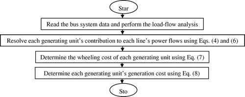
Equation (7) can be used to determine the transaction-wise wheeling cost, which is given by(7)
(7)
where WC t represents the wheeling cost for transaction t in Rs./MVA, S j,t represents the MVA flow in line j due to transaction t, L j represents the length of line j in km, C j represents the pre-determined unit cost reflecting the cost per unit capacity of line in Rs./MVA-km and i represents the total no. of transmission lines.
In case of multiple wheeling transactions, this paradigm delivers right economic signs irrespective of the distance of entities involved in the wheeling process, without providing any priority order (Nojeng, Hassan, Said, Abdullah, & Hussin, Citation2014). ith generating unit’s generation cost can be estimated using Equation (8).(8)
(8)
where a i , b i and c i are ith generating unit’s fuel cost coefficients in Rs., Rs. per MW and Rs. per MW2 respectively.
Figure shows the flowchart for MW.km scheme for wheeling cost determination.
4. Optimal power dispatch
Unit Commitment (UC) involves the optimization of generating units to encounter the power demand at least generation cost in the regulated power industry (Saravanan, Das, Sikri, & Kothari, Citation2013). While acquiring the UC schedule, Price Based UC (PBUC) involves the minimization of generation cost whereas Security Constrained UC (SCUC) involves the system reliability. In the restructured power markets, PBUC involves the UC by the individual power generating stations and SCUC involves the Independent System Operator (ISO) which collects the detailed cost data and technical data of each generating unit as well as transmission lines fitness cum accessibility of each wheeling company, fixes the optimal allocation of the generating units and runs the constrained UC (Zhu, Wu, Guan, & Wu, Citation2016).
The interconnected power plants usually being located at long distances from the load centers with different fuel costs offer greater no. of choices for the generation scheduling. The optimal power dispatch problem implicates the determination of each generating unit’s power scheduling by allowing power variation within certain limits, to meet a particular load demand with minimum transmission loss.
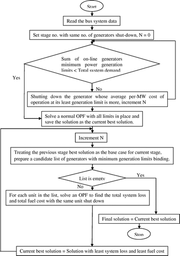
A technique similar to the heuristic technique is employed to achieve the reduction of the line losses and generation cost thereby leading to the shrinkage of wheeling cost (Castillo, Laird, Silva-Monroy, Watson, & O’Neill, Citation2016). Figure shows the flowchart for the technique proposed. The standard optimal power flow basically includes the generation dispatch at the least possible generation limits of generating units with the objective of diminution of network loss whereas the unit commitment technique implicates the mechanism of shutting down the generating units which are pricy to operate. The proposed algorithm runs an optimal power flow combined with unit commitment, shutting down the expensive generating units and finding a least cost cum least network loss effective unit commitment as well as finding generation dispatch at minimum generation limits, aiming at the reduction of both generating cost and wheeling cost.
The proposed algorithm for the wheeling cost calculation under UC condition is as follows:
| (1) | Read the bus system data. | ||||
| (2) | Perform the power flow analysis under UC condition. | ||||
| (3) | Apply Bialek’s power flow tracing scheme to determine each generating unit’s contribution using Equations (4) and (6) respectively. | ||||
| (4) | Determine each generating unit’s wheeling cost using the power flow based line-by-line wheeling cost computation methodology using Equation (7). | ||||
| (5) | Calculate each generating unit’s generation cost using Equation (8). | ||||
5. FACTS controllers
During the last two decades, the power system operation has been changed due to the increased load demand, technology development, change of electricity market behavior and renewable energies development (Karthikeyan et al., Citation2013). In addition to these changes, the involvement of the distributed generation, environmental pressure on the transmission expansion and smart grid concepts in the power system have made the power system a meshed network and its operation extremely complex (Ghahremani & Kamwa, Citation2013). In today’s electric power system, there is a mounting demand for the fast, trustworthy, accurate and multi-directional power flow control to increase the transmission network capacity for power flow control and for power quality improvement, by varying system parameters (NguyAen et al., Citation2011). To achieve this, proper management of the reactive power handling capacity of the transmission lines with the installation of the static power flow controlling equipment namely “FACTS controllers” is required. Their utilization provides better utilization of the existing transmission system assets, increases the transmission system reliability, increases the dynamic and transient grid stabilities, reduces the loop flows and increases the quality of supply for sensitive industries and environmental benefits (Ardakani & Blumsack, Citation2016).
FACTS controllers vary the bus voltage magnitude, transmission line reactance and transmission angle, either individually or in combination, to control the power flow (Rahimzadeh & Bina, Citation2011).
Shunt connected FACTS devices like SVC and STATCOM connected between the grid and ground either absorbs or generates the reactive power at the point of its connection thereby regulating the bus voltage magnitude; however, as this magnitude can be varied within certain limits, the power flow regulation by the voltage magnitude control is restricted and hence shunt devices mainly serve other purposes (Rahimzadeh et al., Citation2010).
SVC exchanges the inductive current or capacitive current to absorb or generate the reactive power to control the bus voltage magnitude at the point of its connection on the high-voltage electricity transmission networks (Singh et al., Citation2007). STATCOM injects the alternating current in quadrature with the grid voltage and emulates the inductive or capacitive impedance at the point of its connection. If the grid voltage dominates the STATCOM generated voltage, STATCOM withdraws the reactive power from the grid. STATCOM supplies the reactive power to the grid when its generated voltage dominates the grid voltage.
The location and rating of SVC for the minimization of the network loss and hence wheeling cost are determined by assuming both fixed capacitor and thyristor controlled reactor are of same rating.
The location and rating of STATCOM for the minimization of the network loss and hence wheeling cost are determined by assuming the coupling transformer leakage reactance equal to 0.15707 and DC voltage source is a capacitor whose voltage is given by Equation (9).(9)
(9)
where represents capacitor voltage,
represents bus voltage,
denotes bus reactive power demand and
denotes coupling transformer leakage reactance.
Series connected FACTS devices like TCSC and SSSC connected in series with the transmission line influence the line impedance to control the line flow (Bruno et al., Citation2016). Also these devices can improve both angular and voltage stabilities. TCSC provides a variable series capacitive reactance smoothly and SSSC varies the overall line reactive voltage drop, for power flow control (Sakr et al., Citation2016). Though SSSC output contains few harmonics like STATCOM output, it is effective for both light and heavy load conditions (Chang, Citation2014).
The location and rating of TCSC and SSSC for the minimization of the network loss and hence wheeling cost are determined by compensating each transmission line inductive reactance by −80 to 20 and 0 to 33% respectively.
Hybrid FACTS devices like UPFC and Interline Power Flow Controller (IPFC) are two-port devices, each connected in shunt and in series with the grid to exchange the active power between the shunt and series parts. These devices can simultaneously vary multiple system parameters like bus voltage magnitude, line reactance and transmission angle.
UPFC is the combination of a STATCOM and a SSSC, both coupled through a common DC link to allow the bi-directional active power flow between the output terminals of SSSC and STATCOM (Tiwari & Sood, Citation2013). It controls the bus voltage, line reactance and transmission angle concurrently or selectively, or both line active and line reactive power flows alternatively. In view of its control competence, UPFC can simultaneously control the voltage by continuously varying the in-phase or anti-phase voltage injection like a tap-changing transformer, series reactive compensation by injecting a voltage in quadrature with the line current like SSSC, and phase- shift by injecting a variable voltage with an angular relationship with respect to the bus voltage. However, due to the high-voltage voltage source converters and associated protection needs, UPFC is expensive and hence find limited practical applications (Verma & Gupta, Citation2006). With two series converters in different transmission lines interconnected by a joint DC link, IPFC compensates and controls the power flow in a multi-line transmission system. Each converter affords the reactive compensation of its own line and also can exchange the active power with the other converter through the shared DC link thereby providing active compensation too. IPFC can also be accompanied with an extra shunt converter for active power delivery from a suitable shunt bus. Thus IPFC can compensate both active and reactive power flows thereby optimizing the overall transmission system utilization (Kamarposhti & Lesani, Citation2011).
The assumptions made and compensation levels considered while analyzing the location and rating of shunt and series connected FACTS devices are taken into account while analyzing the location and rating of hybrid FACTS devices.
The proposed algorithm for the wheeling cost calculation in the presence of any optimally placed suitable FACTS device is as follows:
| (1) | Run the algorithm for the wheeling cost calculation shown in Figure . | ||||
| (2) | Comparing with the results obtained in step-1, determine the optimal location of properly rated FACTS device for the minimization of wheeling cost. | ||||
| (3) | Perform the power flow analysis after placing the properly rated FACTS device in the optimal location. | ||||
| (4) | Determine each generating unit’s contribution to each line’s real and reactive line power flows using Equations (4) and (6) respectively. | ||||
| (5) | Determine the wheeling cost of each generating unit using Equation (7). | ||||
| (6) | Determine each generating unit’s generation cost using Equation (8). | ||||
6. Case study
IEEE 30-bus system (Pai, Citation2006) is considered to study the influence of different types of optimally placed FACTS controllers on the bus system power losses, generation cost and wheeling cost, under both load-flow condition and UC condition.
Assuming the load demand of standard IEEE 30-bus system as the daily 1st hour power demand and the power demand at each load bus varies by ±20% of its 1st hour power demand during the remaining hours, the daily load demand is presented in Table . Assuming all generating units as IPPs and the daily load demand remains same throughout the year, the generation cost and wheeling cost are determined.
Table 1(a). Bus load data during the first twelve hours of a day
Table 1(b). Bus load data during the last twelve hours of a day
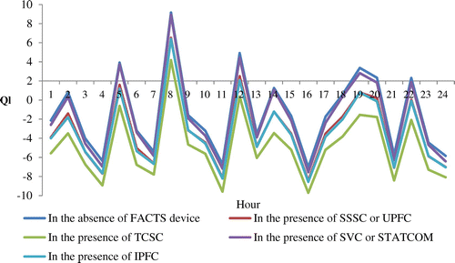
Table shows the hourly apparent power loss of the bus system in the absence of any FACTS controller. Table presents the hourly active power loss of the bus system in the presence of different optimally placed suitable FACTS devices. The optimal placement of any suitable FACTS device condensed the bus system real power loss. Figure exposes the hourly reactive power loss comparison in the presence of optimally placed suitable FACTS devices. During each hour, the bus system reactive power loss is reduced with proper placement of any suitable FACTS device. TCSC impacts the reactive power loss much more than any other FACTS device.
Table 2. Hour-wise network apparent power loss
Table 3. Hour-wise network active power loss comparison
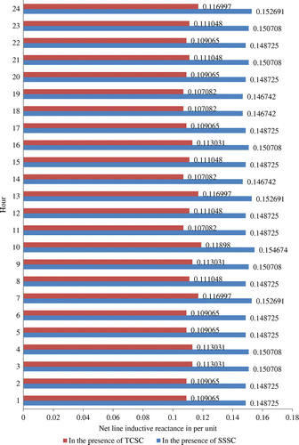
Figure shows the hourly net line reactance after the placement of SSSC and TCSC with the objective of the minimization of the network losses and hence wheeling cost. It is observed that SSSC of higher rating or TCSC of lower rating shown in Figure when placed in the transmission line numbered 5 has reduced the network apparent power loss to the most extent.
Table presents the hourly ratings of SVC and STATCOM optimally placed for the minimization of the network loss and hence wheeling cost. The connected devices have declined the bus system power losses to the same extent. Table presents the hourly ratings of UPFC and IPFC essential for the minimization of wheeling cost through the minimization of the bus system power losses. It is observed that UPFC when placed with its SSSC in the 5th transmission line and its STATCOM at the 5th bus has diminished the network apparent power loss to the utmost degree. Similar results are obtained with the optimally placed suitable IPFC with its two SSSCs connected in the transmission lines numbered 5 and 8 respectively.
Table 4. Ratings of SVC and STATCOM
Table 5. Ratings of UPFC and IPFC
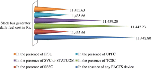
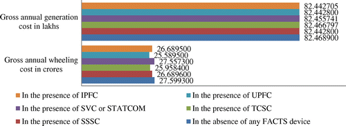
Figure compares the daily generation cost of slack bus generator in the absence of and in the presence of different optimally placed suitable FACTS devices. The slack bus generator daily generation cost is found to be least in the presence of IPFC. The remaining generating units located at buses numbered 2, 5, 8, 11 and 13 maintained the same daily fuel cost of Rs. 3,809.04, Rs. 1,494.23, Rs. 2,975.20, Rs. 1,483.85 and Rs. 1,389.09 respectively without and with the usage of different FACTS controller types. Table compares the generator-wise daily wheeling cost in the absence of and in the presence of different optimally placed suitable FACTS devices. The overall daily wheeling cost is found to be least in the presence of UPFC. Figure compares the gross annual generation and wheeling costs without and with the FACTS devices usage. The total annual generation and wheeling costs are found to be least with the existence of IPFC and UPFC respectively.
Table 6. Generator-wise daily wheeling costs
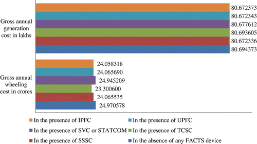
Table depicts the hourly apparent power loss of the bus system in the absence of and with the proper placement of different FACTS devices under UC condition. The bus system apparent power loss is found to be declining under UC condition in the absence of and in the presence of different suitable optimally placed FACTS devices. The reduction of the network apparent power loss leads to the shrinkage of wheeling cost. Figure compares the gross annual generation and wheeling costs under UC condition in the absence of and in the presence of different optimally placed suitable FACTS devices. The gross annual generation and wheeling costs are found to be least in the presence of optimally placed suitable SSSC and TCSC respectively.
Table 7. Hour-wise network apparent power loss comparison under UC condition
7. Conclusions
Practically the wheeling party network loading involves the flow of apparent power through it leading to the rise of both active and reactive power losses in it. Wheeling cost computation methodology considering apparent power wheeling is essential for arriving at the actual wheeling cost. Optimal placement of custom power devices for the reduction of wheeling cost via the reduction of network losses is essential owing to physical and economic constraints. Reduction of the network power loss during each hour of the study period is achieved with the optimal placement of suitable FACTS controllers of different types. The shrinkage of the network power loss implies the shrinkage of both generation and wheeling costs. IEEE 30-bus system case study is performed for verifying the proposed algorithms efficacy for finding the shrinkage in both generation cost and transmission pricing in conjunction with the placement of properly rated FACTS device in optimal location. The influence of the optimally placed suitable IPFC is more on the generation cost and that of UPFC is more on the wheeling cost. The network power loss and hence both generation and wheeling costs are found to be reduced much under UC condition; however, the optimally placed suitable SSSC influenced the generation cost much and the optimally placed suitable TCSC effected the wheeling cost more. Probable compensation of generation cost and definite compensation of wheeling cost take place among the interconnected generating units.
| Nomenclature | ||
| no. | = | Number |
| Rs. | = | Rupees |
| C | = | Capacitance of SVC in μF |
| L | = | Inductance of SVC in mH |
| Vs | = | DC energy source rating of STATCOM in kV |
| X | = | Net line inductive reactance in per unit |
| Pl | = | Network active power loss in MW |
| Ql | = | Network reactive power loss in MVAR |
| Sl | = | Network apparent power loss in MVA |
Funding
The authors received no direct funding for this research.
Additional information
Notes on contributors
Kranthi Kiran Irinjila
Irinjila Kranthi Kiran was born on 31st July, 1974. He received BTech degree in Electrical and Electronics Engineering (EEE) in 1996 from Nagarjuna University, Guntur, Andhra Pradesh. He completed MTech (Power Systems) course in EEE with emphasis on High Voltage Engineering in 2005 from JNT University, Hyderabad, Telangana. He is pursuing PhD in the area of Power Systems under the guidance of Dr Askani Jaya Laxmi, Professor of EEE Department and Coordinator for Centre for Energy Studies, JNTU College of Engineering, Hyderabad, Telangana. He has two years of Industrial experience and eighteen years of teaching experience. He presented and published research papers at and in national and international level conferences and journals on different embedded and incremental wheeling cost computation methodologies under conditions of load-flow as well as unit-commitment, in the absence of FACTS devices. His research interests are in the areas of power system restructuring and wheeling cost methodologies. He is a Member of IEEE and Life Member of Indian Society for Technical Education.
References
- Ardakani, M. S. , & Blumsack, S. A. (2016). Transfer capability improvement through market-based operation of series FACTS devices. IEEE Transactions on Power Systems , 31 (5), 3702–3714.10.1109/TPWRS.2015.2508720
- Bruno, S. , Carne, G. D. , & Scala, M. L. (2016). Transmission grid control through TCSC dynamic series compensation. IEEE Transactions on Power Systems , 31 (4), 3202–3211.10.1109/TPWRS.2015.2479089
- Castillo, A. , Laird, C. , Silva-Monroy, C. A. , Watson, J. P. , & O’Neill, R. P. (2016). The unit commitment problem with AC optimal power flow constraints. IEEE Transactions on Power Systems , 31 (6), 4853–4866.10.1109/TPWRS.2015.2511010
- Chang, Y. C. (2014). Multi-objective optimal thyristor controlled series compensator installation strategy for transmission system loadability enhancement. IET Generation, Transmission & Distribution , 8 (3), 552–562.10.1049/iet-gtd.2013.0047
- Cvijić, S. , & Ilić, M. D. (2014). Part I: A new framework for modeling and tracing of bilateral transactions and the corresponding loop flows in multi-control area power networks. IEEE Transactions on Power Systems , 29 (6), 2706–2714.10.1109/TPWRS.2014.2312376
- Ghahremani, E. , & Kamwa, I. (2013). Optimal placement of multiple-type FACTS devices to maximize power system loadability using a generic graphical user interface. IEEE Transactions on Power Systems , 28 (2), 764–778.10.1109/TPWRS.2012.2210253
- Kamarposhti, M. A. , & Lesani, H. (2011). Effects of STATCOM, TCSC, SSSC and UPFC on static voltage stability. Electrical Engineering , 93 (1), 33–42.10.1007/s00202-010-0187-x
- Karthikeyan, S. P. , Jacob Raglend, I. , & Kothari, D. P. (2013). Impact of FACTS devices on exercising market power in deregulated electricity market. Frontiers in Energy , 7 (4), 448–455.10.1007/s11708-013-0262-x
- Leite Da Silva, A. M. , De Carvalho Costa, J. G. , & Monteiro Mattar, C. (2006). A probabilistic approach for determining the optimal amount of transmission system usage. IEEE Transactions on Power Systems , 21 (4), 1557–1564.10.1109/TPWRS.2006.883672
- McGovern, T. , & Hicks, C. (2004). Deregulation and restructuring of the global electricity supply industry and its impact upon power plant suppliers. International Journal of Production Economics , 89 (3), 321–337.10.1016/j.ijpe.2004.03.006
- NguyAen, T. T. , Nguyen, V. L. , & Karimishad, A. (2011). Transient stability-constrained optimal power flow for online dispatch and nodal price evaluation in power systems with flexible AC transmission system devices. IET Generation, Transmission & Distribution , 5 (3), 332–346.10.1049/iet-gtd.2008.0527
- Nojeng, S. , Hassan, M. Y. , Said, D. M. , Abdullah, M. P. , & Hussin, F. (2014). Improving the MW-mile method using the power factor-based approach for pricing the transmission services. IEEE Transactions on Power Systems , 29 (5), 2042–2048.10.1109/TPWRS.2014.2303800
- Orfanos, G. A. , Georgilakis, P. S. , & Hatziagyriou, N. D. (2013). A more fair power flow based transmission cost allocation scheme considering maximum line loading for N-1 security. IEEE Transactions on Power Systems , 28 (3), 3344–3352.10.1109/TPWRS.2013.2243175
- Pai, M. A. (2006). Computer techniques in power system analysis (2nd ed., pp. 228–228). India : Tata McGraw-Hill Publishing Company Ltd.
- Rahimzadeh, S. , & Bina, M. T. (2011). Looking for optimal number and placement of FACTS devices to manage the transmission congestion. Energy Conversion and Management , 52 (1), 437–446.10.1016/j.enconman.2010.07.019
- Rahimzadeh, S. , Tavakoli, M. , & Viki, B. A. H. (2010). Simultaneous application of multi-type FACTS devices to the restructured environment: Achieving both optimal number and location. IET Generation, Transmission and Distribution , 4 (3), 349–362.10.1049/iet-gtd.2009.0287
- Rao, M. S. S. , Soman, S. A. , Chitkara, P. , Gajbhiye, R. K. , Hemachandra, N. , & Menezes, B. L. (2010). Min-Max fair power flow tracing for transmission system usage cost allocation: A large system respective. IEEE Transactions on Power Systems , 25 (3), 1457–1468.10.1109/TPWRS.2010.2040638
- Sakr, W. S. , El-Sehiemy, R. A. , & Azmy, A. M. (2016). Optimal allocation of TCSCs by adaptive DE algorithm. IET Generation, Transmission & Distribution , 10 (15), 3844–3854.10.1049/iet-gtd.2016.0362
- Saravanan, B. , Das, S. , Sikri, S. , & Kothari, D. P. (2013). A solution to the unit commitment problem-a review. Frontiers in Energy , 7 (2), 223–236.10.1007/s11708-013-0240-3
- Sedaghati, A. (2006). Cost of transmission system usage based on an economic measure. IEEE Transactions on Power Systems , 21 (2), 466–473.10.1109/TPWRS.2006.873133
- Singh, J. G. , Singh, S. N. , & Srivastava, S. C. (2007). An approach for optimal placement of static VAr compensators based on reactive power spot price. IEEE Transactions on Power Systems , 22 (4), 2021–2029.10.1109/TPWRS.2007.907374
- Sood, Y. R. , Padhy, N. P. , & Gupta, H. O. (2002). Wheeling of power under deregulated environment of power system-a bibliographical survey. IEEE Transactions on Power Systems , 17 (3), 870–878.10.1109/TPWRS.2002.800967
- Su, C. T. , Liaw, J. H. , & Li, C. M. (2006). Power-flow tracing and wheeling costing considering complex power and convection lines. IEE Proceedings C , 153 (1), 1–10.
- Tiwari, P. K. , & Sood, Y. R. (2013). An efficient approach for optimal allocation and parameters determination of TCSC with investment cost recovery under competitive power market. IEEE Transactions on Power Systems , 28 (3), 2475–2484.10.1109/TPWRS.2013.2243848
- Unsihuay, C. , & Saavedra, O. R. (2006). Transmission loss unbundling and allocation under pool electricity markets. IEEE Transactions on Power Systems , 21 (1), 77–84.10.1109/TPWRS.2005.857838
- Verma, K. S. , & Gupta, H. O. (2006). Impact on real and reactive power pricing in open power market using unified power flow controller. IEEE Transactions on Power Systems , 21 (1), 365–371.10.1109/TPWRS.2005.857829
- Xu, Z. , Dong, Z. Y. , & Wong, K. P. (2006). Transmission planning in a deregulated environment. IEE PROC-C , 153 (3), 326–334.
- Zhu, S. , Wu, L. , Guan, X. , & Wu, J. (2016). SCUC-based optimal power tracing approach for scheduling physical bilateral transactions and its verification via an integrated power-money flow analysis. IET Generation, Transmission and Distribution , 10 (10), 2399–2409.10.1049/iet-gtd.2015.1160

