
 ?Mathematical formulae have been encoded as MathML and are displayed in this HTML version using MathJax in order to improve their display. Uncheck the box to turn MathJax off. This feature requires Javascript. Click on a formula to zoom.
Abstract
In this article, an algorithm for mitigating distance measuring equipment (DME) interference in L-band digital aeronautical communication system type 1 (LDACS1)-based aeronautical communication systems is presented. The LDACS1 is a broadband system based on orthogonal frequency-division multiplexing (OFDM) is the most promising candidate for the future air-to-ground (A/G) communications. LDACS1 is operating as an inlay system and limited to the 500 kHz spectral gap between the two adjacent DME channels of bandwidth 1 MHz. In this work, a decision directed noise estimation (DDNE) approach to mitigating the pulsed interference from DME for LDACS1 system is proposed. It improves the conventional blanking and clipping approach for interference mitigation, which typically distorts the entire received signal, by combining the blanked and the original signal. The proposed designs are carried out for both cases of AWGN channel and En-Route aeronautical channel. The simulation results highlight the impact of DME interference onto the LDACS1 system and show the performance improvement of the proposed method compared to conventional interference mitigation methods in terms of bit error rate (BER).
PUBLIC INTEREST STATEMENT
Current efforts to find solution to the spectrum scarcity problem in a current having very high frequency (VHF) spectrum used for aeronautical communication, FCI and ICAO jointly proposed to use L-band (UHF) in the frequency range of 960–1164 MHz instead of VHF band if coexistence with legacy systems is ensured. As a result, interference from various legacy systems operated in the UHF band would become a bottleneck of the new air-to-ground (A/G) communication system in the UHF band. LDACS type 1 (LDACS1) and LDACS type 2 (LDACS2), are preselected as the most promising candidates for future aeronautical communications operated in L-band. In this article, an algorithm for mitigating the pulsed interference from legacy DME system to LDACS-based aeronautical communication systems is presented.
1. Introduction
Over the past two decades, the air transport industry has experienced continuous growth and the demand for passenger air traffic is forecast to double the current level by about 2025 (EUROCONTROL, Citation2008). The growth of air traffic in the airport required an advanced and efficient air traffic management (ATM) infrastructure that is able to cope with the spectral scarcity problem and also the ever-growing demand for more bandwidth and higher data rates. The current air-to-ground (A/G) communication system uses very high frequency (VHF) aeronautical band between 118 − 137 MHz. The broadband VHF (B-VHF) system is presented as an alternative A/G communication system for ATM (Schnell et al., Citation2008a). The prime objective of the B-VHF system is to demonstrate that it is feasible to make a multi-carrier-based overlay system for future ATC communications in the VHF band without producing interference to the legacy VHF systems. The B-VHF system is capable of fulfilling expectations of future ATC communications like high efficiency, increased capacity and improved communications system safety. However, the VHF band is already saturated. In order to overcome the limited availability of spectrum in the VHF band for the aeronautical communication system, the Future Communications Infrastructure (FCI) (EUROCONTROL, Citation2007) and International Civil Aviation Organization (ICAO) recommended the use of L-band 960−1164 MHz (Gräupl & Mayr, Citation2015; Schnell et al., Citation2008b), termed L-band digital aeronautical communication system (LDACS).
The future communications study (FCS) (Future Communications Study Operational Concepts and Requirements Team, Citation2007) has preselected two technology decisions for the LDACS, specifically LDACS type 1 (LDACS1) and LDACS type 2 (LDACS2), as the most promising candidates for future aeronautical communications. LDACS1 is a broadband candidate technology using orthogonal frequency-division multiplexing (OFDM) for the future A/G and air-to-air (A/A) mode communication system (Sajatovic et al., Citation2009). Due to the limited amount of available spectrum in L-band, the transmission bandwidth for LDACS1 is limited to the 500 kHz spectral gap between the two adjacent distance measuring equipment (DME) channels of bandwidth 1 MHz, for each forward and reverse link (FL/RL). The frequency-division duplex (FDD) is applied to split up this limited bandwidth between FL and RL. The second choice, named LDACS2 (Fistas & Phillips, Citation2007), is a narrowband single-carrier technology with 200 kHz transmission bandwidth. It uses a Gaussian minimum shift keying modulation (GMSK). For duplexing, time-division duplex (TDD) is chosen. One of these two candidates (LDCAS1 or LDACS2) will be selected for deployment in aeronautical communications.
The LDACS is the system in the FCI for L-band aeronautical communications. It is expected to use the 960–1164 MHz band, allocated to the Aeronautical Mobile (Route) Service [AM(R)S] by the International Telecommunication Union (ITU). The L-band is shared by various legacy systems. The LDACS system is deployed as an inlay system in the spectral gaps between two adjacent channels used by the DME as well as the non-inlay deployment in unused portions of the L-band. Figure . Shows the L-band spectrum usage (Epple & Schnell, Citation2015; Mostafa & Schnell, Citation2015; Schnell, Epple, Shutin, & Schneckenburger, Citation2014; Thiasiriphet, Schneckenburger, & Schnell, Citation2015). The band is shared by DME (distance measuring equipment), SSR (secondary surveillance radar), JTIDS (Joint Tactical Information Distribution System) and MIDS (Multifunction Information Distribution System). GSM900 is adjacent to the lower edge of the spectrum. DME ground markers are assigned 1 MHz band in the regions marked for DME. So, additional parts of the band may be available for LDACS. Figure shows the FL/RL spectrum possibilities for LDACS1 and LDACS2. Note that LDACS1 needs a paired spectrum with 63 MHz spacing between the FL/RL. LDACS2 will need a 200 kHz channel in the lower L-band 960–975 MHz region.
Figure 1. L-band spectrum usage (Jain et al., Citation2011 ).
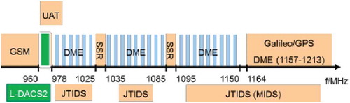
Figure 2. Interference between L-DACS and DME.
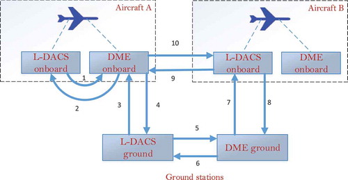
Figure 3. LDACS1 FL frame structure (Jain et al., Citation2011 ).
A detailed analysis of potential levels of interference from these various legacy systems can be found in (Gligorevic et al., Citation2011; Jain, Templin, & Yin, Citation2011). Among all, one of the most interfering systems is the DME, which continuously evaluates the slant distance between the aircraft and ground beacons, and utilizes most of the 960−1164 MHz spectrum. Various possible interferences between LDACS and DME for both co-site and co-channel environments are depicted in Figure .
1.1. Possible interference scenario between LDACS1 and DME based on spectrum allocation
➢ L-DACS1 spectrum for FL: 960–1009 MHz and DME spectrum for FL: 962–1213 MHz
➢ L-DACS1 spectrum for RL: 1048–1157 MHz DME spectrum for RL: 1025–1150 MHz
DME interference effect on LDACS1:
LDACS1 FL is only affected by DME GS (FL) not as DME airborne station (AS) (RL) are not active in this part of the spectrum
LDACS1 RL is affected by both the DME GS (FL) and DME AS (RL)
LDACS 1 interference effect on DME:
DME FL is affected by both the LDACS1 GS (FL) and LDACS1 AS (RL).
DME RL is only affected by LDACS1 AS (RL) not as LDACS1 GS (GL) are not active in this part of the spectrum.
1.2. Possible interference scenario between LDACS2 and DME based on spectrum allocation
➢ L-DACS2 spectrum for FL: 960–975 L-DACS2 spectrum for RL: 960–975
DME interference effect on LDACS1:
LDACS2 FL and RL are only affected by DME GS (FL)
LDACS 2 interference effect on DME:
DME FL is affected by both the LDACS2 GS (FL) and LDACS2 AS (RL).
DME RL is not affected by both the LDACS2 AS (RL) and LDACS2 GS (GL).
An important issue that needs to be addressed in LDACS1 system is the radio frequency compatibility as it has to coexist with several legacy systems that are already operating at L-band (Gligorevic et al., Citation2011). The band is shared by various legacy systems such as by secondary SSR, DME, MIDS and JTIDS. In particular, the DME is a strong interference to LDACS1 due to the inlay deployment approach and narrow frequency separation between the two systems. DME is the radio navigation technology, which measures the slant distance between the aircraft, and the ground station (GS) operates in the UHF frequency spectrum between 960−1164 MHz. Various possible interference scenarios between LDACS1 and DME for both co-site and co-channel environments are analyzed in (Gligorevic et al., Citation2011). The LDACS1 will be exposed to severe pulsed interference from the DME channels with 500 kHz offset to the LDACS1 centre frequency, and the pulsed interference from all the interfering DME stations are superimposed with each other. The effect of DME interference onto the LDACS1 leads to high performance loss as the transmission power of DME interference is high compared to that of LDACS1.
Pulse blanking and pulse clipping (PC) are two well-known time domain approaches for pulsed interference mitigation (Brandes et al., Citation2009; Brandes & Schnell, Citation2009; Epple & Schnell, Citation2011). In pulse blanking, the received samples are set to zero when the power of the samples exceeds a certain threshold level. In the case of PC, the received samples exceeding a certain threshold are set to the threshold value rather than setting to zero as for pulse blanking. These approaches have the advantage of simplicity, but their main drawback is that the desired OFDM signal will also be removed along with the interference signal. Also, it is hard to determine the optimal thresholds for both techniques. Removal of the desired signal in OFDM-based LDACS1 leads to inter-carrier interference (ICI) that significantly degrades the performance. Frequency domain approaches for mitigating the impulsive interference in OFDM system has also been proposed, but these methods have high computational complexities (Haring & Vinck, Citation2003; Zhidkov, Citation2003). A Markov model can be well integrated into a memoryless Gaussian mixture (GM) model to introduce memory between impulse noise samples (Shongwe, Vinck, & Ferreira, Citation2015). For efficient statistical processing of interference, (Saaifan, Elshahed, & Henkel, Citation2017) a GM distribution is adopted to model the impulsive nature of DME signals. It helps to design an optimum receiver for mitigating DME interference from LDACS1. The decision directed noise estimation (DDNE)-based mitigation method has been proposed in literature to mitigate the impulse noise in the OFDM system (Armstrong & Suraweera, Citation2004). In DDNE method, the impulsive noise component in the received signal is detected and deleted from the input sample before the final OFDM demodulation.
A comprehensive study is provided on available AG channel measurement campaigns, large and small scale fading channel models, their limitations, and future research directions for unmanned aerial vehicles (UAV) communication scenarios (Khuwaja, Chen, Zhao, Alouini, & Dobbins, Citation2018). The channel modelling of low altitude A/G communication is proposed and the performance analysis of low altitude UAV-enabling A/G communication systems is presented in terms of channel capacity and the throughput (Qiu, Chu, Calvo-Ramirez, Briso, & Yin, Citation2017). More recently, our work in (Raja, Vinod, & Madhukumar, Citation2015) has studied an interference mitigation method based on DDNE for the LDACS1 FL system to remove the pulse interference from the DME station with minimal impact on the desired OFDM signal. The work considers the more ideal case that additive white Gaussian noise (AWGN) channel is available between GS and Aircraft station (AS). This article is a further development of (Raja et al., Citation2015) to the aeronautical communication employ more complex aeronautical channel with Doppler shift. (Schneckenburger et al., Citation2016) Flight trials conducted to investigate the characteristics of the L-band A/G channel for positioning applications. The power delay and Doppler power profiles, as well as the time-of-arrival estimation accuracy, are also presented (Schneckenburger et al., Citation2016). Estimation of aircraft distances from a receiver at an airport using transponder signal strength information is proposed in (Mott, Citation2018). The received signal strength data are processed using a digital adaptive first-order low-pass Butterworth filter in tandem with a Rayleigh maximum likelihood estimator of the signal variance.
Here we consider the pulsed interference from one or more DME GSs at the transmission rate of 3600 pulse pairs per second (ppps). The mitigation of the impulsive interference is done in two stages. In the first phase, the estimation of interferences from one or multiple DME stations is performed on the received signal of the LDACS1 system. In the second stage, the estimated interference is subtracted from the received signal before the final OFDM demodulation to obtain the desired LDACS1 signal. Preliminary decisions are made about the transmitted data (i.e. estimation of transmitted data) and from these an estimate is made of the interference in the received signal. The estimation of the degree of interference is done based on the preset threshold value. If the amplitude of the estimated interference sample has exceeded the threshold value, then the estimated value is subtracted from the original received signal before the OFDM demodulation stage and the amplitude of the samples below the threshold is set to zero. We conducted simulations to evaluate the effectiveness of the DDNE approach in mitigating DME interference on LDACS1 system. The simulations are done for LDACS1 FL in a flat fading channel and aeronautical channel which includes different Doppler shift. The rest of this article is organized as follows: Section 2 shows LDACS1 System Overview. In Section 3 shows the system model for the conventional and proposed designs. In Section 4 shows the DME Interference and A/G Channel Modelling. In Section 5 shows the performance of the proposed design with simulation results. And Section 6 concludes the article.
2. LDACS1 system overview
L-DACS1 supports two different ways of communication, one A/G communication and a second one for A/A communication. In our work, we mainly focus only on A/G communication. It supports the data communication and also supports the voice communication as optional. The A/G communication assumes star topology between the centralized GS and multiple aircrafts within the LDACS1 cell (i.e. operating range of GS). For the FL, the OFDM is chosen a modulation technique, whereas, in the RL, a combination of orthogonal frequency-division multiple access (OFDMA) and time-division multiple-access (TDMA) is applied. The FL and RL directions are separated by FDD. The LDACS1 and LDACS2 system parameters are depicted in Table and OFDM parameters for LDACS1 are shown in TABLE . The large number of different combinations of modulation and coding techniques is used for modern communication system. Utilizing those, the transmission can be continuously adjusted to the channel condition, interference conditions, and user requirements. In LDACS1, the coding comprises of a Reed-Solomon (RS) code linked with a convolutional coding technique. As modulation technique, quadrature phase shift keying (QPSK) is used.
Table 1. System parameters for L-DACS1 and L-DACS2 (Jain et al., 2011)
Table 2. OFDM parameters for LDACS1 (Jain et al., 2011)
2.1. LDACS1 frame structure for FL and RL
Each OFDM frame is composed of multiple OFDM symbols. Different frame types are distinguished based on their functionality. All the frames in FL and RL are arranged into super-frames (SF) and multi-frames (MF) as shown in Figures and , respectively (Saaifan et al., Citation2017). The SF structure for FL is depicted in Figure , which is composed of one broadcast (BC) frame followed by four MFs. Each multi frame in the FL direction is divided into nine frames for payload data and common control (CC). The SF in the RL direction is composed of random access (RA) frame followed by four MF, which depicted in Figure . Each MF in the RL direction is structured into small segments called tiles. Each tile belongs to either a data segment or dedicated control (DC) segment. Each AS is allowed to use only one RA SF and only one DC tile per SF. In FL, the BC frame is used to BC cell-specific information from GS to AS and the CC is used to assign resources and acknowledge to the AS. In the RL, the RA is used for the purpose of initial cell entry for the AS and DC frame is used to request transmission resources and to signal acknowledges.
Figure 4. LDACS1 RL frame structure (Jain et al., Citation2011 ).
2.2. LDACS1 system model
In this article, we consider the LDACS1 FL communication between centralized GS and Aircrafts. The basic functionality of GS transmitter is illustrated in Figure (Epple & Schnell, Citation2014; Schnell et al., Citation2014). At the LDACS1 FL transmitter side, the input sequence is initially encoded with external encoder (i.e. RS encoder) followed by the internal encoder (i.e. convolutional encoder) and the coded bits are interleaved using a permutation interleaver. The interleaved bits are mapped into modulated symbol using a symbol mapper i.e. QPSK, modulated symbols
, are arranged in a vector
to form an OFDM symbol. The OFDM symbols are mapped onto the LDACS1 FL frames by just positioning the complex symbols onto the time-frequency plane using a frame composer. The block of
symbols,
is transformed into a block of
symbols
by adding
zeros in correspondence of the first seven and last six subcarrier and on the DC subcarrier. The
th transmitted OFDM symbol after the insertion of cyclic prefix of length
is represented as
Figure 5. Block diagram of LDACS1 GS transmitter.
where and
. The transmitted vector of
th OFDM symbol
is then used as input to a multipath channel with an impulse response
. The received signals are corrupted by AWGN
. The impulsive interference vector corresponding to the n
th OFDM symbol is
. The time domain received signal is composed of the transmitted OFDM signal
affected by the multipath channel and AWGN. The received signal of the
th OFDM symbol with the channel impulse response
including cyclic prefix is represented as
When sampling the received signal of
th OFDM symbol with the sampling frequency of the OFDM signal, an a liasing effect occurs due to the mismatch of the sampling frequency of the OFDM signal and the DME signal spectrum. As a result, the undesired part of the OFDM signal will fall into the OFDM signal spectrum. To solve this issue, an anti-aliasing filter in combination with oversampling is applied. The
th oversampled OFDM symbol is denoted by
and it is represented in time domain as (Brandes & Schnell, Citation2009)
where denotes the desired OFDM signal affected by channel,
and V denotes the over sampling factor. The transmitted OFDM signal
Is recovered from the oversampled sequence
by mean of an FFT with size increased to
in accordance to the oversampling factor. The FFT output for the
th subcarrier before equalizer is
where is the samples of transmitted symbol,
is the channel impulse response,
is the AWGN in a frequency domain and
is the DME interference in frequency domain.
3. DME interference and A/G channel modelling
The DME is a radio navigation system that operates in the 960–1215 MHz frequency range and has been used in all airplanes to find the slant distance between the aircraft and DME ground beacons. The distance between aircraft and DME GS is measured based on following steps. It starts on the interrogator at aircraft transmitting a stream of Gaussian-shaped pulse pairs to the transponder at the DME GS. After a certain delay at the DME GS, the transponder sends back the received signal to the interrogator. The interrogator finds the distance between the aircraft and GS by measuring the travel time duration of the pulse pair. It consists of pair of Gaussian shaped pulses with a separation of = 12 or 36
. One pulse pair in baseband is given by (Gao, Citation2007; Thiasiriphet et al., Citation2015)
where . It leads to a width of 3.5
at 50% percentage of maximum amplitude. Due to the nature of Gaussian shaped pulse in DME system, it also produces a Gaussian shaped spectrum in the frequency domain. The Gaussian shaped spectrum is modulated with a cosine. It can be described by
To show the impact of DME interference onto the FL of the LDACS1 system, the interference model in Gao (Citation2007) and Thiasiriphet et al. (Citation2015) is used. To create the DME interference signal corresponding to the LDACS1 system, the baseband DME pulse pairs are modulated to the relative carrier frequency of the channel to 0.5 MHz left and to the 0.5 MHz right of the LDACS1 system bandwidth. The total interference signal at LDACS1 system in a certain time interval
is composed of the contribution from
DME stations that are operating on the
offset to the centre frequency of the LDACS1 system. The DME interfering signal that affects LDACS1 system can be expressed as (Gao, Citation2007; Thiasiriphet et al., Citation2015)
where - total number of interfering DME stations,
- total number of pulse pair in the particular time interval for the
th interfering DME station,
,
- power and phase of the pulse pair, respectively,
- the relative carrier frequency of the
th interfering DME station and
- starting times of the
th pulse pairs of the
th DME station. The resulting diagram of a possible interference between the LDACS1 system and DME on both on the ground and aircraft is shown in Figure . In particular, this article focuses on the interference at the LDACS1 receiver at aircraft from the DME transponder at GSs. Since the LDACS1 FL and DME transponders are intended to be operated in the sub-band (979–1025 MHz), only DME transponder at GSs cause interference at the LDACS1 receiver at aircraft.
The free space path channel model which is more suitable for the aeronautical communication system is introduced. A robust time delay estimation (TDE)-based direction-finding method for multipath signals in the presence of impulsive noise is proposed (Haas, Citation2002; Shan et al., Citation2014). The simplest form of the channel model assumes that the received signal strength is only affected by the AWGN and travelled distance. The AWGN channel model is assumed whenever the noise samples are statistically independent and follow a complex Gaussian distribution with mean and standard deviation
for both in-phase and quadrature components. The different phase of the flight lead to different aeronautical channel scenarios: En-Route, Arrival, Taxi and Parking. Each of these channels is characterized by the type of fading, Doppler and delay. All the aeronautical channel consists of both line of sight (LOS) and non-LOS path that contains a group of reflected, delayed paths. The LOS path can be characterized by Rician fading. The rice factor
is a power ratio between the LOS path and average power of the pth scattered component, is given by (Schneckenburger et al., Citation2016)
where is the amplitude of the LOS path and
is the average power of the pth scattered component. When the value of
and
, the aeronautical channel is approximated by AWGN channel and for the value of
and
, the aeronautical channel is well approximated by the Rayleigh fading channel.
In the case of En-Route scenario, the multipath channel comprises of a LOS path, a group of reflected and delayed paths. The frequency content of the received signal is shifted due to the movement of the aircraft relative to the GS is called the Doppler Effect. The En-Route scenario is characterized by fast fading. The difference between the transmitted and received frequency is called as Doppler frequency, which can be written as. Where
the maximum Doppler frequency and
is the angle of arrival of the received signal. The
is given by (Haas, Citation2002)
where,
and
are the speed of the aircraft carrier frequency and speed of light, respectively. When the aircraft is moving towards the GS, the resulting
is positive and expressed as
. On the other hand,
is negative when the aircraft is moving away from the GS, and the received frequency is
. The value of
may vary from
to
. The scattered waves arrive from different direction relative to aircraft heading with different time delays. As a consequence, they undergo different Doppler shifts. This non-isotropical distribution result in a Doppler probability density function that is only a part of the classical 2-D isotropic Doppler density function derived Jakes distribution (Shongwe et al., Citation2015; Zhidkov, Citation2003). In this work, we consider the Rayleigh fading channel is modelled using Jakes model. A Jakes Doppler power spectrum assumed for this channel is (Haas, Citation2002)
Doppler power spectrum gives the statistical power distribution of the channel for a transmitted signal at one frequency, where the power delay profile (pdp) gives the statistical power distribution of the channel for a transmitted signal at a particular amount of time. The pdp is generated by a set of delayed path. Based on the type of environment, the pdp is varying. The pdp for the delay is given by
where is the delay spread. The delay-Doppler power spectrum is defined from (12) and (13) as
The general input-output discrete-time channel model is expressed as (Mott, Citation2018)
where - channel output,
- channel input, transmitted signal, P- total number of scattered paths and
- fading behaviour of pth path, which is a complex Gaussian process.
4. Conventional and proposed interference mitigation methods
Due to the fact that the power level of the wanted received LDACS1 signal is normally lower than the unwanted DME signal, the DME pulses can be identified in the time domain received signal. Most basic and easiest methodologies for detecting and mitigating the DME interference are pulse blanking (PB) and PC. It is used at the LDACS1 receiver before OFDM demodulator to remove DME pulsed interference from receiving signals. The pulse blanking removes all samples of the received signal with amplitude exceeding a predefined threshold (Epple, Shibli, & Schnell, Citation2011). The received signal in time domain after pulse blanking yields
In PC, the subcarrier having amplitude more than threshold value is clipped. The received signal after PC yields
where and
are threshold value for pulse blanking and PC, respectively. Despite the fact that BN does remove the impulsive interference, it also removes the entire received LDACS1 signal during the blanking interval, in spite of just a small amount of the transmission bandwidth may be influenced by the interference which is a huge downside of this technique 33]. In this article, we consider the LDACS1 FL communication between centralized GS and Aircrafts. Figure shows the block diagram of a LDACS1 receiver with the DDNE mitigation technique. At the aircraft receiver, the faded versions of the signals are received with DME interference. The received LDACS1 samples for p
th OFDM symbol is given by
Figure 6. Proposed DDNE approach for LDACS1 aircraft receiver.
where is the useful
th OFDM symbol with impulse response of the multipath channel (
) and
is the total interference at the input that includes both the impulsive (
) and AWGN (
). The received samples at the aircraft are serial-to-parallel converted to form the vector of N complex samples and it is passed through
-point FFT to obtain the data symbol on each subcarrier (
). Despite the fact that this symbol contains the impact of impulsive interference, these symbols pass through the decision device to make preliminary decision about the transmitted data (
) based on the received data (
). The interference component of the
is
. By subtracting
from
, the observed interference is obtained and it is expressed as
As a result, if the received subcarriers are correctly decoded, the observed interference in that subcarriers is exactly equal to the received interference. In the situation where the received subcarriers are wrongly decoded, then the observed interference value will be added to the decision interference. The IFFT is applied in the vector to generate the discrete time domain observed interference vector
. The time domain interference signal
is passed through the interference estimation block where the interference estimation algorithm is used to estimate the presence and degree of interference. The estimation of the presence and degree of interference is done based on the preset threshold value and it work as follows
where and
are scale factor and threshold value, respectively. Then the estimated interferences are subtracted from the original received time domain signal before the LDACS1 demodulation block to remove the DME interference. The OFDM samples after mitigating the interference to the LDACS1 demodulator is expressed as follows
After removing the cyclic prefix and suffix, the extracted part of an each OFDM symbol is converted back to the frequency domain by applying FFT operation. The FFT output for the subcarrier is represented as follows,
Based on the received pilot symbol, the complex channel response coefficients are estimated by channel estimation and equalization process. At the output of the frame decomposer, all the frames are decomposed into a useful symbol by extracting the data symbols in time direction from the time-frequency direction and convert them on a data stream followed by demodulation block.
5. Simulation results
This section presents the performance of the DDNE for mitigating the DME interference in LDACS1 system. The Mat lab simulation has been used for validating the performance of the proposed system. The performance of the proposed system over the flat fading channel is measured in terms of bit error rate (BER). The QPSK is applied to modulate the data. For outer coder and inner coder, a RS code of rate
in concatenation with a
convolutional code with rate
are applied. All OFDM symbols within one LDACS1 FL data/CC frame is used for data transmission. 2442 subcarriers are used to carry the data symbol out of 3328 subcarrier available, including pilot and null subcarriers. Here we consider both the AWGN channel and En-Route aeronautical channel is to analyze the performance degradation of the LDACS1 receiver at aircraft due to DME interference from one or more DME GSs. All the DME GSs that operate in the channels at ±0. 5 MHz offset to the L-DACS1 FL centre frequency are considered as interfering DME GS. The OFDM system parameters used for all the simulations are reported in Table II The threshold value used in pulse blanking, PC and DDNE is normalized to the average power of the received LDACS1 signal. Reveals the issues of incorporating the cognitive radio (CR) technology in the 2.4-GHz industrial, scientific and medical band reviewed in (Das & Das, Citation2017).
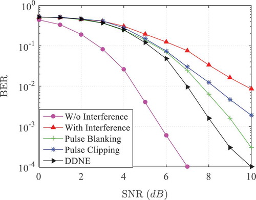
In evaluating the effectiveness of the DDNE approach in the LDACS1 FL system, in Figure , the BER vs. signal-to-noise ratio (SNR) is shown for the proposed system for AWGN channel and compared with the conventional pulse blanking and clipping methods. The simulations are done for LDACS1 FL in a flat fading channel. The main purpose of this simulation to shows the effect of DME interference to LDACS1 receiver at aircraft from a single DME GS that operates in the +0.5 MHz offset to the L-DACS1 FL centre frequency. Figure shows the performance degradation of the LDACS1 system in terms of BER due to the DME interference, it leads to the performance loss of 5dB SNR at 10−2 BER. As can be seen from the figure, the proposed DDNE-based LDACS1 system leads to a SNR performance improvement of about 1 dB for BER 10−3 when compared to the pulse blanking method with and 2dB SNR improvement is observed when compared to the PC method with
.
Figure 7. BER performance of the proposed DDNE, pulse blanking and pulse clipping method as a function of SNR over AWGN channel.
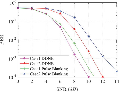
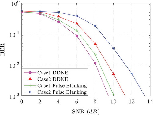
The pulse interference from the DME station has been characterized by considering the total number of interfering DME GS, case1 and case2. For case1, a single DME GS with X mode (Qiu et al., Citation2017), a transmission rate of 3600 ppps, a frequency offset of +0.5 MHz and a peak transmit power of 60 dBm is considered, where case2 consider the two DME GSs with ±0. 5 MHz frequency offset to the LDACS1 FL centre frequency. In Figure , the BER vs SNR of the proposed DDNE and pulse blanking for LDACS1 FL is plotted and compared for case1 and case2, respectively with AWGN channel. The main purpose of this comparison is to show the influence of the DME interference on to the performance of the proposed DDNE LDACS1 system when the number of the interfering DME station is increasing. From this figure, we can observe that the LDACS1 system with case1 is outperforming the LDACS1 system with case2 for both the proposed DDNE and pulse blanking methods. It means the performance of the proposed system degrades when the number of the interfering DME station is increased. The LDACS1 system with case 2.
Figure 8. BER performance of the proposed DDNE and pulse blanking method as a function of SNR for case1 and case 2 over AWGN channel.
In evaluating the effectiveness of the En-Route aeronautical channel in the proposed DDNE approach in the LDACS1 FL system in Figure , the BER vs. SNR is shown for the proposed system for En-Route aeronautical channel and compared with the conventional pulse blanking and clipping methods. In En-Route aeronautical channel, the aircraft is assumed to be cruising at an average speed of about 600 knots True Airspeed (KTAS).The average cell size is around 200NM. The channel is modelled as composed of both LOS and non-LOS path that contains a group of reflected, delayed paths, the value of the delay may vary between 0.2
and 15
. In this simulation, we assumed the following optimal En-Route aeronautical channel parameters (Armstrong & Suraweera, Citation2004):
,
,
,
. It is clear from the figure that a significant performance improvement is achieved by proposed technique as same in Figure . In Figure , the similar comparison of BER vs SNR as in Figure is plotted and compared for case1 and case2, respectively with En-Route aeronautical channel and observed the same result.
Figure 9. BER performance of the proposed DDNE, pulse blanking and pulse clipping method as a function of SNR over En-Route aeronautical channel.
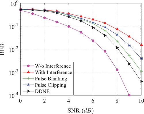
Figure 10. BER performance of the proposed DDNE and pulse blanking method as a function of SNR for case1 and case 2 over En-Route aeronautical channel.
6. Conclusion and future works
In this article, a DDNE approach suitable for mitigating the DME interference in the LDACS1 FL system is proposed. Adapting the aeronautical channel models as described in (Das & Das, Citation2017) is the next important task of this article. The channel model implementation is adapted to fit the OFDMA environment of the LDACS1. Two important steps are involved in the proposed method are an estimation of DME interference component in the received LDACS1 signal based on the preliminary decision made about the transmitted data, then subtraction of the estimated DME interference from the received LDACS1 signal before final LDACS1 decoding section. Numerical results show that the proposed interference mitigation scheme for the LDACS1 achieve superior performance than the conventional pulse blanking and clipping schemes. The proposed approach is analyzed for both the cases of the AWGN and En-Route aeronautical channel. In the future work, the interference mitigation scheme for LDACS1 Reverse Link (RL) with suitable aeronautical channel will be considered. Furthermore the interference mitigation scheme will develop to detect and mitigate the effect of legacy system other than the DME system which already operated on L-band.
Citation information
Cite this article as: Mitigation of DME interference in LDACS1-based future air-to-ground (A/G) communications, Raja Muthalagu, Cogent Food & Agriculture (2018), 5: 00000103.
Additional information
Funding
Notes on contributors

Raja Muthalagu
Raja Muthalagu received his Ph.D. in Wireless Communication from National Institute of Technology (NIT), Tiruchirappalli, India in 2014. He joined the Department of Electrical and Electronics Engineering, BITS, Pilani, Dubai Campus, in 2015, where he is currently a full Assistant Professor. He was a postdoctoral research fellow at ATMRI, Nanyang Technological University (NTU), Singapore, during 2014−15. He was a recipient of Canadian Commonwealth Scholarship Award-2010 for Graduate Student Exchange Program in the Department of Electrical and Computer Engineering, University of Saskatchewan, Saskatoon, SK, Canada and also he is a Visiting Scholar in the Department of Electrical and Computer Engineering, University of Saskatchewan, Saskatoon, SK, Canada during January 2011- June 2012. His research interests include OFDM, MIMO and network security.
References
- Armstrong, J. , & Suraweera, H. A. (2004, August) Impulse noise mitigation for OFDM using decision directed noise estimation. In Proceedings of IEEE ISSSTA 2004 (pp. 784–788. vol. 2). Sydney, Australia.
- Brandes, S. , Epple, U. , & Schnell, M. (2009, November). Compensation of the impact of interference mitigation by pulse blanking in OFDM systems. In Proceedings of the IEEE Global Telecommunications Conference. Honolulu, HI.
- Brandes, S. , & Schnell, M. (2009). Interference mitigation for the future aeronautical communication system in the L-Band In Proceedings 7th International Workshop on Multi-Carrier Systems & Solutions (MC-SS 2009) (pp. 375–384). Herrsching, Germany, Springer.
- Das, D. , & Das, S. (2017). A novel approach for cognitive radio application in 2.4-GHz ISM band. International Journal of Electronics , 104(5), 792–804. doi:10.1080/00207217.2016.1244865
- Epple, U. , & Schnell, M. (2011, October) Overview of interference situation and mitigation techniques for LDACS1. In Proceedings of the Digital Avionics System Conference.
- Epple, U. , & Schnell, M. (2014, Feb). Overview of legacy systems in L-band and its influence on the future aeronautical communication system LDACS1. IEEE Aerospace and Electronic Systems Magazine , 29, 31–37. doi:10.1109/MAES.2014.120092
- Epple, U. , & Schnell, M. (2015, April 21–23). Mitigation of impulsive interference for LDACS1 – potentials of blanking nonlinearity. IEEE ICNS Conference 2015. Washington, DC, USA.
- Epple, U. , Shibli, K. , & Schnell, M. (2011). Investigation of blanking nonlinearity in OFDM systems. In Proceedings of IEEE Internation Communicaiton Conference (pp. 1–5).
- EUROCONTROL . (2007). Framework for spectrum compatibility analysis in L-Band for FCI technology candidates. Draft 1.0.
- EUROCONTROL . (2008). EUROCONTROL’s Challenges of Growth 2008 study report.
- Fistas, N. , & Phillips, B. (2007, October). Future communication study – action plan 17: Final conclusions and recommendations report. Digital Avionics Systems Conference. Dallas.
- Future Communications Study Operational Concepts and Requirements Team . (2007). Communications operating concept and requirements for the future radio system . (Tech. Rep.). EUROCONTROL/FAA.
- Gao, G. X. (2007, September) DME/TACAN interference and its mitigation in L5/E5 bands. ION Institute of Navigation Global Navigation Satellite Systems Conference. Fort Worth, TX, USA.
- Gligorevic, S. , Schneckenburger, N. , Franzen, N. , Schnell, M. , Muller, S. , & Gunzel, H. (2011, October). L-band compatibility of LDACS1. 3rd CEAS Air and Space Conference. Venezia, Italy.
- Gräupl, T. , & Mayr, M. (2015). Method to emulate the L-band digital aeronautical communication system for SESAR evaluation and verification. In Proceedings of the 34th Digital Avionics Systems Conference. Prague, Czech Republic.
- Haas, E. (2002, March). Aeronautical channel modeling. IEEE Transactions on Vehicular Technology , 51(2), 254–264. doi:10.1109/25.994803
- Haring, J. , & Vinck, A. J. H. (2003). Iterative decoding of codes over complex numbers for impulsive noise channels. IEEE Transactions on Information Theory , 49(5), 1251–1260. doi:10.1109/TIT.2003.810636
- Jain, R. , Templin, F. , & Yin, K.-S. (2011, January 1) Analysis of L-band digital aeronautical communication systems: L-DACS1 and L-DACS2. AC paper #1057, Version 2. Updated. Big sky: IEEE.
- Khuwaja, A. A. , Chen, Y. , Zhao, N. , Alouini, M.-S. , & Dobbins, P. (2018). A survey of channel modeling for UAV communications. submitted for publication. Retrieved from https://arxiv.org/abs/1801.07359
- Mostafa, M. , & Schnell, M. (2015, April 21-23). DME-compliant LDACS1 cell planning: Initial steps. 2015 Integrated Communications, Navigation, and Surveillance (ICNS) Conference. USA.
- Mott, J. H. (2018). Estimation of aircraft distances using transponder signal strength information. Cogent Engineering , Accepted manuscript, 1466619. doi:10.1080/23311916.2018.1466619
- Qiu, Z. , Chu, X. , Calvo-Ramirez, C. , Briso, C. , & Yin, X. (2017). Low altitude UAV air-to-ground channel measurement and modeling in semiurban environments. Wireless Communications and Mobile Computing , 2017, 1–11. Article ID 1587412. doi:10.1155/2017/1587412
- Raja, M. , Vinod, A. P. , & Madhukumar, A. S. (2015). DME interference mitigation technique for L-band digital-aeronautical-communications-system1 (LDACS1) based on decision-directed noise estimation approach. Proceedings of Integrated Communications Navigation and Surveillance (ICNS) Conference . Virginia, USA.
- Saaifan, K. A. , Elshahed, A. M. , & Henkel, W. (2017, Dec.). Cancelation of distance measuring equipment interference for aeronautical communications. IEEE Transactions on Aerospace and Electronic Systems , 53(6), 3104–3114. doi:10.1109/TAES.2017.2728958
- Sajatovic, M. , Haindl, B. , Ehammer, M. , Gräupl, T. , Schnell, M. , Epple, U. , & Brandes, S. (2009, February). LDACS1 system definition proposal. Eurocontrol Study, Edition 1.0.
- Schneckenburger, N. , Jost, T. , Shutin, D. , Walter, M. , Thiasiriphet, T. , Schnell, M. , & Fiebig, U.-C. (2016, October). Measurement of the l-band air-to-ground channel for positioning applications. IEEE Transactions on Aerospace and Electronic Systems , 52(5), 2281–2297. doi:10.1109/TAES.2016.150451
- Schnell, M. , Brandes, S. , Gligorevic, S. , Rokitansky, C. H. , Ehammer, M. , & Gräupl, T. (2008a, May). B-AMC- broadband aeronautical multi-carrier communications. In Proceedings of the Integrated Communications Navigation and Surveillance Conference. Bethesda, MD.
- Schnell, M. , Brandes, S. , Gligorevic, S. , Rokitansky, C.-H. , Ehammer, M. , Gräupl, T. , &; Sajatovic, M. (2008b, May) B-AMC broadband aeronautical multi-carrier communications. In Proceedings of the Integrated Communications Navigation and Surveillance Conference. Bethesda, MD.
- Schnell, M. , Epple, U. , Shutin, D. , & Schneckenburger, N. (2014, May). LDACS: Future aeronautical communications for air-traffic management. IEEE Communications Magazine , 52, 104–110. doi:10.1109/MCOM.2014.6815900
- Shan, D. , Richardson, P. , Xiang, W. , Zeng, K. , Qianc, H. , & Addepalli, S. (2014). Time-varying channel estimation through optimal piece-wise time invariant approximation for high-speed train wireless communications. Journal of Vehicular Communications , 1, 67–77. doi:10.1016/j.vehcom.2014.04.003
- Shongwe, T. , Vinck, A. J. H. , & Ferreira, H. C. (2015). A study on impulse noise and its models. SAIEE Africa Research Journal , 106(3), 119–131.
- Thiasiriphet, T. , Schneckenburger, N. , & Schnell, M. (2015, September 14–18). Impact of the DME interference on the LDACS1 ranging performance. ON GNSS+ 2015. Tampa, USA.
- Zhidkov, S. V. (2003). Impulsive noise suppression in OFDM based communication systems. IEEE Transactions on Consumer Electronics , 49(4), 944–948. doi:10.1109/TCE.2003.1261179