
 ?Mathematical formulae have been encoded as MathML and are displayed in this HTML version using MathJax in order to improve their display. Uncheck the box to turn MathJax off. This feature requires Javascript. Click on a formula to zoom.
Abstract
Externally bonded fibre reinforced polymer (FRP) has been proven to be a successful strengthening technique for deteriorated and aged structures. In the last two decades, an extensive number of studies have been dedicated to investigating this strengthening method. Therefore, it is considered to be extremely time-consuming for researchers to go through most of these studies. The aim of this paper is to provide an extensive review of a considerable number of papers in which a special emphasis is placed on the finding of the most recent papers. The paper focuses on the bond behaviour, testing techniques and models used to assess bonding strength. The deterioration of the FRP due to moisture has been also examined. Finally, flexural, shear and fatigue behaviours of this strengthening technique have been intensively reviewed. It was concluded that silane coupling agents can be used to enhance bond characteristics of poorly treated surfaces under moisture effect. It was also found that FRP can be used to extend the fatigue life of concrete beams. Finally, the review also showed that the Pellegrino and Modena model provides a good prediction of the shear strength of FRP-strengthened concrete beams.
PUBLIC INTEREST STATEMENT
Many of the existing infrastructures are close to their designed lifetime. Demolishing them to build new ones is not possible in many cases. Therefore, repairing and strengthening them is a feasible solution. Fibre reinforced polymer (FRP) sheets and laminates are one of the materials used to strengthen and repair these infrastructures. External bonding of FRP is one of the most common methods. Like other methods, this method has pros and cons. The current paper presents some of the laboratory tests used to evaluate this method. In addition, it discusses some of the factors influencing this method. Finally, it compares the models proposed to predict the behaviour of the strengthened and repaired concrete members.
1. Introduction
Strengthening and repairing of the deteriorated concrete members by the method of external bonding has been proven to be a successful technique. Steel plates are widely considered due to their good strength, ductility and the homogeneous properties (Oehlers, Citation1992). However, being exposed to the open environments, steel would suffer from corrosion and then thickness loss. As a result, the cross-sectional area would be reduced, leading to a reduction in the strength of the attached plate. This harmful effect could be avoided by covering the plate by any anti-corrosive material such as asphalt or oil. However, these protection methods could highly increase the cost of the strengthening and maintenance. The lack of the performance of steel plates in a specific environment shifted the interest towards alternative strengthening materials such as carbon fibre reinforced polymer (CFRP), glass FRP (GFRP), aramid FRP (AFRP) and basalt FRP (BFRP). These FRPs can be made into sheets, laminates or rebar.
FRPs are considered as one of the most suitable strengthening materials currently due to their corrosion resistance, high strength-to-weight ratio, high stiffness-to-weight ratio, high energy absorption properties and ease of installation (Aslam, Shafigh, Jumaat, & Shah, Citation2015; Oehlers & Seracino, Citation2004; Teng, Citation2002). Thus, they are used to strengthen old structures such as bridges, where handling arrangement has a significant role. They are also used for seismic upgrade. A study by Pham and Hao (Citation2016) showed that FRP can be used to improve impact resistance by increasing energy absorption and load carrying capacity. Each type of the aforementioned FRPs has its advantages and disadvantages.
AFRP has good corrosion resistance and fatigue properties. However, its poor performance against acids and alkalis shifted the focus towards CFRP. CFRP has higher chemical resistance, higher temperature resistance and higher fatigue resistance in addition to the high strength-to-weight ratio in comparison with other types of FRPs (Li, Guo, & Liu, Citation2008; Wu, Wang, Yu, & Li, Citation2009). These characteristics made CFRP more preferable in the strengthening applications. Nevertheless, CFRP has a low ductility. In order to make good use of the high strength of the CFRPs and good ductility of GFRP, they are used in form of combined layers to strengthen structures (Li et al., Citation2008).
Studies (Aslam et al., Citation2015; Li et al., Citation2008; Oehlers & Seracino, Citation2004; Pham & Hao, Citation0000; Teng, Citation2002; Wu et al., Citation2009) showed that stresses are transferred from concrete to FRP via the bond. Consequently, characteristics of the FRP-to-concrete interface are fundamental to evaluate the behaviour of the concrete strengthened members. In the present work, the testing methods used to evaluate bond strength are discussed and compared to determine the advantages and disadvantages of each method. Then, geometrical factors (FRP-to-concrete width ratio), mechanical factors (concrete compressive strength, adhesive stiffness and others) and environmental factors (moisture, temperature and others) influencing the bond strength are presented and discussed to determine the dominant factors. Models proposed to predict bond strength are also presented with focus on the most accurate one.
The paper also presents a critical review of flexural, shear and fatigue strengths of concrete beams externally bonded with FRPs. It discusses the possible failure modes of the FRP-reinforced beams and the factors influencing these modes. The importance of the current work is derived from the comprehensive review of a large number of studies in which considerable attention is given to the most recent ones. Moreover, it focuses on the recently proposed models and design procedures that give an acceptable prediction for the flexural, shear, and fatigue strengths of the FRP-strengthened concrete beams.
2. Research motivation
An extensive number of studies have been conducted in the last two decades to evaluate the behaviour of the concrete elements strengthened with FRP. Consequently, researchers interested in this topic need great effort and time to go through most of these studies. The purpose of this paper is to provide an extensive review of the work done in this field where a higher consideration is given for the recent finding. It also points to the areas that have not been totally understood and need more investigations.
3. FRP strengthening techniques
There are various strengthening techniques used to retrofit and strengthen deteriorated concrete beams. The most common technique is the externally bonded reinforcement (EBR) (Yao, Teng, & Chen, Citation2005). In this method, the FRP sheet or procured laminate is attached to the tensile surface of the concrete beams using resin. Grinding and smoothing processes of the tensile surface of concrete precede the FRP attachment. Sometimes, a primer would be used to enhance the bond characteristics between the FRP and the concrete surface. Another strengthening technique is the near surface mounted (NSM). In this method, grooves or slots are made on the tensile surface of the concrete beam. Then FRP bars or laminates are inserted inside these grooves and attached using any bonding agent. This technique is more popular to strengthen systems where adding a new layer could affect their performance, such as places of negative moments in continuous bridges. Another strengthening technique reported by other studies is using discrete nail-type anchors without bonding agent (Chahrour & Soudki, Citation2005; Kim & Heffernan, Citation2008). Figure shows the three strengthening techniques. Among the aforementioned strengthening techniques, this paper is dedicated to reviewing EBR in detail.
Figure 1. Strengthening technique (a) EBR (b) NSM and (c) externally bonded using nails (Kim & Heffernan, Citation2008).
4. Bond characteristics of FRP
The bond between FRP and concrete is crucial in transferring stresses from concrete to FRP. Bond failure is the dominant failure form for FRP. Therefore, the bonding strength of the concrete-to-FRP interface is the key factor in evaluating the strength of FRP-strengthened concrete beams. Researchers (Chahrour & Soudki, Citation2005; Kim & Heffernan, Citation2008; Lu, Teng, Ye, & Jiang, Citation2005; Xiong, Jiang, Liu, & Chen, Citation2007; Yao et al., Citation2005) utilized the bond-slip property to estimate the ultimate interface strength. It is important to mention that the term “interface” used in this paper refers to the interfacial part of the FRP-to-concrete joint, including FRP, adhesive and a thin layer of concrete beneath the adhesive.
4.1. Testing techniques
Up to date, there is no consensus on a standardized bond test to investigate parameters affecting the interface strength (Serbescu, Guadagnini, & Pilakoutas, Citation2013). Nonetheless, there have been increasing efforts to defend one of the single-shear test (SST), the double-shear test (DST) or the beam test (BT) as a standard bonding test. However, each one of these has its pros and cons.
4.1.1. Single-shear test
It is called single-shear test because only a specific length of the FRP sheets is going to be attached to the concrete substrate. The rest of the length is free with its end being cripped by the testing machine. This testing technique is also known as a push–pull scheme because the concrete block is under pushing load, while the FRP reinforcement is under pulling force. The test set-up has fewer details than the others, which makes it easier to fabricate and handle. It also provides a less disturbed data. Moreover, it can easily control the angle of the applied load; hence, various loading modes can be introduced (Bencardino, Condello, & Ashour, Citation2017). Therefore, numerous researchers adopted this testing technique to extract bond-slip properties (Ghorbani, Mostofinejad, & Hosseini, Citation2017; Gravina, Aydin, & Visintin, Citation2017; Zhang et al., Citation2017; Zhang, Smith, & Gravina, Citation2016; Zhang, Smith, Gravina, & Wang, Citation2017). However, it failed to simulate the bond-slip behaviour of a real strengthening application (Serbescu et al., Citation2013). Figure shows one of the test configurations utilized by researchers (Bilotta, Di, & Nigro, Citation2011).
Figure 2. Single-shear test (Bilotta et al., Citation2011).
4.1.2. Double-shear test
In this testing technique, both parts of the FRP sheet or plate are attached to two separate concrete blocks. This technique is also known as the pull–pull scheme because both the FRP reinforcement and the concrete block are under tension load. By having both sides attached to separate concrete blocks, this testing technique succeeded in providing a closer representation of a real strengthening situation. However, it failed to mimic the peeling stress developed in flexural members (Serbescu et al., Citation2013). Alternatively, while the double-shear test is capable of simulating peel-off debonding failure induced by interfacial shear stress, it cannot simulate rip-off debonding produced by shear and flexural stresses. Moreover, this technique requires special attention in detailing and handling to ensure consistent results. In other words, the results obtained by this testing technique are sensitive to the geometry and alignment of the concrete block (Bilotta et al., Citation2011). Figure shows some testing set-up (Serbescu et al., Citation2013).
Figure 3. Double-shear test (Serbescu et al., Citation2013).
4.1.3. Beam specimen
The interfacial stresses between FRP reinforcement and the concrete substrate can be best represented by a bending test technique using a beam specimen. However, this specimen is cumbersome to be handled and used as a standard bond-test. In addition, this testing technique could not provide insight into a predetermined failure mode such as intermediate debonding under pulling/peeling effect. Thus, modifications were proposed by Pan and Leung (Pan & Leung, Citation2007) using two blocks. One of them was made of concrete, while the other one was made of steel. The two blocks are attached to each other using a steel hinge from the top. However, the FRP sheet is attached to the bottom surface of the two blocks, as shown in Figure . These modifications made this specimen more complicated and far from being considered as a standard test for in situ situations.
Figure 4. Beam specimen set-up (Pan & Leung, Citation2007).
4.2. Parameters influencing bond strength
Studies (Chahrour & Soudki, Citation2005; Mukhopadhyaya & Swamy, Citation2001; Teng, Citation2002) showed that several parameters control the bond strength of the FRP interface. These parameters are the effective bond length, FRP-to-concrete width ratio, concrete compressive strength, FRP axial stiffness, adhesive stiffness, adhesive strength and concrete surface preparation. Moreover, environmental factors such as moisture, freeze–thaw, temperature and others were proven to have a great influence on bonding strength and durability. Therefore, they attracted the attention of numerous recent studies (Heshmati, Haghani, & Al-Emrani, Citation2015; Shrestha, Ueda, & Zhang, Citation2015).
4.2.1. Effective bond length
Tensile stress is transformed from the FRP sheet to the concrete surface taking the shortest path via direct shear. This stress starts decreasing exponentially as it moves away from the point of the maximum stress to the end of the plate. Thus, the effective bond length can be defined as the minimum length required to transfer the maximum tensile stress from the concrete substrate to the FRP sheet or plate via direct shear. Although it is experimentally difficult to determine the precise bond distribution, the effective bond length can be estimated as the distance from the loaded end to the point where local stress tends to zero (Serbescu et al., Citation2013). It is worthy to mention that the effective bond length is relatively constant with the amount of the applied load. In other words, the bond length required to transfer bond stress does not increase as the applied load increases.
Xiao, Li, and Zha (Citation2004) investigated the effective bond length of the E-glass fibre by placing a number of strain gauges on the top of the FRP surface in the double-shear test. Then, the load was increased gradually. It was observed that strain gauges away from the loaded end did not record any changes in the strain as the load increased, as shown in Figure . A similar conclusion was obtained by Ko, Matthys, Palmieri, and Sato (Citation2014) when they investigated the bond strength of carbon fibre as shown in Figure ). It can also be seen from the same figure that the curvature of the strain profile reverses as the applied load reaches 98% of the ultimate load. This change in the curvature can be attributed to the initiation of debonding.
Figure 5. Strain distribution under various loads (a) GFRP (b) CFEP and (c) GFRP versus CFRP.
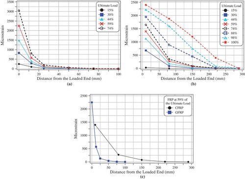
Figure compares between the experimental results of the strain distribution of GFRP and CFRP investigated by Xiao et al. (Citation2004) and Ko et al. (Citation2014), respectively. It can be seen that at 59% of the ultimate load, both curves have similar profiles. However, the strain in the specimens with the CFRP reinforcement was recorded at the longer distance. This can be attributed to the higher axial stuffiness, E f t f, of the carbon fibre. Hence, carbon fibre can have a longer effective bond length than the glass fibre. It is important to note that Ko et al. (Citation2014) recorded strain at 10 mm from the loaded end. Yet, Xiao et al. (Citation2004) recorded it right over the loaded ends. This difference made the initial strain of the GFRP higher than CFRP.
Teng, Smith, Yao, and Chen (Citation2003) proposed the following simplified expression to provide a close estimation of the effective bond length.
Seracino, Raizal Saifulnaz, and Oehlers (Citation2007) proposed the following generic model to determine the effective bond length of both externally bonded FRP and near-surface bonded FRP.
where d fl and b fl are the length of the failure plane perpendicular to the concrete surface (depth in concrete cover) and length of failure plane parallel to the concrete surface, respectively, as shown in Figure .
Figure 6. Failure plane (a) Externally bonded FRP and (b) Near-surface mounted NSM (Seracino et al., Citation2007).
It is already determined that increasing the applied load would crack and weaken the effective bond area. Hence, in order to overcome the excessive load, the bond is shifted to the next area. This shifting in the effective bond zone continues as the load increases until the end of the sheet is reached. Therefore, unlike the internally bonded reinforcement, increasing the anchorage length of externally bonded FRP would not increase its strength. However, it improves the beam ductility.
4.2.2. FRP-to-concrete width ratio and concrete compressive strength
Studies (Bilotta et al., Citation2011; Serbescu et al., Citation2013) showed that the width of FRP and concrete compressive strength directly influence the bond characteristics of the FRP. Thus, analytical relationships considered them among the influential factors. Thomsen, Spacone, Limkatanyu, and Camata (Citation2004) showed that increasing the FRP width would reduce the bonding stresses in the FRP-to-concrete interface, giving a higher flexural strength. Yao et al. (Citation2005) investigated the FRP-to-concrete width ratio (bf/bc ) and the axial stiffness. They concluded that bond strength increases as this ratio approaches 1. Ko et al. (Citation2014) reviewed the factors affecting bond stress–slip behaviour. One of their conclusions is that concrete strength is the dominant factor. Hence, a new model was derived by considering compressive strength only.
4.2.3. Concrete surface preparation
Although international design guidelines such as ACI 440 2R (ACI committee 440, Citation2008) and CNR-DT 200 (CNR, Citation2013) provide general recommendations for the concrete surface preparation, they do not clearly estimate the effect of these preparations on the bond capacity. One of these recommendations is to use high-pressure water jets and grinding to remove the deteriorated concrete layers. Nonetheless, other studies (Al-Tamimi, Ozkul, Azzam, & Sabetnia, Citation2011; Arya, Clarke, Kay, & O'Regan, Citation2001) showed that high-impact preparation such as bush hammering could weaken the surface of the concrete.
It was observed that a rough surface could develop twice the local stress developed in a smooth one. Thus, a coefficient β, which represents the ratio between the maximum achievable bond stress and the concrete shear strength, was introduced by Serbescu et al. (Citation2013) to account for the surface roughness. Test results showed that β ranges from 0.55 for smooth surfaces to 0.85 for rough surfaces. For surfaces that are well prepared and prime-coated, the bond capacity tends to be close to the concrete shear strength, and β becomes 1.
4.2.4. Moisture resistance of FRP
Various environmental conditions can cause premature failure in the structural elements strengthened with FRP. These conditions are moisture, alkali, temperature variation, ultraviolet radiation and others. However, out of all these parameters, moisture is the dominant factor (Karbhari et al., Citation2003; Shrestha et al., Citation2015). Therefore, moisture is the only environmental factor considered in this paper.
Moisture has uneven effects on the consultative materials of the FRP-to-concrete interface. Studies (Benzarti, Freddi, & Frémond, Citation2011; Cabral-Fonseca et al., Citation2018; Maljaee, Ghiassi, Lourenço, & Oliveira, Citation2016) showed that moisture has a slight effect on the compressive strength of the concrete. Regarding the FRP composite, moisture has a degradation effect on the matrix that connects the fibres with each other in the laminate. It also has a damaging effect on fibre made of glass. However, it has a seldom effect on the fibre made of carbon. This finding made some researchers (Ramirez, Carlsson, & Acha, Citation2008; Sethi & Ray, Citation2015) believe that matrix-dominated properties, such as interlinear shear, are expected to be more deteriorated by moisture. Finally, regarding the adhesive, moisture disperses into the organic polymers, leading to mechanical, chemical and thermophysical changes. Studies (Cabral-Fonseca et al., Citation2018; Maljaee, Ghiassi, & Lourenço, Citation2017) showed that moisture can cause reversible changes that vanish after drying, such as plasticization and swelling. Other changes are irreversible such as hydrolysis and cracking. These changes lead to substantial loss of the fracture toughness of the interface. Moreover, it shifts the debonding failure mode from cohesive, positioned within the concrete cover, to the adhesive–concrete substrate (Karbhari & Engineer, Citation1996).
Since the bond between the polymer and the concrete cannot resist water or moisture attack, silane coupling agents are used to improve bonding and residual fracture toughness. Amidi and Wang (Amidi & Wang, Citation2016a) observed that applying silane coupling agent would shift the failure from the adhesive to cohesive within the concrete substrate. In addition to shifting failure type, applying prime silane to the poorly treated concrete surface could enhance the bonding strength of FRP-to-concrete interface (Ye, Friedrich, Weimer, & Mai, Citation1998). However, it did not have any significant effect when it was applied to well-treated concrete surfaces. The silane primer depends on two mechanisms to enhance the durability of the FRP-to-concrete interface. First, it creates a chemical bond between the concrete and the epoxy. This bond is stronger than the hydrogen bond created when only the epoxy primer is used. Second, a hydrophobic organosilicate layer is formed at the surface of the concrete, which reduces the water entry and subsequent hydrolysis.
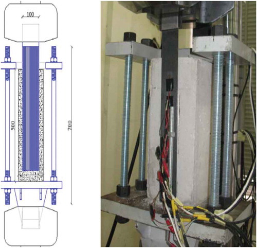
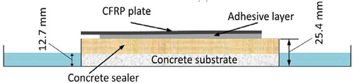
Some studies (Amidi & Wang, Citation2016a; Benzarti, Chataigner, Quiertant, Marty, & Aubagnac, Citation2011) evaluated the strength of the FRP-to-concrete interface before and after exposure to the various environmental conditions using an innovative testing method. In these studies, the reduction in the ultimate strength and failure mode under the effect of the moisture were evaluated using a wedge driving test. Specimens were conditioned either in full immersion in water or half immersion, as shown in Figure . After moisturizing the specimens for the specified period, they were left to dry or tested directly. The reduction in the fractural toughens of the interface was determined by comparing the results of the conditioned specimens with a reference specimen. It is worth mentioning that the purpose of using a half-immersed specimen is to produce uniform moisture distribution along the interface and to prevent fast moisture diffusion through the epoxy-to-concrete interface (Karbhari & Engineer, Citation1996).
Figure 7. Specimen used to determine durability via half immersing (Amidi & Wang, Citation2016a).
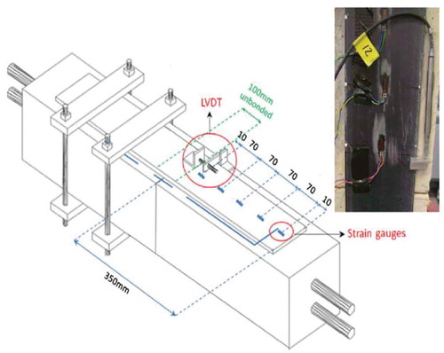
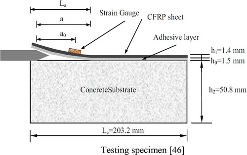
Another study (Zhang, Wang, & Fridley, Citation2012) concluded that debonding failure is the end point of a slow process of a crack growing under the synergic effect of moisture, temperature, loading and other factors. Thus, recent researches focused on the synergic effect of humidity, temperature and static load other than only the loads occurring at the catastrophic failure. In another study (Amidi & Wang, Citation2016b), a predetermined strain was applied to the FRP-to-concrete interface using a steel wedge. The load was limited to the amount in which the debonding due to load was slower than the debonding due to the effect of the environmental factors. In other words, the interface deboning is mainly initiated by environmental factors. This technique is called environment-assisted subcritical debonding (EASD). As shown in Figure , specimens are exposed to these factors by placing them in a chamber that has a specified humidity and temperature. Then crack propagation was monitored using a digital microscope camera and a strain gauge. The strain gauge was used to overcome difficulties due to the bridging effect of the adhesive that makes a measurement with only the camera unreliable sometimes. Then after, the effective crack length was calculated based on the measured strain using the beam theory.
Figure 8. Testing specimen (Amidi & Wang, Citation2016b).
Unlike the traditional subcritical-deboning testing method that reports the degradation in the bonding strength of the FRP-to-concrete composite, the EASD testing reports the effect of the studied factors on the bonding strength. For example, it was reported (Amidi & Wang, Citation2016b) that humidity and temperature accelerate the subcritical deboning. In addition, the failure mode was shifted from adhesive in an aqueous environment to a cohesive one in the ambient environment.
In order to evaluate the effect of the silane treatment, a thin slice of CFRP-to-concrete interface is conditioned in tap water for 7 days. Then, it is examined using a scanning electronic microscope (SEM). The SEM reports mapping images of the studied area, which consists of organic polymer adhesive and inorganic concrete materials. It is important to note that organic materials are mainly built of carbon. Thus, carbon can be utilized to distinguish polymer from concrete. Nevertheless, oxygen is used to identify water distribution in the interface. Figures and 1 show comparisons between two CFRP-to-concrete interfaces studied by Amidi & Wang (Citation2016b). The specimen shown in Figure was not treated using silane treatment. It can be seen that a crack is propagated in the adhesive. However, there is no such crack in the CFRP-to-concrete interface treated with silane, as shown in Figure .
Figure 9. Crack induced in the untreated interface (a) SEM image of the interface soaked in water for 7 days; (b) carbon mapping image; and (c) oxygen mapping image (Amidi & Wang, Citation2016b).
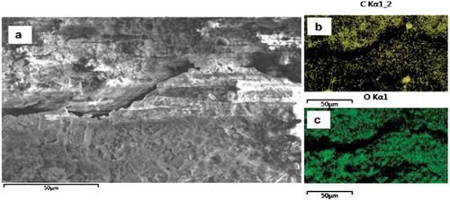
Figure 10. Interface treated with Silane (a) SEM image does not show any crack; (b) carbon mapping image; and (c) oxygen mapping image (Amidi & Wang, Citation2016b).

4.3. Constructing stress–slip curves
The local bond stress–slip property can be determined either by single-shear test or double-shear test (Serbescu et al., Citation2013). Then, the local bond stress–slip curve could be constructed by two methods. The first one depends on the axial strain of the FRP measured using closely spaced strain gauges. Then the slip can be determined by numerical integration, while the shear stress at a particular location of the FRP-to-concrete interface can be estimated using various formulas. Nevertheless, due to the discrete nature of concrete cracks and the heterogeneity of concrete, the measured strain can show significant variation from one place to another, leading to inaccurate local bond-slip curves. In other words, a strain gauge placed over an FRP crossing crack would measure higher strain than the one crossing a big particle of aggregate.
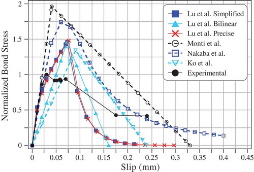
These difficulties in constructing the bond-slip curve directly from the pull tests did not stop researchers (Nakaba, Kanakubo, Furuta, & Yoshizawa, Citation2001; Teng, Yao, & Engineering, Citation2005) from developing a number of bond stress–slip models. Models were utilized to determine tensile capacity in case of bond failure, strain distribution of the FRP, and bond stress distribution. These models are: (a) cut-off type; (b) elastic–plastic type; and (c) tensile softening type, such as bilinear (Ko & Sato, Citation2007; Lorenzis, Miller, & Antonio, Citation2001; Maeda, Asano, Sato, Ueda, & Kakuta, Citation1999). It is important to note that extra care needs to be taken when the cut-off and elastic–plastic types are used because they do not represent a realistic case (Ko et al., Citation2014). The last type consists of an ascending elastic part and a descending plastic part. Figure shows the typical bond-slip models for each of these types. Lu et al. (Citation2005) proposed three models utilizing meso-scale finite element results with appropriate numerical smoothing coupled with test results of 253 pull specimens. Although the precise model proposed by Lu et al. can provide a close estimation of the local bond stress–slip, it is very complicated. Thus, they proposed a simplified one without a significant loss in the accuracy. Nonetheless, Ko et al. (Citation2014) investigated all the factors that influence the bilinear local bond stress–slip model. They concluded that concrete compressive strength is the dominant factor. Based on this finding, they proposed a simpler bilinear local stress–slip model. Figure compares Ko et al.’s and Lu et al.’s models with other models proposed by Nakaba et al. (Citation2001) and Monti, Renzelli, & Luciani (Citation2003) using the following properties: f′c = 30 MPa; ft = 4.2 MPa; bf = 100 mm; b c = 150 mm; E a = 12.8 GPa; G f = 0.45; α 1 = 1.5; α 2 = 0.0195; α 3 = 0.308; K a = 5 GPa; K c = 2.7 GPa. Figure compares the normalized local bond stress–slip curve calculated for one of the tested specimens using closely placed strain gauges with proposed models (Ko et al., Citation2014). It can be noticed that the models overestimate the bond stress. This overestimation may be attributed to the discrete nature of concrete cracks and the heterogeneity of concrete. Moreover, bond stress was calculated in the midpoint between the first and the second strain gauges, which are away from the loaded point.
Figure 11. Bond stress–slip relationships (a) cut-off type; (b) elasto-plastic type; and (c) tensile softening type: bilinear type (left) and Popovics type (right) (Ko et al., Citation2014).
Figure 12. Comparison between proposed local bond stress–slip models.
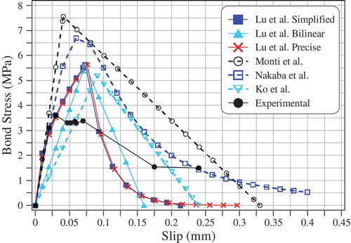
Figure 13. Comparison between normalized local bond stress–slip models and experimental results.
The second method is the indirect method that uses the load-displacement curve to find the bond-slip curve. In this method, a partial-interaction numerical model was adopted to extract bond-slip properties from load-displacement (P-Δ) (Haskett, Oehlers, & Mohamed Ali, Citation2008). A study by Gravina et al. (Citation2017) utilized this method to investigate bond properties of the degraded FRP-to-concrete joint under three immersing conditions. Similar to the first method, it has its own weakness because one load displacement can be constructed from different bond-slip curves (Lu et al., Citation2005). In addition, it cannot be adopted to determine bond-slip for pull test embedment length shorter than the critical length (Haskett et al., Citation2008).
4.4. FRP bond assessment models
Generally, there are two methods to model adhesive joints (Haghani & Al-Emrani, Citation2012), stress/strain-based method and fracture mechanics-based method.
4.4.1. Stress/strain method
An early study (Adams, Comyn, & Wake, Citation1997) proposed to use the average stress distribution along the joint at failure. This method assumes beam members to be rigid. Thus, the adhesive will experience a uniform shear stress. Nevertheless, it ignores the bending effect on the member and the adhesive. Moreover, stress concentration points at joint ends and corners, which normally govern the failure, were also neglected. Another earlier research (Harris & Adams, Citation1984) proposed the usage of the maximum principal stress or strain in the joint where the maximum principal stress exceeds the material’s strength. Since the analytical solution could not be implemented in the points of stress concentration, a numerical solution using the finite element method was utilized (Feldfogel & Rabinovitch, Citation2016; Haghani, Al-Emrani, & Kliger, Citation2009; Liu & Qiao, Citation2017). However, these points are mesh-dependent. Therefore, stress or strain at points away from these points was proposed to be obtained. Based on some studies (Crocombe, Richardson, & Smith, Citation1995; Feldfogel & Rabinovitch, Citation2016; John, Citation1994; John, Kinloch, & Matthews, Citation1991; Liu & Qiao, Citation2017), these points are the finite areas that achieve yielding shear stress.
It is important to point that when it comes to the non-linear behaviour of the materials, the joint’s geometry plays a significant role, which was not considered in the maximum principal stress/strain method (Haghani & Al-Emrani, Citation2012). In other words, the joint must be considered as a whole neither just depending on the material strength obtained from the simple tensile test as in the previous case. Therefore, a study (Achintha & Burgoyne, Citation2008) suggested using the aforementioned representative test techniques such as a single-shear test in conjunction with the maximum principal stress. These tests can provide the failure characteristics of the adhesive joint.
Serbescu et al. (Citation2013) proposed a model to evaluate the maximum force that can be developed before debonding. The proposed model considered most of the factors that can affect the bond strength, such as the average bond stress, effective length, FRP width, concrete strength and surface preparation. The proposed model showed an acceptable degree of accuracy when it was validated against the available database. It also maintained an acceptable level of conservativeness. The proposed model is presented as:
4.4.2. Fracture mechanics-based method
This method depends on the energy that adhesive joint absorbs to fail. There are two procedures to consider this method. The first procedure considers energy as an indicator of failure. Nevertheless, the second procedure considers stress intensity as a failure indicator. Achintha and Burgoyne (Achintha and Burgoyne, Citation2011; Achintha & Burgoyne, Citation2008, Citation2009, Citation2012) utilized the global balance energy method to predict the debonding failure. It was shown that FRP debonding can be considered as a crack that propagates locally by opening in the direction perpendicular to the maximum principal tensile stress (Achintha & Burgoyne, Citation2012, Citation2013).
5. FRP-anchoring systems
Many researchers (Chahrour & Soudki, Citation2005; Xiong et al., Citation2007) attempted to prevent premature failures such as plate-end interfacial debonding, cover separation and intermediate crack (IC). Hence, various forms of anchor systems were proposed (Fu, Teng, Chen, Chen, & Guo, Citation2016; Godat, Ceroni, Chaallal, & Pecce, Citation2017; Zhang et al., Citation2017). One form of anchors investigated by Chahrour and Soudki (Citation2005) consisted of top and bottom 10-mm-thick steel plates, as shown in Figure . The upper and the lower plates were connected using bolts. These end-anchorages were placed at the beam ends to prevent the end-plate failure. It was concluded that the usage of end-anchorages significantly enhanced the flexural performance of beams. Another anchoring system was proposed by another study (Lu et al., Citation2005) to eliminate the end delamination and the IC failure using a U-strip to cover beams along three faces. These U-strips are placed continuously side by side over the longitudinal CFRP sheets or laminates previously attached along the bottom surface of the beams. Carbon fibre sheets could be used as a wrapping material. Nevertheless, the same study recommended using glass fibre instead of carbon fibre in order to reduce the total cost.
Figure 14. Side section for the end anchoring system (Chahrour & Soudki, Citation2005).
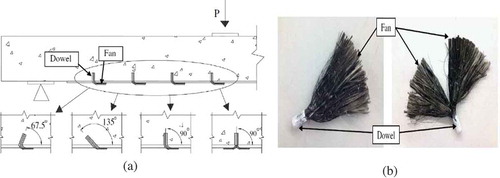
Another research proposed another anchoring technique utilized to delay the FRP debonding and to enhance ductility (Zhang & Smith, Citation2012; Zhang et al., Citation2017). This type of FRP anchor, which is known as spike fibre, consists of two parts, a dowel and a fan. While the dowel is inserted into the concrete member, the fan connects the anchors to the plate as shown in Figure . The total length of anchors is normally 100 mm, where 40 mm is embedded in the concrete holes, which represent the dowels, while the remaining part is attached to the concrete and FRP, which is the fan. It was found that the position of anchors could greatly influence the load carrying capacity and the ductility of concrete members strengthened with FRP. In addition, increasing the inclination angle of the dowel could increase the load carrying capacity as shown in Figure ). However, the ductility of the joint would be decreased as the anchor dowel angle increases. Finally, this type of anchor can be successfully utilized in slabs where it is inapplicable to apply the anchoring system (Smith, Hu, Kim, & Seracino, Citation2011).
Figure 15. Spike fibre (a) concrete strengthened with FRP anchors and (b) FRP anchors (Zhang & Smith, Citation2012; Zhang et al., Citation2017).
6. Serviceability of concrete beams strengthened by FRP
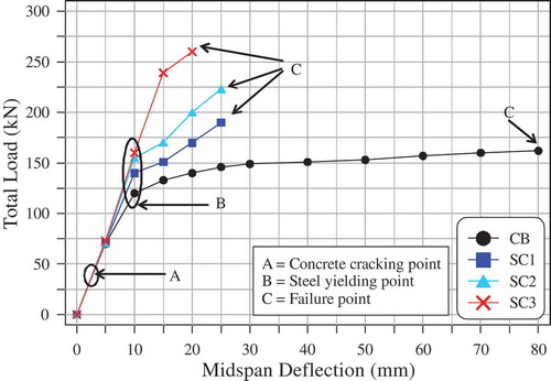
Serviceability of the structural members is generally determined via crack width and deflection. Researchers (Shahawy & Beitelman, Citation1999; Smith et al., Citation2011) concluded that using FRP to strengthen concrete members would increase the stiffness of these members. Thus, the deflection of these members is also going to be reduced. Another study (Maghsoudi & Bengar, Citation2011) observed a positive correlation between the stiffness of the beams and the number of the FRP layers. In other words, there is a reduction in the obtained deflection when the number of FRP layers increases within the same applied load, as shown in Figure . However, strengthening these members shifts the behaviour toward brittleness.
Figure 16. Total applied load versus mid-span deflection (Maghsoudi & Bengar, Citation2011).
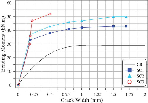
Since using FRP strengthening techniques increases the flexural capacity of concrete beams, it would initiate more cracks, which refers to a better stress redistribution. Maghsoudi and Bengar (Maghsoudi & Bengar, Citation2011) observed that increasing flexural capacity by CFRP would extend the originally generated cracks into the contra flexure region. They also investigated the CFRP influence on crack width of strengthened beams. They concluded that particular crack widths were shifted from steel pre-yielding stage to post-yielding stage. In other words, a smaller crack width was obtained with the same or a higher moment as shown in Figure .
Figure 17. Bending moment versus crack width (Maghsoudi & Bengar, Citation2011).
7. Fatigue behaviour of concrete beams strengthened by FRP
The main problem associated with fatigue is that it may lead to catastrophic failure with a much smaller load than indicated by the static load. Although the behaviour of the strengthened members under monotonic load was the target of most studies, there were a limited number of studies that investigated the behaviour of these members under cyclic loads to determine their fatigue strength. The most common fatigue failure mode observed by the literature (Brena, Benouaich, Kreger, & Wood, Citation2005; Charalambidi, Rousakis, & Karabinis, Citation2016a; Maghsoudi & Bengar, Citation2011; Ntk, Mohammed, & Al-Mahaidi, Citation2017; Peng, Zhang, Shang, Liu, & Cai, Citation2016) is the tensile steel reinforcement rupture followed by FRP failure. Therefore, the fatigue failure of the FRP-strengthened beams is predominantly controlled by the steel reinforcement fatigue life (Charalambidi et al., Citation2016a; Meneghetti, Garcez, Teixeira, & da Silva Filho, Citation2017; Kim & Heffernan, Citation2008). This phenomenon can be easily explained by the fact that steel fails at a stress lower than the failure stress of the FRP. However, the fatigue life of strengthened beams with FRP can be extended by reducing the stresses in the steel reinforcement. It should be noted that fatigue life can be defined as the number of cycles that cause structural system failure.
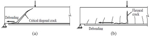
A secondary failure would occur directly after the primary failure, steel rupture, causing the system failure. The most common secondary failure is FRP delamination of the concrete substrate (Kim & Heffernan, Citation2008). Another possible secondary failure is the shear failure induced by diagonal shear cracks. Shear failure is usually obtained in cases where the strengthened beam is subjected to a load that equals the static yield capacity of the strengthened beam. Figure shows the fatigue failure sequence of FRP-strengthened concrete beam (Kim & Heffernan, Citation2008).
Figure 18. Fatigue failure sequence of FRP-strengthened concrete beam (Kim & Heffernan, Citation2008).
Load range is the crucial factor that affects the fatigue life of reinforced concrete beams. Thus, stress range or amplitude is used as an indication of fatigue exposure instead of the applied load level. According to some studies (Charalambidi et al., Citation2016a; Meneghetti et al., Citation2017; Shahawy & Beitelman, Citation1999), increasing the stress range, S a, would decrease the fatigue life of FRP-strengthened concrete beams.
In order to extend the fatigue life of reinforced concrete beams, ACI committee 215 (American Concrete Institute Committee 215, Citation1997) and the AASHTO specifications (American Association of State Highway and Transportation O, Citation2004) recommended maximum stress ranges. These recommendations could be also extended for FRP-strengthened beams as long as the fatigue failure of these beams is steel reinforcement rupture (Brena et al., Citation2005).
Daud, Cunningham, and Wang (Citation2015) investigated the influence of both CFRP stiffness and load range on the fatigue behaviour of FRP-reinforced concrete beams. In their study, a single pull-out shear test was implemented. Various CFRP types and thicknesses were used to obtain different ranges of stiffness. In addition, a fatigue loading at a frequency of 1 Hz with loads ranging from 15% to 70% and 15% to 80% of the ultimate load were examined. The bond-slip relationship was used to describe the bond between CFRP and concrete. It was observed that the ultimate slip of the CFRP was reduced due to cyclic load in comparison with the monotonic load. Moreover, a steady reduction in the bond secant stiffness (upper load versus slip) within every cycle was recorded. It is worth mentioning that the reduction was more obvious in case of higher CFRP thicknesses. In other words, a CFRP with a lower thickness could have a lower fatigue life. The load amplitude range also has a significant effect on the fatigue life. It was also concluded that higher amplitude range would reduce the fatigue life.
The post-fatigue test using monotonic load showed an obvious absence in the ultimate load capacity. This absence ranged from 13.3% for the 0.2-mm thickness to 27.5% for 1.0 mm. This finding does not agree with the conclusion of other studies (Ekenel, Rizzo, Myers, & Nanni, Citation2005; Toutanji, Zhao, Deng, Zhang, & Balaguru, Citation2006) that used a monotonic load after 2 × 10⁶ cycles. In these studies, a reduction of less than 10% was observed in the ultimate load capacity. This lower reduction was obtained because the applied load was within the service limit and accumulated a small fatigue damage influencing the ultimate load. The debonding strain was also reduced from 5.6% for the 0.2-mm thickness to 35% for 1.0 mm. It was also concluded in this research that the concrete compressive strength has a small effect on the ultimate bond strength and the degradation of the fracture energy. However, bond degradation was controlled by CFRP stiffness.
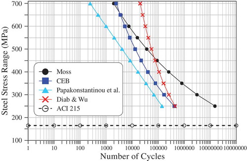
Based on the literature (Diab & Wu, Citation2008; Ekenel et al., Citation2005; Papakonstantinou, Petrou, & Harries, Citation2001; Shahrooz, Citation2011), any model that aims to predict the fatigue performance of FRP-strengthened concrete beams should take into account the stress range of the applied load. Figure shows the relation between the number of cycles and the steel stress range proposed by these studies. Diab and Wu (Citation2008) proposed a regression curve based on the results of FRP-strengthened beams failed in fatigue.
Figure 19. Relation between number of loading cycles and steel stress range.
Since the yielding strength of the reinforcing bar directly affects the fatigue failure of the FRP-strengthened beams, a study by Charalambidi, Rousakis, and Karabinis (Citation2016b) substituted the stress range, σ r, with the ratio of the maximum steel stress to the steel yielding strength, σ max /f y. Moreover, it incorporated the effect of the FRP stiffness using the ratio of the axial tensile rigidity of the tensile steel reinforcement to the tensile rigidity of the FRP, k s /k f. In their study, three models were proposed for three ranges of σ max/f y based on a regression analysis of the available up-to-date data.
8. Flexural strength
FRP laminates or wet lay-up sheets are attached to the tension surface of beams to increase their flexural strength, delay cracks, and reduce crack width (Kim & Heffernan, Citation2008).
8.1. Failure mode
The flexural failure of FRP concrete beams can be classified into two types based on the status of the composite action between the materials (Sayed-Ahmed, Bakay, & Shrive, Citation2009). The first type of failure can take one of three modes: (a) concrete crushing prior to or after steel reinforcement yielding; (b) FRP rupture in the tensile surface; and (c) shear failure of concrete. These modes of failure are rarely to occur because they require to maintain a composite action up to the ultimate load, keeping in mind that the domination of one mode over the others depends on the reinforcement ratio and shear strength.
The second type of failure is the debonding induced in the FRP interface (Sayed-Ahmed et al., Citation2009). This type is the most common failure because it is mostly developed earlier than the first one. Despite the fact that debonding failure can occur in various modes, there are two basic modes that all the other debonding failure modes are derived from (Teng et al., Citation2005). The first mode is the plate-end debonding or delamination, which is characterized by the intersecting of the inclined shear crack with FRP end, leading to its delamination as shown in Figure ). In some cases, this mode is combined by the concrete cover separation at the plate end. In order to prevent the initiation of this failure mode, FRP plates should be extended close to the supports or anchors could be used (Maeda et al., Citation1999).
Figure 20. Debonding failure types (a) plate-end debonding and (b) intermediate crack (IC) (Yao et al., Citation2005).
Using anchors or other methods to avoid plate-end or edge debonding would stimulate another bonding failure known as IC debonding, which is the most common debonding failure. It is induced in the middle of the beam at the location of the flexural or shear/flexure crack as shown in Figure ). Then, it propagates towards the supports. This deboning failure depends on the interface shear between FRP and the adjacent concrete.
8.2. Effective parameters on flexural strength
Studies identified numerous parameters that favour a specific failure mode over another. These parameters could also significantly influence the flexural strength of FRP–concrete beams. The first parameter is the plate or sheet thickness. Rahimi and Hutchinson (Citation2001) concluded that increasing plate and laminate thickness would shift the failure mode from FRP rupture to plate-end debonding. Increasing the plate thickness would also increase the flexural strength. External anchorage is another parameter that could be used to prevent and delay the bonding failure. Sebastian (Citation2001) investigated the plate stiffness effect. He concluded that using stiff plates would dominate the end-debonding failure over the IC failure. Longitudinal reinforcement ratio is another factor affecting the flexural strength of FRP concrete beams. Over reinforced concrete beam would induce a smaller deflection, leading to a less activation of the composite action of FRP. Such a beam is expected to fail in concrete compression crashing combined with visible shear cracks. It would also show a higher flexural strength. Conversely, a lower-reinforced beam would experience laminate deboning failure (Sayed-Ahmed et al., Citation2009). From another study (Rahimi & Hutchinson, Citation2001) that investigated the plate length, it was concluded that extending the plate or the laminate up to the support would delay or avoid end-debonding failure and would also slightly increase the load carrying capacity. A similar result could be obtained using sandblasting surface preparation (Arduini & Nanni, Citation1997). Other parameters that could also influence the mode of failure are prestressing, shear stiffness, laminate orientation and preloading of the beam prior to the FRP application. These parameters were investigated by El-Hacha, Wight, and Green (Citation2001), Triantafillou and Plevris (Citation1992) and Sayed-Ahmed et al. (Citation2009).
8.3. Flexural design
It is already established that IC debonding is the key factor that controls the flexural strength of concrete beams externally strengthened by FRP. Therefore, international design guidelines such as ACI 440 2R (ACI committee 440, Citation2008), CNR DT-200 (CNR, Citation2013) and fib Bulletin n.14 (Externally Bonded, Citation2001) recommend the limiting of the design strain.
ACI 440 2R (ACI committee 440, Citation2008) requires the limiting of the strain, ε f, for FRP reinforcement to be smaller than the strain that develops IC debonding. The limiting strain depends on the composite stiffness and can be calculated by multiplying Young’s modulus, E frp, by the FRP reinforcement thickness, tf rp. CNR DT-200 (CNR, Citation2013) offers a simplified procedure to determine the flexural strength of FRP-strengthened beams by computing the maximum strains in the composite and comparing them with code-proposed strain limitations.
Three design methods are proposed by the fib Bulletin n.14 (Externally Bonded, Citation2001). Similar to the other two aforementioned design guidelines, the first method proposed limiting the tensile strain of the laminate, ε frp, ranging from 0.0065 to 0.0085, in order to prevent laminate peeling-off. The second method depends on a model developed by Niedermeier (Citation2000). This model computes the maximum allowable increase in the tensile stress between two adjacent cracks. This value is then compared with the actual increase obtained for a given load level. The repetitions are then performed on the load level to make the values concurrent. The third method introduces limitations on the shear stress, τ bc, of the concrete-to-FRP interface resulting from the change of the tensile force along the FRP.
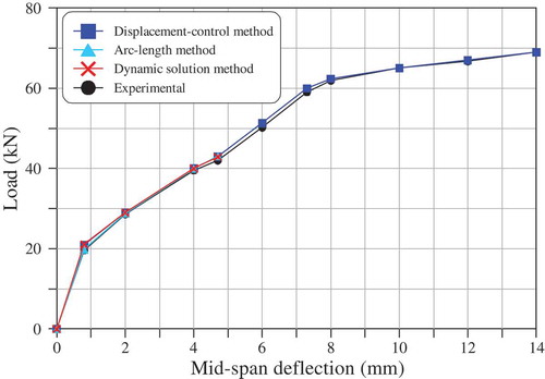
Recent design approaches were proposed by researchers such as Chen et al. (Citation2015) and Oehlers, Visintin, and Lucas (Citation2015). Chen et al. (Citation2015) proposed a dynamic approach to cope with the convergence difficulties in simulating debonding failure of FRP-strengthened beams. In their study, the HHT-α was adopted as a numerical solution to determine the structural response of the FRP-strengthened concrete beam under static/quasi-static loading. Figure compares the numerical prediction of a dynamic approach with test results and shows the numerical predictions by displacement-control method (Newton–Raphson method) and the arc-length method. It can be seen that the dynamic approach can accurately predict the load-deflection response of the beam. However, the other two methods could only predict the deflection up to 4.7 mm.
Figure 21. Numerical prediction versus test results (ζ = 0.005, t0/T1 = 10 for dumping solutions) (Chen, Teng, Chen, & Xiao, Citation2015).
Oehlers et al. (Citation2015) proposed a comprehensive displacement-based approach to design FRP-strengthened concrete beams in which the unbonded FRP is considered to be the prestressing tendon having equal force to that of the IC debonding. Based on this design approach, there are three fundamental modes that could possibly be designed for. Designing for the first mode will ensure that no IC will be developed. Therefore, the IC resistance of the FRP (P IC) should be higher than the expected moment. In addition, the strain developed in the FRP will be lower than the strain required to develop an IC (ε IC). The second mode considers the debonding of part of the bonded FRP because the applied moment will exceed the IC resistance of the FRP. Debonding is expected to be developed at the region of maximum moment, where the IC is expected to be initiated. Nonetheless, the other FRP parts, which lie away from the region of the maximum moment, will keep bonded to the concrete surface. IC resistance and strain in the FRP for this mode exceed (P IC) and (εIC ), respectively. Mode three assumes the debonding of the entire FRP in mode two except the anchored ends. It is worthy to note that this design approach has not been validated with test results, which could be a possible research area.
9. Shear strength
Unlike the flexural behaviour, there are a limited number of studies that have investigated the shear behaviour. These studies showed a desirable enhancement in shear capacity due to an increase in the axial rigidity of the beams (Foster, Morley, & Lees, Citation2016; Hanoon, Jaafar, Al Zaidee, Hejazi, & Aziz, Citation2017; Hanoon, Jaafar, Hejazi, & Aziz, Citation2017; Mostofinejad & Tabatabaei Kashani, Citation2013). Mostofinejad and Kashani (Citation2013) also concluded that further improvement in the shear strength up to 23% could be obtained by grooving the concrete surface beneath the attached CFRP. This extra improvement in shear strength can be attributed to the stronger bond created by the grooves. Similar to the concrete beams reinforced with stirrups to resist shear stresses, the shear strength of the FRP-strengthened beam is a function of the concrete compressive strength and the distance between the adjacent strips.
International design guidelines and several studies proposed models to assess the FRP contribution to shear resistance of externally bonded FRP. These models assume that the nominal shear strength of the externally bonded FRP has even contribution from concrete, V c, steel stirrups, V s, and FRP, V f.
This assumption has been the core of controversy among researchers for a number of reasons. The first reason is that the maximum shear resistance contributed by steel stirrups and FRP may not be reached simultaneously (Chen, Teng, Chen, & Rosenboom, Citation2010). Thus, the summation of their peak contributions could be less than their actual contributions. The second reason is that the contribution of FRP is significantly affected by the shear reinforcement amount. In other words, the efficiency of the FRP strengthening technique seems to decrease as the axial rigidity ratio increases between the internal shear reinforcement and the external FRP shear reinforcement (Pellegrino & Modena, Citation2002, Citation2006, Citation2008). Finally, some of these guidelines use the conventional 45° truss model to calibrate the effective FRP strain model. Thus, for these reasons, some of these models failed to give an accurate estimation of the shear strength of externally bonded FRP.
It has already been stated that design guidelines simply add the contribution of FRP to the contributions of steel and concrete. Thus, these guidelines neglected the interaction between the internal steel stirrups and the external FRP. This interaction can greatly influence the shear strengthening technique and consequently can affect the overall shear strength prediction. Pellegrino and Modena (Citation2008) investigated this interaction. They proposed a model based on experimental observations of shear failure of U-wrapped and side-bonded FRP-strengthened beams. These beams were failed by peeling-off the triangular portion of FRP lying above the diagonal crack in the case of U-wrap, while in the case of side-bonded, the failure was by peeling-of the triangular portion of FRP lying below the diagonal crack. FRP strains were assumed to be equal to the strains in the internal stirrups. Then, FRP contribution was obtained by the rotational equilibrium of the forces F f and F c in the FRP and concrete surface, respectively, as shown in Figure .
Figure 22. Force acting on FRP and concrete surface (a) U-wrapped FRP and (b) side-bonded (Pellegrino & Modena, Citation2008).
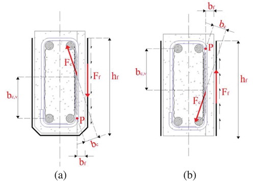
where bc,v and bf are explained in Figure .
The study limited the maximum stress in the internal stirrups to the yielding value if the effective FRP strain is higher than the steel yield stress. Therefore, stirrup contribution to the shear strength of the FRP shear-strengthened beam is:
Pellegrino and Vasic (Citation2013) reviewed some common models (Bukhari, Vollum, Ahmad, & Sagaseta, Citation2010; Carolin & Täljsten, Citation2005; Chen & Teng, Citation2003; Mofidi & Chaallal, Citation2010) proposed to predict the shear capacity of reinforced concrete beams strengthened with FRP. This review also covered the provisions of some design codes like fib-TG 9.3 (Externally Bonded, Citation2001), CNR-DT200 (CNR-DT 200, Citation2004) and ACI 440.2R (ACI committee 440, Citation2008). The influence of the shear crack angle θ was also investigated since it has a significant impact on model prediction. It was concluded that CNR-DT200 (CNR, Citation2013) and Pellegrino and Modena models (Pellegrino & Modena, Citation2008) give good prediction for the most studied cases.
10. Conclusions
This paper presents a critical literature review on the bond, flexural and shear behaviours of concrete beams strengthened with FRP. In addition, different codes and design formulas were reviewed. Fatigue and moisture characteristics were also closely examined. Several critical parameters influencing the aforementioned behaviours were reviewed. Moreover, testing techniques utilized to study the effect of these parameters were presented and discussed. The following conclusions were implied based on the review of this study,
The effective bond length is a crucial parameter for practical design. Seracino et al. (Citation2007) proposed a generic model to assess the effective bond length of both externally bonded FRP and NSM FRP using monotonic load. However, more tests are required to investigate this property under cyclic loading.
Many studies in the literature showed that numerous environmental factors affect the bond strength of FRP-strengthened beams. Nevertheless, moisture is considered as the most influencing environmental factor.
Silane coupling agent can shift the failure mode from the adhesive to cohesive within the concrete substrate. In addition to shifting failure type, applying prime silane to the poorly treated concrete surface can enhance the bonding strength of FRP-to-concrete interface.
Several bond-slip models proposed by researchers were compared in this study against the experimental records. Within the limits of the included parameters, Lu et al. (Citation2005) models were found to simulate the bond-slip behaviour more accurately than others, yet with various degrees of complexity for each model.
The bond model proposed by Serbescuet et al. (2013) provides a good prediction of the maximum tensile force developed in the FRP up to debonding failure because it considers most of the factors affecting bond strength.
More experimental studies are required to extend the current understanding about parameters influencing fatigue behaviour of reinforced concrete beams strengthened with FRP. In particular, f y, as a crucial factor for fatigue design, must be more refined to better include the difference post-yieldingaction of the steel, based on the characteristics of its yielding plateau and of its hardening modulus.
Displacement-based approach proposed by Oehlers et al (Citation2015) can be used to design RC beams strengthened with FRP to achieve higher strength than the beams designed based on strain-based moment curvature. Therefore, this design approach can be more effective.
Pellegrino and Modena (Citation2008) model provides a good prediction of the shear capacity of reinforced concrete beams strengthened with FRP because it considers the interaction between the internal steel stirrups and the external FRP.
Additional information
Funding
Notes on contributors
Sallal R. Abid
Sallal R. Abid is currently a professor at the civil engineering department in the Wasit University/Iraq. He has a Ph.D. degree in civil/structural engineering. The author has many published research works on the thermal analysis of bridge girders and he is also interested in the evaluation of the residual strength of concrete structures and structural members after fire exposure. He has published some articles on the abrasion erosion of cementitious composites and self-compacting concrete in hydraulic structures. The author has also published some papers on fibrous concrete, punching shear strength of flat plates and shear transfer strength.
Karrar Al-lami
Karrar Al-Lami is a lecturer assistant at the College of Engineering of Wasit University. His specialized field of study is civil/structural engineering and composite materials. He finished his master’s degree from Portland State University in the United States and is currently pursuing his Ph.D. degree at the university of Polytechnic of Milan in Italy.
Related Research Data
References
- Achintha, M. , & Burgoyne, C. (2013). Fracture energy of the concrete-FRP interface in strengthened beams. Engineering Fracture Mechanics , 110, 38–51. doi:10.1016/j.engfracmech.2013.07.016
- Achintha, M. , & Burgoyne, C. J. (2011). Fracture mechanics of plate debonding: Validation against experiment. Construction and Building Materials , 25(6), 2961–2971. doi:10.1016/j.conbuildmat.2010.11.103
- Achintha, M. , & Burgoyne, C. J. (2012). Prediction of FRP debonding using the global-energy-balance approach. Magazine of Concrete Research , 64(11), 1033–1044. doi:10.1680/macr.11.00182
- Achintha, P. M. M. , & Burgoyne, C. J. (2008). Fracture mechanics of plate debonding. Journal of Composites for Construction , 12(4), 396–404. doi:10.1061/(ASCE)1090-0268(2008)12:4(396)
- Achintha, P. M. M. , & Burgoyne, C. J. (2009). Moment-curvature and strain energy of beams with external fiber-reinforced polymer reinforcement. ACI Structureal Journal , 106(1), 20.
- ACI committee 440 . (2008). Guide for the design and construction of externally bonded FRP systems for strengthening existing structures . Michigan, MI: American Concrete Institute.
- Adams, R. D. , Comyn, J. , & Wake, W. C. (1997). Structural adhesive joints in engineering. Springer Science & Business Media, 49, 6221.
- Al-Tamimi, A. , Ozkul, T. , Azzam, M. , & Sabetnia, M. (2011). Investigation of the effect of surface preparation method and the degree of surface roughness on CFRP-concrete bonding and substrate strength. Built Human Environment Reviews , 4, 33–44.
- American Association of State Highway and Transportation O . (2004). Bridge design specifications (SI units) (3rd ed.). Wahingston, D.C.: AASHTO LRFD.
- American Concrete Institute Committee 215 . (1997). Considerations for design of concrete structures subjected to fatigue loading . ACI 215R-74 (reapproved 1997). Farmington Hills, Michigan: ACI.
- Amidi, S. , & Wang, J. (2016a). Deterioration of the FRP-to-concrete interface subject to moisture ingress: Effects of conditioning methods and silane treatment. Composite Structures , 153, 380–391. doi:10.1016/j.compstruct.2016.06.035
- Amidi, S. , & Wang, J. (2016b). Subcritical debonding of FRP-to-concrete bonded interface under synergistic effect of load, moisture, and temperature. Mechanics of Materials , 92, 80–93. doi:10.1016/j.mechmat.2015.09.001
- Arduini, M. , & Nanni, A. (1997). Behavior of precracked RC beams strengthened with carbon FRP sheets. Journal of Composites for Construction , 1(2), 63–70. doi:10.1061/(ASCE)1090-0268(1997)1:2(63)
- Arya, C. , Clarke, J,L., Kay, E. A., & O'Regan, P. D. (2001). TR 55: Design guidance for strengthening concrete structures using fibre composite materials-a review. In International Conference on Structural Engineering, Mechanics and Computation, South Africa, Cape Town, pp. 1243–1250. Netherlands, Amsterdam: Elsevier Science.
- Aslam, M. , Shafigh, P. , Jumaat, M. Z. , & Shah, S. N. R. (2015). Strengthening of RC beams using prestressed fiber reinforced polymers - A review. Construction and Building Materials , 82, 235–256. doi:10.1016/j.conbuildmat.2015.02.051
- Bencardino, F. , Condello, A. , & Ashour, A. F. (2017). Single-lap shear bond tests on steel reinforced geopolymeric matrix-concrete joints. Composites Part B: Engineering , 110, 62–71. doi:10.1016/j.compositesb.2016.11.005
- Benzarti, K. , Chataigner, S. , Quiertant, M. , Marty, C. , & Aubagnac, C. (2011). Accelerated ageing behaviour of the adhesive bond between concrete specimens and CFRP overlays. Construction and Building Materials , 25(2), 523–538. doi:10.1016/j.conbuildmat.2010.08.003
- Benzarti, K. , Freddi, F. , & Frémond, M. (2011). A damage model to predict the durability of bonded assemblies. Part I: Debonding behavior of FRP strengthened concrete structures. Construction and Building Materials , 25(2), 547–555. doi:10.1016/j.conbuildmat.2009.10.018
- Bilotta, A. , Di, L. M. , & Nigro, E. (2011). FRP-to-concrete interface debonding: Experimental calibration of a capacity model. Composites Part B: Engineering , 42(6), 1539–1553. doi:10.1016/j.compositesb.2011.04.016
- Brena, S. F. , Benouaich, M. A. , Kreger, M. E. , & Wood, S. L. (2005). Fatigue tests of reinforced concrete beams strengthened using carbon fiber-reinforced polymer composites. ACI Structureal Journal , 102(2), 305.
- Bukhari, I. A. , Vollum, R. L. , Ahmad, S. , & Sagaseta, J. (2010). Shear strengthening of reinforced concrete beams with CFRP. Magazine of Concrete Research , 62(1), 65–77. doi:10.1680/macr.2008.62.1.65
- Cabral-Fonseca, S. , Correia, J. R. , Custódio, J. , Silva, H. M. , Machado, A. M. , & Sousa, J. (2018). Durability of FRP - concrete bonded joints in structural rehabilitation: A review. International Journal of Adhesion and Adhesives , 83(March), 153–167. doi:10.1016/j.ijadhadh.2018.02.014
- Carolin, A. , & Täljsten, B. (2005). Theoretical study of strengthening for increased shear bearing capacity. Journal of Composites for Construction , 9(6), 497–506. doi:10.1061/(ASCE)1090-0268(2005)9:6(497)
- Chahrour, A. , & Soudki, K. (2005). Flexural response of reinforced concrete beams strengthened with end-anchored partially bonded carbon fiber-reinforced polymer strips. Journal of Composites for Construction , 9(2), 170–177. doi:10.1061/(ASCE)1090-0268(2005)9:2(170)
- Charalambidi, B. G. , Rousakis, T. C. , & Karabinis, A. I. (2016a). Fatigue behavior of large-scale reinforced concrete beams strengthened in flexure with fiber-reinforced polymer laminates. Composites Part B: Engineering , 96, 69–78. doi:10.1016/j.compositesb.2016.04.014
- Charalambidi, B. G. , Rousakis, T. C. , & Karabinis, A. I. (2016b). Analysis of the fatigue behavior of reinforced concrete beams strengthened in flexure with fiber reinforced polymer laminates. Composites Part B: Engineering , 96, 69–78. doi:10.1016/j.compositesb.2016.04.014
- Chen, G. M. , Teng, J. G. , Chen, J. F. , & Rosenboom, O. A. (2010). Interaction between steel stirrups and shear-strengthening FRP strips in RC beams. Journal of Composites for Construction , 14(5), 498–509. doi:10.1061/(ASCE)CC.1943-5614.0000120
- Chen, G. M. , Teng, J. G. , Chen, J. F. , & Xiao, Q. G. (2015). Finite element modeling of debonding failures in FRP-strengthened RC beams: A dynamic approach. Computers & Structures , 158, 167–183. doi:10.1016/j.compstruc.2015.05.023
- Chen, J. F. , & Teng, J. G. (2003). Shear capacity of FRP-strengthened RC beams: FRP debonding. Construction and Building Materials , 17(1), 27–41. doi:10.1016/S0950-0618(02)00091-0
- CNR . (2013). Guide for the design and construction of externally bonded FRP systems for strengthening existing structures (CNR - Advis Comm Tech Recomm Constr CNR-DT 200 R1/2013). 154. Rome: Consiglio Nazionale delle Ricerche (The National Research Council).
- CNR-DT 200 . (2004). Guide for the design and construction of externally bonded FRP systems for strengthening concrete structures . Rome: Consiglio Nazionale delle Ricerche (The National Research Council).
- Crocombe, A. D. , Richardson, G. , & Smith, P. A. (1995). A unified approach for predicting the strength of cracked and non-cracked adhesive joints. The Journal of Adhesion , 49(3–4), 211–244. doi:10.1080/00218469508014357
- Daud, R. A. , Cunningham, L. S. , & Wang, Y. C. (2015). Static and fatigue behaviour of the bond interface between concrete and externally bonded CFRP in single shear. Engineering Structures , 97, 54–67. doi:10.1016/j.engstruct.2015.03.068
- Diab, H. , & Wu, Z. S. (2008). Review of existing fatigue results of beams externally strengthened with FRP laminates . Proceedings of the 4th International Conference on FRP Composites in Civil Engineering (CICE2008). Switzerland: EMPA
- Ekenel, M. , Rizzo, A. , Myers, J. J. , & Nanni, A. (2005). Effect of fatigue loading on flexural performance of reinforced concrete beams strengthened with FRP fabric and pre-cured laminate systems. Third International Conference on Composites in Construction , 2005, 405–412.
- El-Hacha, R. , Wight, R. , & Green, M. (2001). Prestressed fibre-reinforced polymer laminates for strengthening structures. Progress in Structural Engineering and Materials , 3(2), 111–121. doi:10.1002/(ISSN)1528-2716
- Externally Bonded, F. R. P. (2001). Reinforcement for RC structures. Fib Bull , (14), 51–58.
- Feldfogel, S. , & Rabinovitch, O. (2016). International journal of mechanical sciences full scale analysis of FRP strengthened plates with irregular layouts. International Journal of Mechanical Sciences , 113, 239–259. doi:10.1016/j.ijmecsci.2016.04.012
- Foster, R. M. , Morley, C. T. , & Lees, J. M. (2016). Modified push-off testing of an inclined shear plane in reinforced concrete strengthened with CFRP fabric. Journal of Composites for Construction , 20(3), 1–10. doi:10.1061/(ASCE)CC.1943-5614.0000623
- Fu, B. , Teng, J. G. , Chen, J. F., Chen, G. M., & Guo, Y. C. (2016). Concrete cover separation in FRP-plated RC beams : Mitigation using FRP U-jackets. Journal of Composites for Construction , 21(2), 1-13.
- Ghorbani, M. , Mostofinejad, D. , & Hosseini, A. (2017). Experimental investigation into bond behavior of FRP-to-concrete under mixed-mode I/II loading. Construction and Building Materials , 132, 303–312. doi:10.1016/j.conbuildmat.2016.11.057
- Godat, A. , Ceroni, F. , Chaallal, O. , & Pecce, M. (2017). Evaluation of frp-to-concrete anchored joints designed for frp shear-strengthened RC T-BEAMS. Composite Structures , 176, 481–495. doi:10.1016/j.compstruct.2017.04.035
- Gravina, R. J. , Aydin, H. , & Visintin, P. (2017). Extraction and analysis of bond-slip characteristics in deteriorated FRP-to-concrete joints using a mechanics-based approach. Journal of Materials in Civil Engineering , 29, 6. doi:10.1061/(ASCE)MT.1943-5533.0001881
- Haghani, R. , & Al-Emrani, M. (2012). A new design model for adhesive joints used to bond FRP laminates to steel beams - Part A: Background and theory. Construction and Building Materials , 34, 486–493. doi:10.1016/j.conbuildmat.2012.02.051
- Haghani, R. , Al-Emrani, M. , & Kliger, R. (2009). Interfacial stress analysis of geometrically modified adhesive joints in steel beams strengthened with FRP laminates. Construction and Building Materials , 23(3), 1413–1422. doi:10.1016/j.conbuildmat.2008.07.013
- Hanoon, A. N. , Jaafar, M. S. , Al Zaidee, S. R. , Hejazi, F. , & Aziz, F. N. A. A. (2017). Effectiveness factor of the strut-and-tie model for reinforced concrete deep beams strengthened with CFRP sheet. Journal of Building Engineering , 12, 8–16. doi:10.1016/j.jobe.2017.05.001
- Hanoon, A. N. , Jaafar, M. S. , Hejazi, F. , & Aziz, F. N. A. A. (2017). Strut-and-tie model for externally bonded CFRP-strengthened reinforced concrete deep beams based on particle swarm optimization algorithm: CFRP debonding and rupture. Construction and Building Materials , 147, 428–447. doi:10.1016/j.conbuildmat.2017.04.094
- Harris, J. A. , & Adams, R. A. (1984). Strength prediction of bonded single lap joints by non-linear finite element methods. International Journal of Adhesion and Adhesives , 4(2), 65–78. doi:10.1016/0143-7496(84)90103-9
- Haskett, M. , Oehlers, D. J. , & Mohamed Ali, M. S. (2008). Local and global bond characteristics of steel reinforcing bars. Engineering Structures , 30(2), 376–383. doi:10.1016/j.engstruct.2007.04.007
- Heshmati, M. , Haghani, R. , & Al-Emrani, M. (2015). Environmental durability of adhesively bonded FRP/steel joints in civil engineering applications: State of the art. Composites Part B: Engineering , 81, 259–275. doi:10.1016/j.compositesb.2015.07.014
- John, S. J. (1994).Predicting the strength of bonded carbon fibre/epoxy composite joints. In Composites bonding . ASTM International. Philadelphia: American Society for Testing and Materials.
- John, S. J. , Kinloch, A. J. , & Matthews, F. L. (1991). Measuring and predicting the durability of bonded carbon fibre/epoxy composite joints. Composites , 22(2), 121–127. doi:10.1016/0010-4361(91)90670-C
- Karbhari, V. M. , Chin, J. W. , Hunston, D. , Benmokrane, B. , Juska, T. , Morgan, R. , … Reynaud, D. (2003). Durability gap analysis for fiber-reinforced polymer composites in civil infrastructure. Journal of Composites for Construction , 7(3), 238–247. doi:10.1061/(ASCE)1090-0268(2003)7:3(238)
- Karbhari, V. M. , & Engineer, M. (1996). Effect of environmental exposure on the external strengthening of concrete with composites-short term bond durability. Journal of Reinforced Plastics and Composites , 15(12), 1194–1216. doi:10.1177/073168449601501202
- Kim, Y. J. , & Heffernan, P. J. (2008). Fatigue behavior of externally strengthened concrete beams with fiber-reinforced polymers: State of the art. Journal of Composites for Construction , 12(3), 246–256. doi:10.1061/(ASCE)1090-0268(2008)12:3(246)
- Ko, H. , Matthys, S. , Palmieri, A. , & Sato, Y. (2014). Development of a simplified bond stress-slip model for bonded FRP-concrete interfaces. Construction and Building Materials , 68, 142–157. doi:10.1016/j.conbuildmat.2014.06.037
- Ko, H. , & Sato, Y. (2007). Bond stress–Slip relationship between FRP sheet and concrete under cyclic load. Journal of Composites for Construction , 11(4), 419–426. doi:10.1061/(ASCE)1090-0268(2007)11:4(419)
- Li, L. , Guo, Y. , & Liu, F. (2008). Test analysis for FRC beams strengthened with externally bonded FRP sheets. Construction and Building Materials , 22(3), 315–323. doi:10.1016/j.conbuildmat.2006.08.016
- Liu, Q. , & Qiao, P. (2017). Mixed mode fracture characterization of GFRP-concrete bonded interface using four-point asymmetric end-notched flexure test. Theoretical and Applied Fracture Mechanics , 92, 155–166. doi:10.1016/j.tafmec.2017.06.009
- Lorenzis, L. D. , Miller, B. , & Antonio, N. (2001). Bond of fiber-reinforced polymer laminates to concrete. ACI Materials Journal , 98(3), 256–264.
- Lu, X. Z. , Teng, J. G. , Ye, L. P. , & Jiang, J. J. (2005). Bond-slip models for FRP sheets/plates bonded to concrete. Engineering Structures , 27(6), 920–937. doi:10.1016/j.engstruct.2005.01.014
- Maeda, T. , Asano, Y. , Sato, Y. , Ueda, T. , & Kakuta, Y. (1999). A study on bond mechanism of carbon fiber sheet . Proceedings of the third international symposium on non-metallic (FRP) reinforcement for concrete structures (Vol. 1, pp. 279–286). Japan: Japan Concrete Institute.
- Maghsoudi, A. A. , & Bengar, H. A. (2011). Acceptable lower bound of the ductility index and serviceability state of RC continuous beams strengthened with CFRP sheets. Scientia Iranica , 18(1), 36–44. doi:10.1016/j.scient.2011.03.005
- Maljaee, H. , Ghiassi, B. , & Lourenço, P. B. (2017). Effect of synergistic environmental conditions on thermal properties of a cold curing epoxy resin. Composites Part B: Engineering , 113, 152–163. doi:10.1016/j.compositesb.2017.01.027
- Maljaee, H. , Ghiassi, B. , Lourenço, P. B. , & Oliveira, D. V. (2016). Moisture-induced degradation of interfacial bond in FRP-strengthened masonry. Composites Part B: Engineering , 87, 47–58. doi:10.1016/j.compositesb.2015.10.022
- Meneghetti, L. C. , Garcez, M. R. , Teixeira, R. M. , & da Silva Filho, L. C. P. (2017). Stress–cycle curves for concrete beams with fibre-reinforced polymer using run out data. Proceedings of the institution of civil engineers-structures and buildings , 1-12.
- Mofidi, A. , & Chaallal, O. (2010). Shear strengthening of RC beams with EB FRP: Influencing factors and conceptual debonding model. Journal of Composites for Construction , 15(1), 62–74. doi:10.1061/(ASCE)CC.1943-5614.0000153
- Monti, G. , Renzelli, M. , & Luciani, P. (2003). FRP adhesion in uncracked and cracked concrete zones. In 6th, International Symposium on FRP reinforcement for concrete structures, fibre-reinforced polymer reinforcement for concrete structure, Singapore, pp. 183-192
- Mostofinejad, D. , & Tabatabaei Kashani, A. (2013). Experimental study on effect of EBR and EBROG methods on debonding of FRP sheets used for shear strengthening of RC beams. Composites Part B: Engineering , 45(1), 1704–1713. doi:10.1016/j.compositesb.2012.09.081
- Mukhopadhyaya, P. , & Swamy, N. (2001). Interface shear stress: A new design criterion for plate debonding. Journal of Composites for Construction , 5(1), 35–43. doi:10.1061/(ASCE)1090-0268(2001)5:1(35)
- Nakaba, K. , Kanakubo, T. , Furuta, T. , & Yoshizawa, H. (2001). Bond behavior between fiber-reinforced polymer laminates and concrete. Structureal Journal , 98(3), 359–367.
- Niedermeier, R. (2000). Zugkraftdeckung bei klebearmierten bauteilen [Envelope line of tensile forces while using externally bonded reinforcement]. In TU Munchen (In German) . Doctoral Dissertation. German: TU Munchen.
- Ntk, A.-S. , Mohammed, A. , & Al-Mahaidi, R. (2017). Fatigue performance of NSM CFRP strips embedded in concrete using innovative high-strength self-compacting cementitious adhesive (IHSSC-CA) made with graphene oxide. Composite Structures , 163, 44–62. doi:10.1016/j.compstruct.2016.12.015
- Oehlers, D. J. (1992). Reinforced concrete beams with plates glued to their soffits. Journal of Structural Engineering , 118(8), 2023–2038. doi:10.1061/(ASCE)0733-9445(1992)118:8(2023)
- Oehlers, D. J. , & Seracino, R. (2004). Design of FRP and steel plated RC structures : Retrofitting beams and slabs for strength, stiffness and ductility . California, CA: Elsevier.
- Oehlers, D. J. , Visintin, P. , & Lucas, W. (2015). Flexural strength and ductility of FRP-plated RC beams: Fundamental mechanics incorporating local and global IC debonding. Journal of Composites for Construction , 20(2), 4015046. doi:10.1061/(ASCE)CC.1943-5614.0000610
- Pan, J. , & Leung, C. K. Y. (2007). Debonding along the FRP-concrete interface under combined pulling/peeling effects. Engineering Fracture Mechanics , 74(1–2), 132–150. doi:10.1016/j.engfracmech.2006.01.022
- Papakonstantinou, C. G. , Petrou, M. F. , & Harries, K. A. (2001). Fatigue behavior of RC beams strengthened with GFRP sheets. Journal of Composites for Construction , 5(4), 246–253. doi:10.1061/(ASCE)1090-0268(2001)5:4(246)
- Pellegrino, C. , & Modena, C. (2002). Fiber reinforced polymer shear strengthening of reinforced concrete beams with transverse steel reinforcement. Journal of Composites for Construction , 6(2), 104–111. doi:10.1061/(ASCE)1090-0268(2002)6:2(104)
- Pellegrino, C. , & Modena, C. (2006). Fiber-reinforced polymer shear strengthening of reinforced concrete beams: Experimental study and analytical modeling. ACI Structureal Journal , 15(5), 720–728.
- Pellegrino, C. , & Modena, C. (2008). An experimentally based analytical model for the shear capacity of FRP-strengthened reinforced concrete beams. Mech Compos Mater , 44(3), 231–244. doi:10.1007/s11029-008-9016-y
- Pellegrino, C. , & Vasic, M. (2013). Assessment of design procedures for the use of externally bonded FRP composites in shear strengthening of reinforced concrete beams. Composites Part B: Engineering , 45(1), 727–741. doi:10.1016/j.compositesb.2012.07.039
- Peng, H. , Zhang, J. , Shang, S. , Liu, Y. , & Cai, C. S. (2016). Experimental study of flexural fatigue performance of reinforced concrete beams strengthened with prestressed CFRP plates. Engineering Structures , 127, 62–72. doi:10.1016/j.engstruct.2016.08.026
- Pham, T. M. , & Hao, H. (2016). Review of concrete structures strengthened with FRP against impact loading. Structures, 7, 59-70.
- Rahimi, H. , & Hutchinson, A. (2001). Concrete beams strengthened with externally bonded FRP plates. Journal of Composites for Construction , 5(1), 44–56. doi:10.1061/(ASCE)1090-0268(2001)5:1(44)
- Ramirez, F. A. , Carlsson, L. A. , & Acha, B. A. (2008). Evaluation of water degradation of vinylester and epoxy matrix composites by single fibre and composite tests. Journal of Materials Sciences , 43(15), 5230–5242. doi:10.1007/s10853-008-2766-z
- Sayed-Ahmed, E. Y. , Bakay, R. , & Shrive, N. G. (2009). Bond strength of FRP laminates to concrete: State-of-the-art review. Electronic Journal of Structureal Engineering , 9, 45–61.
- Sebastian, W. M. (2001). Significance of midspan debonding failure in FRP-plated concrete beams. Journal of Structural Engineering , 127(7), 792–798. doi:10.1061/(ASCE)0733-9445(2001)127:7(792)
- Seracino, R. , Raizal Saifulnaz, M. R. , & Oehlers, D. J. (2007). Generic debonding resistance of EB and NSM plate-to-concrete joints. Journal of Composites for Construction , 11(1), 62–70. doi:10.1061/(ASCE)1090-0268(2007)11:1(62)
- Serbescu, A. , Guadagnini, M. , & Pilakoutas, K. (2013). Standardised double-shear test for determining bond of FRP to concrete and corresponding model development. Composites Part B: Engineering , 55, 277–297. doi:10.1016/j.compositesb.2013.06.019
- Sethi, S. , & Ray, B. C. (2015). Environmental effects on fibre reinforced polymeric composites: Evolving reasons and remarks on interfacial strength and stability. Advances in Colloid and Interface Science , 217, 43–67. doi:10.1016/j.cis.2014.12.005
- Shahawy, M. , & Beitelman, T. E. (1999). Static and fatigue performance of RC beams strengthened with CFRP laminates. Journal of Structural Engineering , 125(6), 613–621. doi:10.1061/(ASCE)0733-9445(1999)125:6(613)
- Shahrooz, B. M. (2011). Design of concrete structures using high-strength steel reinforcement. NCHRP Report 679, National Academies of Sciences, Engineering, and Medicine. Washington DC: Transportation Research Board.
- Shrestha, J. , Ueda, T. , & Zhang, D. (2015). Durability of FRP concrete bonds and its constituent properties under the influence of moisture conditions. Journal of Materials in Civil Engineering , 27, 2. doi:10.1061/(ASCE)MT.1943-5533.0001093
- Smith, S. T. , Hu, S. , Kim, S. J. , & Seracino, R. (2011). FRP-strengthened RC slabs anchored with FRP anchors. Engineering Structures , 33(4), 1075–1087. doi:10.1016/j.engstruct.2010.11.018
- Teng, J. G. (2002). FRP-strengthened RC structures . Chichester, UK: Wiley.
- Teng, J. G. , Smith, S. T. , Yao, J. , & Chen, J. F. (2003). Intermediate crack-induced debonding in RC beams and slabs. Construction and Building Materials , 17(6–7), 447–462. doi:10.1016/S0950-0618(03)00043-6
- Teng, J. G. , Yao, J. , & Engineering, S. (2005). Plate end debonding failures of FRP - or steel-plated Rc beams : A new strength model. Advances , Bbfs, 283–290.
- Thomsen, H. , Spacone, E. , Limkatanyu, S. , & Camata, G. (2004). Failure mode analyses of reinforced concrete beams strengthened in flexure with externally bonded fiber-reinforced polymers. Journal of Composites for Construction , 8(2), 123–131. doi:10.1061/(ASCE)1090-0268(2004)8:2(123)
- Toutanji, H. , Zhao, L. , Deng, Y. , Zhang, Y. , & Balaguru, P. (2006). Cyclic behavior of RC beams strengthened with carbon fiber sheets bonded by inorganic matrix. Journal of Materials in Civil Engineering , 18(1), 28–35. doi:10.1061/(ASCE)0899-1561(2006)18:1(28)
- Triantafillou, T. C. , & Plevris, N. (1992). Strengthening of RC beams with epoxy-bonded fibre-composite materials. Materials and Structures , 25(4), 201–211. doi:10.1007/BF02473064
- Wu, H.-L. , Wang, Y.-F. , Yu, L. , & Li, X.-R. (2009). Experimental and computational studies on high-strength concrete circular columns confined by aramid fiber-reinforced polymer sheets. Journal of Composites for Construction , 13, 125–134. doi:10.1061/(ASCE)1090-0268(2009)13:2(125)
- Xiao, J. , Li, J. , & Zha, Q. (2004). Experimental study on bond behavior between FRP and concrete. Construction and Building Materials , 18(10), 745–752. doi:10.1016/j.conbuildmat.2004.04.026
- Xiong, G. J. , Jiang, X. , Liu, J. W. , & Chen, L. (2007). A way for preventing tension delamination of concrete cover in midspan of FRP strengthened beams. Construction and Building Materials , 21(2), 402–408. doi:10.1016/j.conbuildmat.2005.08.005
- Yao, J. , Teng, J. G. , & Chen, J. F. (2005). Experimental study on FRP-to-concrete bonded joints. Composites Part B: Engineering , 36(2), 99–113. doi:10.1016/j.compositesb.2004.06.001
- Ye, L. , Friedrich, K. , Weimer, C. , & Mai, Y.-W. (1998). Surface treatments and adhesion bonding between concrete and a CFRP composite. Advanced Composite Materials , 7(1), 47–61. doi:10.1163/156855198X00048
- Zhang, C. , Wang, J. , & Fridley, K. J. (2012). Environment-assisted subcritical debonding of epoxy-concrete interface. Journal of Composites for Construction , 16(5), 563–571. doi:10.1061/(ASCE)CC.1943-5614.0000291
- Zhang, F. , Chen, H. , Li, X. , Li, H. , Lv, T. , Zhang, W. , & Yang, Y. (2017). Experimental study of the mechanical behavior of FRP-reinforced concrete canvas panels. Composite Structures , 176, 608–616. doi:10.1016/j.compstruct.2017.05.072
- Zhang, H. , Smith, S. T. , & Gravina, R. J. (2016). Analysis of FRP-to-concrete interfaces using a displacement driven partial interaction model. International Journal of Mechanical Sciences , 117, 210–217. doi:10.1016/j.ijmecsci.2016.08.006
- Zhang, H. , Smith, S. T. , Gravina, R. J. , & Wang, Z. (2017). Modelling of FRP-concrete bonded interfaces containing FRP anchors. Construction and Building Materials , 139, 394–402. doi:10.1016/j.conbuildmat.2017.02.080
- Zhang, H. W. , & Smith, S. T. (2012). Influence of FRP anchor fan configuration and dowel angle on anchoring FRP plates. Composites Part B: Engineering , 43(8), 3516–3527. doi:10.1016/j.compositesb.2011.11.072