
 ?Mathematical formulae have been encoded as MathML and are displayed in this HTML version using MathJax in order to improve their display. Uncheck the box to turn MathJax off. This feature requires Javascript. Click on a formula to zoom.
Abstract
Classic and advance control systems usually designed to improve the performance rail car suspension systems. In this study, the dynamic modelling and simulation of classic control for rail car suspension systems was carried out. Using nine degrees of freedom, the modelling process comprises of the representation of the rail car system with a schematic of the rail car body, its suspension system and rail track followed by the generation of equations of motion. The represented rail car system was simulated in the MATLAB-Simulink 2017a environment based on the equations of motion generated. Also, the proportional, integral and derivative (PID) control was employed to control the rate of disturbances based on the Ziegler-Nichols tuning rules. The results obtained indicate that the amplitude of oscillations, bandwidth and phase margin are key parameters that influences the stability of the rail car during movement. Also, the introduction of the PID control brought about significant reduction in the amplitude of oscillation, vibration, noise, rise time as well as rejection of disturbances and elimination of the steady-state error thereby increasing the stability and ride comfort of the rail car.
Keywords:
PUBLIC INTEREST STATEMENT
This work is in line with the bid to improve the quality of ride as well as performance of the rail car systems for safety and comfort reasons. The work encompasses the vibration analysis and control mechanisms for rail car suspension systems for optimum performance. The disturbance rate is a key factor that affects the performance of a rail car system, if controlled within the permissible range drivers and passengers will enjoy safe and good ride comfort with increased time interval between maintenance activities. This work focusses on the dynamic modelling and simulation of classic controls as well as the use of disturbance rejection control for rail car suspension systems in order to minimize the rail disturbance rate and increase rail car stability.
1. Introduction
The suspension system of a rail car comprises of bogies, springs and wheel sets as well as primary and secondary suspension systems, which can be passively or actively controlled depending on the level of system’s performance required. The passive suspension system consists of spring which support the vehicle body, absorb and store the energy while the damper mounted at each wheels of the vehicle horizontally in parallel, is the shock absorber that is used to dissipate the vibrating energy stored in the spring and also to control the impulse from the rail which is transmitted to the vehicle (Arefsoliman, Citation2011; Colombo, Gialleonardo, Facchinetti, & Bruni, Citation2014; Herbst, Citation2013). On the other hand, active suspension system employs sensors and actuator for measuring critical parameters such as speed, acceleration, displacement, etc. and as such automatically effect high-level damping without compromising the ride performance. The design requirements of the suspension system of the rail car are to support the dynamic weight of the rail car by preventing load disturbances, check irregular movements that could veer of the rail car from the track and to prevent rail disturbances by isolating the vehicle body from disturbances that stems from uneven rail profiles. These design requirements are geared toward ensuring optimum curving performance, ride comfort, reduction in the body acceleration of the vehicle, reduction in the wear rate of the wheels, reduction in the deflection of the suspension system in order to ensure rail car stability and prolonged useful life amidst load and rail disturbances, uneven rail profiles, braking and other rail car maneuvers (Zolotas & Goodall, Citation2007). In order to improve the quality of ride and performance of the rail car suspension system, there is need to control the disturbance rate. Hence, over the years, this has triggered research into the design of classic and advance control as well as automated means, which can be used to effectively control and optimize the performance of a rail car suspension system. The operation of a rail car are characterized with different disturbances due to load, railway irregularities, rail-wheel interactions. These disturbances are capable of producing large noise and undesirable vibrations, which often offset the balance and performance of the system when the permissible limits are exceeded thus, resulting in irregular movements, vertical and lateral accelerations, yawing, etc (Ling, Xiao, Xiong, Zhu, Wen & Jin, Citation2014; Podwórna, Citation2015). The effects of these include discomfort for drivers and passengers as well as damage of some component parts of the rail car or the railway with resulting increase in the time interval between maintenance (Li, Liu, Gao, & Shi, Citation2012; Matamoros-Sanchez & Goodall, Citation2015). In addition, undesirable vibrations are often accompanied by dynamic stresses, which may lead to failure of the suspension system, considerable energy losses and reduction in the performance of the rail car (Ha, Choi, & Lee, Citation2012; Sun et al., Citation2013). The resulting vibrations from the disturbances if not checked are often transferred to the bogie through the primary suspension system and thereafter to the rail car body via the secondary suspension system before the impact is felt by passengers in form of discomfort (Sharma & Kumar, Citation2017). This will not only increase the operating and maintenance cost incurred but will also results in unsafe operations with decrease in the system’s performance (Shin, Lee, Yi, & Noh, Citation2015; Yao & Shi, Citation2013). Therefore, the dynamic modelling and simulation of the rail car system is essential as it will minimize the disturbance rate and increase the stability of a rail car. This will increase the efficiency of operation and the time interval for maintenance via the development of an active rail car suspension system, which will ensure safety, ride comfort, isolation from disturbances while increasing the railway holding capacity for a variety of railway conditions and rail car maneuvers. During the rail car development phase, the manufacturer exploits a combination of design tools such as modal response from numerical simulation, research laboratory tests with shaker rigs and the results of experimental field rail tests, to fine tune the design process of the suspension system (Gowda & Sadashiva, Citation2014; Kim, Choi, & Lee, Citation2013). Even with the efficiency of the numerical simulations, laboratory and experimental tests are still in use, although being time consuming, costly and restricted to some specific railway conditions of the test track (Eriş, Ergenç, & Kurtulan, Citation2014; Jin, Xiao, Ling, Zhou, & Xiong, Citation2013; Zong, Gong, Xuan, & Guo, Citation2013). Al-Zughaibi and Davies (Citation2015) proposed the use of active suspension with sensors and actuators for measuring some important ride parameters; such as velocity, displacement, acceleration, pressure and flow rate as these would assist in the development of a controller for effecting the required adjustments in order to provide quality ride and good rail handling within the permissible range of deflection. The major challenges associated with the use of active suspension system is that they often require much power coupled with advanced controls (Sharma & Kumar, Citation2016; Sharma & Sharma, Citation2018). Mainly there are two types of disturbances that should be designed for; railway and load disturbances (Nakajima, Shimokawa, Mizuno, & Sugiyama, Citation2014; Nguyen & Choi, Citation2012, Citation2013). Railway disturbances results from irregularities in the orientation, geometry and roughness of the railway while load disturbances results from load variation induced on the rail car body during movement (Bideleh & Berbyuk, Citation2016; Suarez, Felez, Maroto, & Rodriguez, Citation2013). Hence, in the design of a good suspension system, the consideration of the effects of linear and nonlinear elements is important for satisfactory vibration analysis and control (Sharma & Kumar, Citation2014; Sun, Gong, & Zhou, Citation2016). Furthermore, it is of utmost priority to reduce the rail and load disturbances in order to increase the rail car stability. In order words, there is need to develop an active suspension system with cushioning effects that is soft to absorb railway disturbances and hard enough to withstand load disturbances (Ahmed, Hazlina, & Rashid, Citation2016; Nguyen, Nguyen, & Choi, Citation2014). However, recent advances in control and automation of control systems indicate significant improvement with the use of mechatronic applications and advance controls such as the PID-Fuzzy, fuzzy logic, etc. (Sharma & Kumar, Citation2017, Citation2018). In a bid to improve ride comfort and safety, many researchers have reported the design, modelling, dynamic simulation and comparison of the passive, semiactive and active suspension system of both the automobile and the rail car systems ranging from 2 to 14 degrees of freedom (Gohrle, Schindler, Wagner, & Sawodny, Citation2014; Hasbullah & Faris, Citation2017; Hasbullah, Faris, Darsivan, & Abdelrahman, Citation2015) using several modelling and simulation methods such as the Proportional-Integrator-Derivational (PID) (Gowda & Sadashiva, Citation2014; Yamamoto, Sugai, Kanda, & Buma, Citation2014); Proportional-Integrator-Derivational controller plus Linear Quadratic Regulator vibration controller (LQR) (Minakaldas & Arefsoliman, Citation2014); adaptive LQR control design (Arefsoliman, Citation2011; Nguyen et al., Citation2014); fuzzy logic systems (Li et al., Citation2012; Shao-Juan, Zhong-Hua, & Yi-Zhang, Citation2014); nonidentical multiple delayed resonators (Eriş et al., Citation2014); adaptive neuro fuzzy inference system control (Kumar, Sivakumar, Kanagarajan, & Kuberan, Citation2018; Nguyen & Choi, Citation2012; Nguyen & Nguyen, Citation2017; Nguyen et al., Citation2014); data-clustering algorithm (Nguyen & Choi, Citation2013); magnetorheological technology (Oh et al., Citation2016; Sun et al., Citation2013). In addition, Zhang, Han, Zhang, and Yu (Citation2013) proposed the sliding mode control with mixed current and delayed states for offshore steel jacket platforms while Zhu, Du, Zhang, and Wang (Citation2014) in a bid to improve the performance of suspension systems developed a model for roll-plane active hydraulically interconnected suspension. Also the use of magnetorheological fluid damper, fuzzy sky-ground hook control algorithm, piezo electric sensors, fuzzy and neural network control mechanisms have been reported (Jiang & R E, Citation2012; Shin, You, Hur, & Park, Citation2014). However, from most of the research work on classic or advanced control of suspension system either active or semiactive, research findings show that an advanced active suspension system is most suitable for efficient rail vehicle handling stability and performance (Kim, Choi, & Lee, Citation2014; Ulum, Affaf, Salmah, & Suparwanto, Citation2017; Wang, Chen, & Yu, Citation2017). The disturbance rate is a key factor that affects the performance of a rail car system, if controlled within the permissible range drivers and passengers will enjoy safe and good ride comfort with increased time interval between maintenance activities. This work focusses on the dynamic modelling and simulation of classic controls as well as the use of disturbance rejection control for rail car suspension systems in order to minimize the rail disturbance rate and increase rail car stability as this research gap has not been sufficiently discussed by previous researchers.
2. Materials and method
The dynamic modelling and simulation of classic controls for rail car suspension system was carried out with the use of MATLAB-Simulink. The dynamic simulation method was preferred because it is an iterative process, which studies the behavior of the closed-loop system, compares and measures the deviation from set points while compensating for the errors generated through fine tuning of the process parameters until the optimum system’s performance is obtained. The first step is the modelling process where a schematic of the rail car body and its suspension system was used to represent the real system. The second step is the generation of equations of motion and other governing equations, which was followed by the representation of the rail car system in the MATLAB-Simulink based on the equations generated. The rail car body is connected to two power bogies at the front and rear positions, respectively. The two power bogies have four wheels arranged in pairs with each pair rigidly connected with an axle. The set of wheel are connected to the bogie through the primary suspension system, which is harder and stiffer in order to check load disturbances and maintain good balance of the rail car along its track. The wheel set is the wheel-axle assembly of the rail car and the bogie with the primary suspension system in between it and the wheel-axle assembly holds each set of wheel. The soft secondary suspension system, which isolates the rail car body from rail irregularities and its associated vibrations in order to provide comfortable ride connects the rail car body to the bogies. The rail car body and its suspensions systems including their degree of freedoms for the semiactive suspension system as well as the fully active suspension system are illustrated in Figures and , respectively. For Figure , the bogies are supported by two rigid wheels as well as controllable spring and damper in the secondary suspension system but there are no damper in the primary suspension system. The system employs the characteristics of both the passive and the active suspension system for primary and secondary suspension systems, respectively. On the other hand, in Figure , both the primary and secondary systems have controllable spring with dampers and are highly flexible to changes effected by the actuators. The essence is to compare the performance of the semiactive suspension system and the fully active suspension system.
Figure 1. Rail car body and its suspension assembly (Zolotas & Goodall, Citation2007)
Figure 2. The free body diagram and its degree of freedom
The deployment of an active control system is to ensure stability, minimize the rail car body acceleration, suspension deflection and optimize curving performance amidst track irregularities, load changes, braking, bending and rail car maneuvers.
2.1. Development of mathematical model
From the Newton’s law of motion, the dynamic equation was obtained as follows:
Let,
Considering
This implies that,
Considering
For the state space representation,
Let
Neglecting the nonlinear components in order to obtain the linear time invariant state space representation, EquationEquation (17)(17)
(17) holds thus,
EquationEquations (18(18)
(18) ) and (Equation19
(19)
(19) ), respectively express state, input and output vector.
The system’s input is the input into the linear dynamic system having output
with respect to current state
(EquationEquation (19)
(19)
(19) ).
is the sprung mass (kg),
is the unspring mass (kg),
is the linear component of the spring constant (N/m),
is the nonlinear component of the spring constant (N/m),
is the wheel spring constant (N/m),
is the linear component of the damping coefficient (Ns/m),
is the nonlinear component of the damping coefficient, (Ns/m),
is the primary suspension deflection (m),
is the secondary suspension deflection (m),
is the body deflection (m),
is the wheel deflection (m),
is the rail disturbance (m),
is the system’s input,
is the actuator force (N),
is the spring force acting on the body (N),
is the damping force acting on the body (N) and
is the spring force acting on the wheel (N).
The dynamic model of the rail car consists of the mass of the rail car body ( masses of the two power bogies
as well as two sets of wheel with masses
and
, respectively.
Other model parameters include the moments of inertia (
) which is a function of the resistance of the rail car body to changes due to motion, rail car pitch inertia (
), rail car roll inertia (
), moments of deviation
and
to the axes passing through the center of gravity C, as well as the moments of inertia
,
and
,
as well as the moments of deviation
to the axes through the center of gravity
and
. The system comprises of a car body, two bogies (front and rear), and two sets of wheel with springs and damping elements. During the movement of the rail car, there are interaction of forces in the wheel and rail rolling contact, which is transmitted, to the body in the form of vibration and acceleration. The resulting vibrations from the disturbances if not checked are often transferred to the bogie through the primary suspension system and thereafter to the rail car body which rests directly on the secondary suspension system before the impact is felt by passengers in form of discomfort. The operation of the rail car is modelled as both linear and nonlinear multisystem with nine degrees of freedom including the rail car body with two sets of wheel and two bogies for the front, and rear positions of the rail car. The model is also developed based on the average speed of a rail vehicle (150 km/h) according to Fazio and Hickey (Citation2003). The model of the rail car with nine degrees of freedom consists of the Cartesian coordinates in the vertical, (
), longitudinal
and lateral directions (
) of the body, bogie and track including roll, pitch and yaw motions along the which passes through the angles
, respectively.
The vertical displacement is expressed in EquationEquation (21)(21)
(21) as a function of point and system coordinates
The equation of motion is derived using the second-order Lagrange equations
where
The kinetic energy is expressed as EquationEquation (23)(23)
(23)
While the potential energy is expressed as EquationEquation (24)(24)
(24)
where is the vertical displacement of the suspension system and
is the stiffness of the spring and
Also, the Rayleigh’s function of the dissipative energy is expressed by Equation (25)
where is the vertical component of the velocity at point
and
is the damping intensity.
The vertical displacement in vector form is expressed as EquationEquation (27)(27)
(27) .
The design of the suspension system’s control incorporates the ability to alternate between being soft against rail disturbances and hard on load disturbances. In order to reduce the motions of the rail, the vibrations should be isolated. To do this, a transfer function is introduced which is the ratio of the steady-state vibration response
to the frequency steady-state motion of the rail disturbances. For this type of problem, EquationEquation (28)
(28)
(28) holds
EquationEquation (30)(30)
(30) expresses the phase angle.
The response is written as EquationEquation (31)
(31)
(31) .
To isolate rail vibrations from the rail car body, the ratio of the operating frequency of the rail disturbance () to the natural frequency of the rail car system (
) must be greater than
thus;
This will ensure that the use of flexible springs and dampers will isolate rail vibrations from the rail car body. Also, the introduction of damping will reduce the system’s response to rail irregularities, motions and other disturbances.
2.2. The Simulink design of the rail car system
The simulation of the behavior of a rail car system to ensure its stability is a control problem. The design of the suspension system is followed with the development of a model, which simplifies the problem into a nonlinear multisystem with nine degrees of freedom. The input parameters of the system is presented in Table .
Table 1. Input parameter for rail car system modelling
In order to ensure stability and improved ride comfort, the rail car is expected to possess good rail holding ability while the vertical acceleration and displacement of the rail car are kept minimal. Also, the deflection of the wheel and the suspension systems should be kept within the permissible range. The rail car with good stability will also have minimal oscillations when experiencing rail disturbances with quick dissipation of oscillations. The system’s output to be measured and controlled are: the amplitude and frequency of oscillation which determine the vertical acceleration of the rail car and the deflection of the suspension systems. The deflection of the primary and secondary suspension systems and
, respectively are measured in terms of the suspensions deflection (m) and the wheel deflection (m), while the acceleration and displacement of the rail car
are measured in terms of the body deflection (m).
Hence, the output of the system written in matrix form is expressed by EquationEquation (34)(34)
(34)
The rail disturbance was simulated by a step input, which denotes the irregularities and maneuverings.
The Simulink design of the control of the rail car suspension system is presented in Figure .
Figure 3. Design of the control of the rail car suspension system
Considering the control input U(s), the transfer function for the primary suspension system is expressed as EquationEquations (35(35)
(35) ) and (Equation36
(36)
(36) ).
In addition, considering the rail disturbance input W(s), the transfer function is expressed as EquationEquations (37(37)
(37) ) and (Equation38
(38)
(38) ).
On the other hand, the transfer function for the secondary suspension system is expressed as EquationEquations (39(39)
(39) ) and (Equation40
(40)
(40) ).
Using the input parameters presented in Table , EquationEquations (36(36)
(36) )–(Equation40
(40)
(40) ) are solved mathematically using MATLAB.
2.3. The proportional, integral and derivative (PID) controller
In order to obtain the optimum performance and control action for the rail car system, the PID controller is tuned via the trial and error method according to Zeigler-Nichols tuning rules to determine the function and the characteristics of proportional (P), integral (I) and derivative. Also, in order to meet the system’s requirements, it is necessary ensure that the controller is properly tuned in order to obtain combination of PID that effect the required changes. In other words, the process must be fine-tuned in order to achieve the required settings such as decreasing rise time and settling time, and eliminating the steady-state error.
Zeigler-Nichols proposed the rules for determining the proportional gain Kp, integral gain Ki and derivative time Kd based on the transient response characteristics of a given system. The tuning values of PID controller using Zeigler-Nichols is presented in Table .
Table 2. Zeigler-Nichols tuning rules
3. Results and discussion
The step response of the semiactive system over the period of 3 s is shown in Figure .
Figure 4. Step response of the semiactive system for 3 s (primary suspension system)
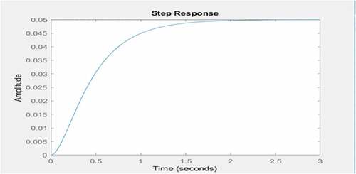
From Figure , the DC gain, which is the amplitude ratio of the steady-state response and the step input, is 0.05, which corresponds to a steady-state error of 0.95 for a rise time of 1 s and settling time of 1.5 s. This is a relatively large amplitude hence the need for adjustment using the PID control and the addition of transfer functions to reduce the rise time, steady time and eliminate steady-state error as shown in Figure .
Figure 5. Adjustment of the control of the rail car suspension system
From Figure , for the fully active system, the DC gain, which is the amplitude ratio of the steady-state response and the step, input increases to 0.25. This corresponds to a steady-state error of 0.75 for a rise time of 1 s, and settling time of 1.5 s. Comparing Figures and , it was observed that there was significant reduction in the value of the steady error while the rise and settling time remains the same.
Figure 6. Adjusted step response for the active system for 3 s (primary suspension system)
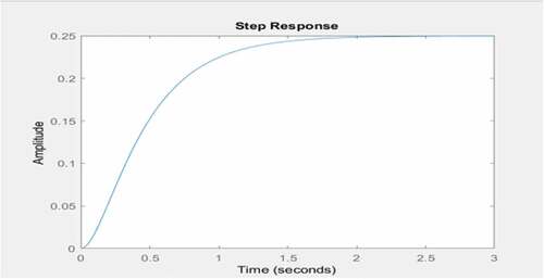
Figure shows the effect of rail disturbance on the performance of the rail car in relation to the front suspension system for the semiactive system. From the figure, the rail car moves uniformly until it encounters a disturbance at a time of 350 s, which offsets the balance for the next 50 s. The amplitude of the oscillation and overshoot was observed to increase as the time of oscillation increases and the system shows no damping compensation for the oscillations up to the period of 400 s and beyond. The amplitude of oscillation was found to be in the range of and
mm. High amplitude of oscillation with large overshoot and long settling time will eventually results in large deflections, unpleasant vibration and car body acceleration, bouncing, yawing, noise, discomfort for drivers and passengers and damage of some component parts of the rail car if not minimized.
Figure 7. Oscillation response of rail car to load disturbances (primary suspension system)
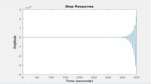
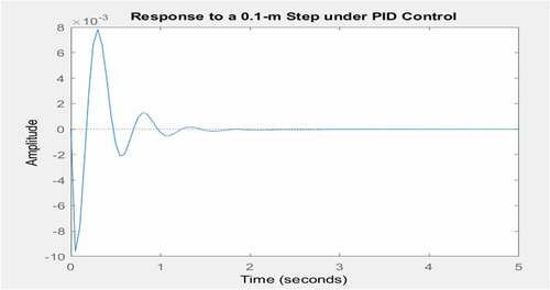
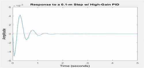
Figure shows the 0.1 m step under the PID control in order to minimize the high oscillating response, large overshoot and long settling time of the rail car system to disturbances. There was significant reduction in the amplitude from about to
mm with attendant reduction in the overshoot and settling time from over 400 to 2 s. The system shows large damping with short settling time. However, the percent overshoot can be further reduced by fine tuning the PID.
Figure 8. Response to a 0.1 m step under the PID control (primary suspension system)
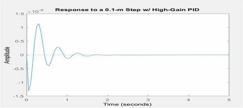
Upon fine tuning the PID control, the system response decreases further in terms of the amplitude of oscillation and overshoot (Figure ). This results in permissibly small deflections, absence of vibration, noise and car body acceleration with increased ride comfort.
Figure 9. Response to a 0.1 m step with high gain PID (primary suspension system)
The final oscillation step response of the front suspension system of the rail car to rail disturbances shown in Figure is mm with the PID control as opposed to initial value of
mm without control for the semiactive system, hence the PID has been above to effect a significant control of unpleasant vibrations as a result of rail disturbances which in turn improves the rail car stability and ride comfort.
The observed characteristic effect of the PID is presented in Table .
Table 3. Effects of controller parameters on closed-loop system
Figure shows the bode diagram for the actively control front suspension system comprising of the bandwidth, phase margin and frequency. The phase margin was found to be 42.2 at a frequency of 72.9 rad/s. The significance of this large phase margin is that the percent overshoot decreases with increase in the phase margin hence improving the rail car’s stability. Also higher close-loop bandwidth results in faster rise time. The rise time was found to be 0.05 s.
Figure 10. Bode diagram (primary suspension system)
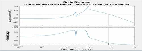
Figure shows the effect of rail disturbance on the performance of the rail car in relation to the rear suspension system for the semiactively controlled system. From the figure, the rail car encounters a disturbance, which offsets the balance from 0 s, and it took 45 s to settle and regain its stability. The amplitude of the oscillation and overshoot was observed to increase significantly at the beginning and decreases with time unlike the front suspension system. The amplitude of oscillation was found to be . This value is significantly large and will result in large deflections, vibration, noise and car body acceleration with decreased ride comfort if not controlled.
Figure 11. Oscillation response of rail car to rail disturbances (secondary suspension system)
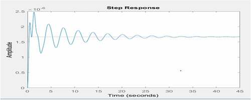
Figure shows the 0.1 m step under the PID control in order to minimize the high oscillating response, large overshoot and long settling time of the rear suspension system of rail car to disturbances. There was significant reduction in the amplitude overshoot by 60% from about to
mm and settling time from 40 to 2 s. The system also show high damping with short settling time. However, the percent overshoot can be further reduced for greater performance by fine-tuning the PID.
Figure 12. Response to a 0.1 m step under the PID control (secondary suspension system)
As shown in Figure , there was significant reduction in the amplitude and overshoot of the system by finetuning the PID controller via an iterative process of trial and error. The magnitude of the amplitude overshoot was further reduced to at a settling time of 2 mm, which is insignificant to cause vibration, noise and ride discomfort.
Figure 13. Final oscillation step response to rail disturbance (secondary suspension system)
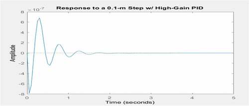
Figure shows the bode diagram for the actively controlled rear suspension system. The phase margin was found to be 40.4 at a frequency of 77.3 rad/s. The significance of this large phase margin is that the percent overshoot decreases with increase in the phase margin hence improving the system’s stability. Also higher close-loop bandwidth results in faster rise time. The rise time was found to be 0.025 s.
Figure 14. Bode diagram (secondary suspension system)
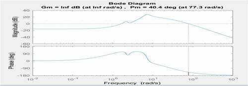
Figure shows the vertical acceleration of the rail car system for the semiactively controlled and actively controlled system. Vertical acceleration results when the rail car accelerates horizontally over a period and suddenly hits some rail irregularities causing the car to jump into the air and then drops back due to gravitational effect (bouncing). It causes ride discomfort if unchecked. The result in Figure indicated that the car moves vertically in both the positive and negative directions when it encountered rail irregularities or uneven rail profile with a maximum magnitude of about 0.32 m/s2 (in the positive direction) and −0.5 m/s2 (in the negative direction) and could not return to its initial position of rest after more than 2.5 s. The upward movement is significant which could cause accident or ride discomfort hence the introduction of active control system and the use of PID for fine tuning of process parameters checked the vertical acceleration with its value approximately zero. This will promote comfortable and safe ride.
Figure 15. Vertical acceleration for the controlled and uncontrolled systems
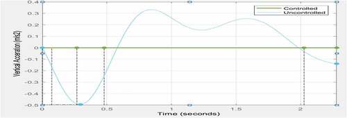
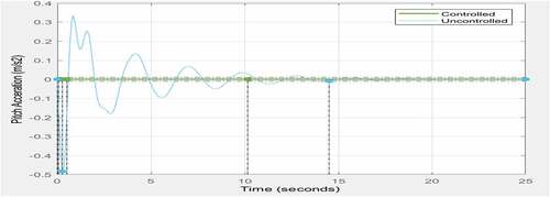
Figure shows the pitch acceleration which is the acceleration of a rail car about its lateral or Y axis for both the semiactive and fully active suspension systems. The result indicated that the car moves laterally in both the positive and negative directions when it encountered disturbances or uneven rail profile with a maximum magnitude of about 0.31 m/s2 (in the positive direction) and −0.5 m/s2 (in the negative direction) taking 14 s to return to its initial position. Upon the introduction of the active control system, the value of the pitch acceleration was reduced to approximately zero hence, the lateral movement becomes insignificant.
Figure 16. Pitch acceleration for the controlled and uncontrolled systems
From Figures and 1, the semiactive control system shows significant vertical and pitch acceleration as indicated by the blue color of its plot while the fully active suspension system shows negligible vertical and pitch acceleration with its value being zero as indicated by the green color of its plot. It is noteworthy to mention that normal acceleration of the rail car system is different from vertical acceleration (bouncing) and pitch acceleration. While the former tends to move the car linearly or horizontally, the latter displaces the car vertically or laterally resulting in vibrations or ride discomfort.
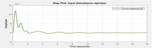
Figures and 1 show the rejection of disturbances from output sources by the system. The PID controller was further tuned to reject disturbances in the form of external (outside the system dynamics) and internal (as a result of variations that characterize the linear system dynamics). The active disturbance rejection uses the nonlinear steady-state error to check the total disturbances (sum of external and internal disturbances). With the feedback mechanism, the controller is able to use the system’s output to fine tune the input of the system such that the effect of various disturbances within and outside the system was minimized. As such, the total sinusoidal disturbances within the system could not create any significant ride discomfort. From Figures and 1, the downward slope of plot, which indicates the amplitude of oscillation with time for the external disturbances (above 1 m) and internal (10 m) was gradually reduced to zero after about 10 s using the disturbance rejection control. This indicates that the active control system was able to check unwanted vibrations and achieve good stability during the rail car operation.
Figure 17. Output disturbance rejection
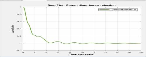
Figure 18. Input disturbance rejection
4. Conclusion
A rail car model with nine degrees of freedom with semiactive and fully active controls for optimum performance of the suspension systems was simulated with the use of MATLAB-Simulink. The PID controller was designed for the control of its active suspension system in order to minimize the effect of rail disturbances and improve the rail car stability. The amplitude of oscillations for both the primary and the secondary suspension systems reduces with the introduction of the PID and disturbance rejection controls. The actively controlled suspension systems show minimal vibrations resulting from disturbances compared to the semiactively suspension system whose vibrations was significant. In addition, the introduction of the PID control brought about significant reduction in the phase margin and bandwidth resulting in faster rise and settling time, elimination of steady-state error thereby increasing the stability and ride comfort of the rail car.
Table
Additional information
Funding
Notes on contributors
I. A. Daniyan
I. A. Daniyan is a Postdoctoral Research Fellow in the Department of Industrial Engineering, Tshwane University of Technology, Pretoria, South Africa. He played an active role toward the completion of this research.
K. Mpofu
K. Mpofu is the research leader of the De Department of Industrial Engineering, Tshwane University of Technology, Pretoria, South Africa. He contributed immensely toward the supervision of this research.
O. L. Daniyan
I. A. Daniyan is a Postdoctoral Research Fellow in the Department of Industrial Engineering, Tshwane University of Technology, Pretoria, South Africa. He played an active role toward the completion of this research.
O. L. Daniyan is a Chief Engineer and Head of Instrumentation Division, NASRDA Centre for Basic Space Science, Nsukka. He played a prominent role toward the completion of this research.
A. O. Adeodu
A. O. Adeodu is a Senior Lecturer in the Department of Mechanical and Mechatronics Engineering, Afe Babalola University Ado Ekiti, Nigeria. He played an active role toward the completion of this research.
Related Research Data
References
- Ahmed, M. I., Hazlina, M. Y., & Rashid, M. M. (2016). Modeling a small-scale test rig of quarter railway vehicle suspension system. International Journal of Robotics and Mechatronics, 2(4) 149–20.
- Al-Zughaibi, A., & Davies, H. (2015). Controller design for active suspension system of quarter car with unknown mass and time-delay. International Journal of Mechanical, Aerospace, Industrial, Mechatronic and Manufacturing Engineering, 9(8), 1484–1489.
- Arefsoliman, M. A. (2011) Adaptive LQR control strategy for active suspension system. SAE Technical Paper, 2011-01-0430.
- Bideleh, S. M. M., & Berbyuk, V. (2016). Global sensitivity analysis of bogie dynamics with respect to suspension components. Multibody System Dynamics, 37(2), 145–174. doi:10.1007/s11044-015-9497-0
- Colombo, E. F., Gialleonardo, E. D., Facchinetti, A., & Bruni, S. (2014). Active car body roll control in railway vehicles using hydraulic actuation. Control Engineering Practice, 31, 24–34. doi:10.1016/j.conengprac.2014.05.010
- Eriş, O., Ergenç, A. F., & Kurtulan, S. (2014). Use of non-identical multiple delayed resonators in active suspension systems of railway vehicles. International Conference on Control System, Computing and Learning. Penang, Malaysia, November 28–30.
- Fazio, A. E., & Hickey, T. R. (2003). Designing new light rail: Taking engineering beyond vanilla circular E-CO58. 9th National Light Rail Transit Conference, Transportation Research Board. pp. 1–5.
- Gohrle, C., Schindler, A., Wagner, A., & Sawodny, O. (2014). Design and vehicle implementation of preview active suspension controllers. IEEE Transactions on Control Systems Technology, 22(3), 1135–1142. doi:10.1109/TCST.2013.2272342
- Gowda, D. V., & Sadashiva, C. (2014). Comparative analysis of passive and semi-active suspension system for quarter car model using PID controller,” International Conf. on Recent Trends in Signal Processing, Image Processing and VLSI (ICrtSIV), Bangalore, India, 2014. pp. 1–6.
- Ha, S. H., Choi, S. B., & Lee, K. S. (2012). Ride quality evaluation of railway vehicle suspension system featured by magnetorheological fluid damper. Advanced Science Letters, 12, 209–213. doi:10.1166/asl.2012.2740
- Hasbullah, F., & Faris, W. F. (2017). Simulation of disturbance rejection control of half-car active suspension system using active disturbance rejection control with decoupling transformation. IOP Conf. Series. Journal of Physics: Conference Series, 949(2017), 012025. doi:10.1088/17426596/949/1/012025
- Hasbullah, F., Faris, W. F., Darsivan, F. J., & Abdelrahman, M. (2015). Ride comfort performance of a vehicle using active suspension system with active disturbance rejection control,”. International Journal of Vehicle Noise Vibration, 11(1), 78–101. doi:10.1504/IJVNV.2015.067995
- Herbst, G. (2013). A simulative study on active disturbance rejection control (ADRC) as a control tool for practitioners. Electronics, 2(3), 246–279. doi:10.3390/electronics2030246
- Jiang, Z., & R E, C. (2012). A fully dynamic magnetorheological fluid damper model. Smart Materials and Structures, 21, 65002. doi:10.1088/0964-1726/21/6/065002
- Jin, X.-S., Xiao, X.-B., Ling, L., Zhou, L., & Xiong, J.-Y. (2013). Study on safety boundary for high-speed trains running in severe environments. International Journal of Rail Transportation, 1(1–2), 87–108. doi:10.1080/23248378.2013.790138
- Kim, H. C., Choi, S. B., & Lee, G. S. (2013) Performance analysis of a semi-active railway vehicle suspension featuring MR dampers. In: Proceedings of the 3rd International Conference on Mechanical, Production and Automobile Engineering, Bali, Indonesia, 4–5 January 2013. Singapore: Planetary Scientific Research Centre.
- Kim, H. C., Choi, S. B., & Lee, G. S. (2014) Performance analysis of a semi-active railway vehicle suspension featuring MR dampers. In: SPIE smart structures and materials + non-destructive evaluation and health monitoring, San Diego, CA, 9 March 2014, pp.905711. Bellingham, WA: International Society for Optics and Photonics (SPIE).
- Kumar, P. S., Sivakumar, K., Kanagarajan, R., & Kuberan, S. (2018). 2799 Adaptive neuro fuzzy inference system control of active suspension system with actuator dynamics. Journal of Vibroengineering, 20(1), 541–549. doi:10.21595/jve.2017.18379
- Li, H., Liu, H., Gao, H., & Shi, P. (2012). Reliable fuzzy control for active suspension systems with actuator delay and fault. IEEE Transactions on Fuzzy Systems, 20(2), 342–357. doi:10.1109/TFUZZ.2011.2174244
- Ling, L., Xiao, X.-B., Xiong, J.-Y., Zhou, L., Wen, Z.-F., & Jin, X.-S. (2014). A three-dimensional model for coupling dynamics analysis of high speed train-track system. Journal of Zhejiang University-science A (Applied Physics & Engineering), 15(2), 964-983.
- Matamoros-Sanchez, A. Z., & Goodall, R. M. (2015). Novel mechatronic solutions incorporating inerters for railway vehicle vertical secondary suspensions. Vehicle System Dynamics, 53(2), 13–136.
- Minakaldas, M. S., & Arefsoliman, M. A. (2014) Influence of active suspension preview control on vehicle ride and braking performance. SAE Technical Paper, 2014-01-0862.
- Nakajima, T., Shimokawa, Y., Mizuno, M., & Sugiyama, H. (2014). Air suspension system model coupled with leveling and differential pressure valves for railroad vehicle dynamics simulation. Journal of Computational and Nonlinear Dynamics, 9, 1–9. doi:10.1115/1.4026275
- Nguyen, S. D., & Choi, S. B. (2012). A new neuro-fuzzy training algorithm for identifying dynamic characteristics of smart dampers. Smart Materials and Structures, 21, 1–14. doi:10.1088/0964-1726/21/8/085021
- Nguyen, S. D., & Choi, S. B. (2013). A novel minimum–Maximum data-clustering algorithm for vibration control of a semi-active vehicle suspension system. IMechE Part D. Journal of Automobile Engineering, 227(9), 1242–1254. doi:10.1177/0954407013492926
- Nguyen, S. D., & Nguyen, Q. H. (2017). Design of active suspension controller for train cars based on sliding mode control, uncertainty observer and neuro-fuzzy system. Journal of Vibration and Control, 23(8), 1334–1353. doi:10.1177/1077546315592767
- Nguyen, S. D., Nguyen, Q. H., & Choi, S. B. (2014). Hybrid clustering based fuzzy structure for vibration control – Part 1: Anovel algorithm for building neuro-fuzzy system. Mechanical Systems and Signal Processing, 50-51, 510–525. doi:10.1016/j.ymssp.2014.04.021
- Oh, J.-S., Shin, Y.-J., Koo, H.-W., Kim, H.-C., Park, J., & Choi, S.-B. (2016). Vibration control of a semi-active railway vehicle suspension with magneto-rheological dampers. Advances in Mechanical Engineering, 8(4), 1–13. doi:10.1177/1687814016643638
- Podwórna, M. (2015). Modelling of random vertical irregularities of railway tracks. International Journal of Applied Mechanical Engineering, 20, 647. doi:10.1515/ijame-2015-0043
- Shao-Juan, L., Zhong-Hua, H., & Yi-Zhang, C. (2014). Automobile active suspension system with fuzzy control. Journal of Central South University of Technology, 11(2), 206–209.
- Sharma, R. C., & Sharma, S. K. (2018). Sensitivity analysis of three-wheel vehicle’s suspension parameters influencing ride behaviour. Noise & Vibration Worldwide, 49(7–8), 272–280. doi:10.1177/0957456518796846
- Sharma, S. K., & Kumar, A. (2014). A comparative study of Indian and worldwide railways. International Journal of Mechanical Engineering and Robotics Research, 1(1), 114–120.
- Sharma, S. K., & Kumar, A. (2016). Dynamics analysis of wheel rail contact using FEA. Procedia Engineering, 144, 1119–1128. doi:10.1016/j.proeng.2016.05.076
- Sharma, S. K., & Kumar, A. (2017). Ride performance of a high-speed rail vehicle using controlled semi active suspension system. Smart Materials and Structures, 26(1–19), 055026. doi:10.1088/1361-665X/aa68f7
- Sharma, S. K., & Kumar, A. (2018). Disturbance rejection and force-tracking controller of nonlinear lateral vibrations in passenger rail vehicle using magnetorheological fluid damper. Journal of Intelligent Material Systems and Structures, 29(2), 279–297. doi:10.1177/1045389X17721051
- Shin, D., Lee, G., Yi, K., & Noh, K. (2015). Motorized vehicle active suspension damper control with dynamic friction and actuator delay compensation for a better ride quality. Proceedings of the Institution of Mechanical Engineers, Part D: Journal of Automobile Engineering, 1–16. doi:10.1177/0954407015598670
- Shin, Y.-J., You, W.-H., Hur, H.-M., & Park, J.-H. (2014). H ∞ control of railway vehicle suspension with MR damper using scaled roller rig. Smart Materials and Structures, 23, 95023. doi:10.1088/0964-1726/23/9/095023
- Suarez, B., Felez, J., Maroto, J., & Rodriguez, P. (2013). Sensitivity analysis to assess the influence of the inertial properties of railway vehicle bodies on the vehicle’s dynamic behaviour. Vehicle System Dynamics, 51(2), 251–279. doi:10.1080/00423114.2012.725851
- Sun, S., Deng, H., Li, W., Du, H., Ni, Y. Q., Zhang, J., & Yang, J. (2013). Improving the critical speeds of high-speed trains using magnetorheological technology. Smart Materials and Structures, 22. doi:10.1088/0964-1726/22/11/115012
- Sun, Y., Gong, D., & Zhou, J. (2016). Study on vibration reduction design of suspended equipment of high speed railway vehicles. Journal of Physics: Conference Series, 744:12212.
- Ulum, Z., Affaf, M., Salmah, & Suparwanto, A. (2017) Active suspension systems design of a light rail vehicle using MPC with preview information disturbance”. 5th International Conference on Instrumentation, Control, and Automation (ICA) Yogyakarta, Indonesia, August 9-11, 2017. pp. 18–23.
- Wang, G., Chen, C., & Yu, S. (2017). Robust non-fragile finite-frequency static output-feedback control for active suspension systems. Mechanical Systems and Signal Processing, 91, 41–56. doi:10.1016/j.ymssp.2016.12.039
- Yamamoto, A., Sugai, H., Kanda, R., & Buma, S. (2014) “Preview ride comfort control for electric active suspension (eActive3)” SAE Technical Paper, 2014-01-0057.
- Yao, J. L., & Shi, W. K. (2013). Development of a sliding mode controller for semi-active vehicle suspensions. Journal of Vibration and Control, 19, 1152–1160. doi:10.1177/1077546312441045
- Zhang, B. L., Han, Q. L., Zhang, X. M., & Yu, X. (2013). Sliding mode control with mixed current and delayed states for offshore steel jacket platforms. IEEE Transactions on Control Systems Technology, 22, 1769–1783. doi:10.1109/TCST.2013.2293401
- Zhu, S., Du, H., Zhang, N., & Wang, L. (2014). Development of a new model for roll-plane active hydraulically interconnected suspension. SAE International Journal of Passenger Cars – Mechanical Systems, 7(2), 447–457. doi:10.4271/2014-01-0053
- Zolotas, A. G., & Goodall, R. M. (2007). Modelling and con-trol of railway vehicle suspensions. In M. C. Turner & D. G. Bates (Eds.), Lecture notes in control and information sciences, mathematical methods for robust and nonlinear control (pp. 373–412). New York: Springer.
- Zong, L. H., Gong, X. L., Xuan, S. H., & Guo, C. Y. (2013). Semi-active H∞ control of high-speed railway vehicle suspension with magnetorheological dampers. Vehicle System Dynamics, 51(5), 600–626. doi:10.1080/00423114.2012.758858