
 ?Mathematical formulae have been encoded as MathML and are displayed in this HTML version using MathJax in order to improve their display. Uncheck the box to turn MathJax off. This feature requires Javascript. Click on a formula to zoom.
Abstract
In this research, we generalize a family of electronic parametric oscillators in the fractional domain by using a state of the art circuit element namely fractional memristor. Such family of parametric oscillators is the memristor based Wien family which is an extension of the normal Wien family. Noted that such normal Wien family is one family of the simplest second-order nonparametric oscillators. We derive the equations of the range of oscillating frequency, sustained oscillating frequency, sustained oscillating condition and the output voltage by using our mathematical model of the fractional memristor as the basis. With the obtained results and numerical simulations, the effects of the fractional memristor to the generalized parametric oscillators have been studied where the validation has been performed based on the SPICE HP memristor model. We have found that those oscillators with the fractional memristor of order greater than unity are more preferable.
PUBLIC INTEREST STATEMENT
The electronic oscillators have been found to be the famous signal generators. Among various oscillators, the Wien oscillator is one of the simplest electronic oscillators. By replacing one of its resistor with the memristor, the oscillator become a parametric one thus it has unique properties which are different from those of the normal oscillator, for example, time-dependent pole locations, oscillating frequency, etc.
On the other hand, a state of the art electronic device namely fractional memristor have been developed. Compared to this recently developed device, the conventional memristor is merely its special case. Motivated by such far more generality of the fractional memristor and the interesting properties of parametric Wien oscillator, we generalize the entire family of this oscillator by applying such newly developed device.
1. Introduction
Mathematically, the oscillation refers to the continuous recurrence of periodic waveform. The oscillation is parametric if the oscillatory system under consideration is time varying. Many examples of parametric oscillation have been previously presented by Komine et al. (Komine, Galliou, & Makarov, Citation2003). In electronic engineering, those circuits which generate oscillatory outputs called oscillators have been found to be the famous signal generators. Among various oscillators, Wien oscillator has been found to be one of the simplest second-order oscillators. Such Wien oscillator has four basic structures, which constitute the Wien family. By replacing one of the resistor in the Wien oscillator by the memristor, the memristor-based Wien oscillator can be obtained (Talukdar, Radwan, & Salama, Citation2011). This memristor-based oscillator has been found to be an electronic parametric oscillatory system because the coefficients of its state space representation are time dependent thus it is a linear time varying system. Moreover, it has been shown that this parametric oscillator has unique properties, which are different from those of a nonparametric Wien oscillator, for example, time-dependent pole locations, oscillating frequency, etc. (Talukdar et al., Citation2011).
The memristor, which is the key element of this oscillator, is the fourth electrical circuit element that has been theoretically found by Chua since 1971 (Chua, Citation1971). Since the memristor is simply the resistor with memory, it can be thought of as a generalization of resistor. Therefore the memristor-based Wien oscillator has been found to be a generalization of the normal Wien oscillator. For decades after Chua proposed his original work, the memristor has been practically realized by a research group in Hewlett Packard (HP) labs in 2008 (Strukov, Snider, Stewart, & Williams, Citation2008). Apart from the aforesaid parametric oscillator, the memristor has also been applied in various applications, for example, DRAM, signal processing, neural networks, programmable logic, cross bar switch, passive switch, control systems etc. (Pershin & Di Ventra, Citation2010), (Mouttet, Citation2007), (Jeong, Lee, Choi, & Kim, Citation2009).
Recently, a state of the art electrical circuit element namely fractional memristor have been existed. This circuit element can be obtained from a further generalization of the memristor in the fractional domain by using the concept of fractional calculus, which have been adopted in various disciplines, for example, biomedical engineering (Jesus, Machado & Cunha, Citation2008), (Tang et al., Citation2009), control system (Charef, Citation2006), (Vinagre & Feliu, Citation2007), (Matušů, Citation2011) and electronic engineering (Dorčák, Terpák, Petráš, & Dorčáková, Citation2007), (Krishna, Reddy, & Santa Kumari, Citation2008), (Radwan & Elwakil, Citation2012). It can be seen that the memristor is merely a special case of the fractional memristor as it is simply the fractional memristor of first order. Motivated by the far more generality of the fractional memristor and the interesting properties of memristor based Wien oscillators, we generalize this family of parametric oscillators in the fractional domain by applying the fractional memristor. We firstly derive the mathematical model of the fractional memristor for being the basis of our work. Later, we derive the equations of the range of oscillating frequency, sustained oscillating frequency and sustained oscillating condition, which are the important features of the parametric Wien family. We also solve the state space equations of these fractional memristor-based parametric oscillators for determining the output voltage. By using these results and numerical simulations with MATHEMATICA, the effects of the order of fractional memristor to the aforesaid important features and the output voltage have been studied. We also compare our simulation results to those obtained by using the circuit simulations with SPICE model of HP memristor proposed by Biolek et al. (Biolek, Biolek & Biolkova, Citation2009a, August), (Biolek, Biolek & Biolkova, Citation2009b), (Biolek, Biolek, Biolkova, & Kolka, Citation2014). As a result, the strong agreements can be observed. Moreover, we have found that the generalized parametric oscillators with the fractional memristor of order greater than unity are more preferable.
In the following section, some background theory on the memristor and Wien family of oscillators will be briefly given. The mathematical modelling of fractional memristor will be shown in section 3 followed by the derivation of the aforesaid equations in section 4. In section 5, the effects of the order of fractional memristor to the aforementioned important features and output voltage will be studied where some analytical discussions and discussions on other interesting issue will be given in section 6. Finally, the conclusion will be drawn in section 7.
Figure 2. Type B Wien oscillator
Figure 3. Type C Wien oscillator
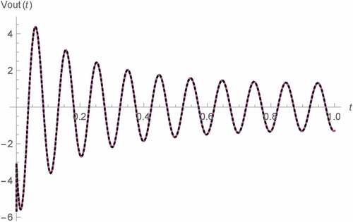
Figure 6. Vout(t) v.s. t for 0 s < t < 1 s of Type B Wien oscillator: fractional memristor with a = 0.75 (blue), fractional memristor with a = 1 (green), fractional memristor with a = 1.25 (red) and SPICE HP memristor model (dots)
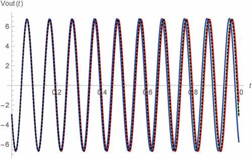
Figure 13. Vout(t) v.s. M(t) of Type A Wien oscillator: fractional memristor with a = 1 (green) and SPICE HP memristor model (dots)
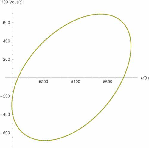
Figure 15. Vout(t) v.s. M(t) of Type B Wien oscillator: fractional memristor with a = 0.75
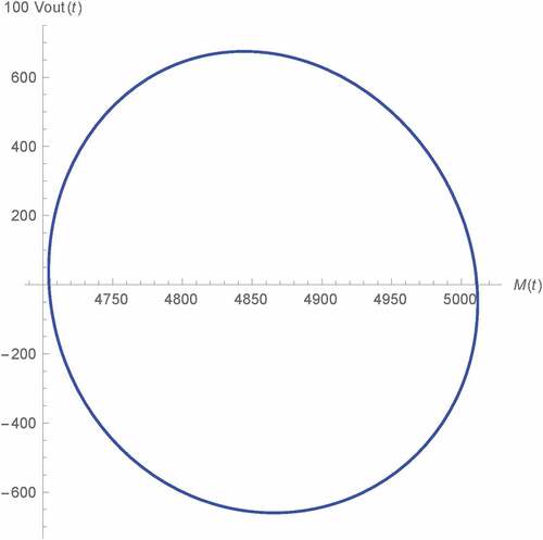
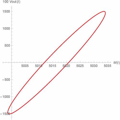
Figure 16. Vout(t) v.s. M(t) of Type B Wien oscillator: fractional memristor with a = 1 (green) and SPICE HP memristor model (dots)
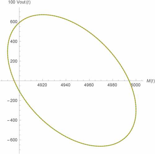
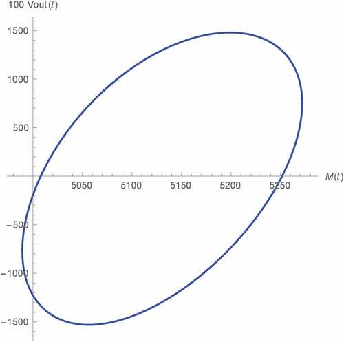
Figure 17. Vout(t) v.s. M(t) of Type B Wien oscillator: fractional memristor with a = 1.25
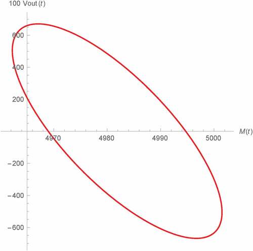
Figure 19. Vout(t) v.s. M(t) of Types C and D Wien oscillator: fractional memristor with a = 1 (green) and HP memristor (black dots)
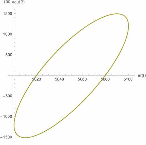
Figure 22. Vout(t) v.s. t of Type A Wien oscillator (ß = 1 and γ = 0.95): fractional memristor with a = 1.25 (line), order 1.25 SPICE HP memristor model (dots)
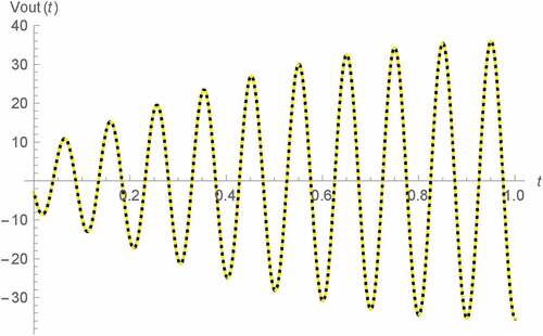
Figure 23. Vout(t) v.s. t of Type A Wien oscillator (ß = 0.95 and γ = 0.95): fractional memristor with a = 1.25 (line), order 1.25 SPICE HP memristor model (dots)
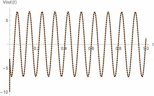
Figure 24. Vout(t) v.s. t of Type A Wien oscillator (nonlinear dopant drift model, ß = 0.95 and γ = 0.95): fractional memristor with a = 1.25 (line), order 1.25 SPICE HP memristor model (dots)
2. Background theory
2.1. Memristor
Memristor is a nonlinear electrical circuit element. This circuit element relates the instantaneous flux (ϕ(t)) and charge (q(t)) through the following relationship
where M(t) denotes the memristance which is time variant.
According to (Strukov et al., Citation2008), M(t) of the HP memristor can be given in terms of the minimum and maximum values of M(t) denoted by Mon and Moff and the state variable (x(t)) as
where x(t) which is dimensionless, can be given in term of the memristor’s current (i(t)) by
Noted that k = μMon/D2 where μ and D respectively stand for the ion mobility and semiconductor film of thickness. Therefore the dimension of k is (A∙s)−1. Moreover, stands for the window function, which has been used for modelling the boundary effect of the device, that is, 0 ≤ x(t) ≤ 1 thus Mon ≤ M(t) ≤ Moff.
2.2. Wien family of oscillators
Wien family of oscillators or Wien family in short are a family of the simplest second-order oscillators. There are four members in this family where each of them has a unique circuital structure. So, they are referred to as the Wien oscillator of type A, B, C and D which can be respectively depicted in Figures –.
Figure 1. Type A Wien oscillator
Figure 4. Type D Wien oscillator
Despite their different structures, the oscillating condition and frequency of oscillation (fosc) of these members of Wien family can be commonly given by (4) and (5) respectively where C = C1 = C2. Such condition and fosc are time independent as R1, R2, C1 and C2 do.
For the memristor based Wien family, R1 has been replaced by a memristor (Talukdar et al., Citation2011). Therefore, the oscillating condition and fosc become
As a result, both oscillating condition and fosc are now time variant thus the parametric oscillation can be achieved by the usage of memristor.
3. The mathematical model of fractional memristor
By generalizing the memristor in the fractional domain, the fractional memristor can be obtained. Such generalization can be performed by applying the fractional calculus concept to the memristor’s state equation. According to the previous fractional memristor modelling attempts (Fouda & Radwan, Citation2013), (Fouda & Radwan, Citation2015), such fractional domain state equation can be given by
where α stands for the order of the fractional derivative which is not strictly integer but arbitrary real value.
However, as x(t) is dimensionless, the dimension of the LHS of this previous generalized is given by sec−α where that of the RHS is sec−1, which means that a dimensional inconsistency has been existed. Moreover, the boundary effect has also been ignored as f(x(t)) has been excluded. Therefore, the fractional time component, σ which has the dimension of s (Gómez-Aguilar, Rosales-García, Bernal-Alvarado, Córdova-Fraga, & Guzmán-Cabrera, Citation2012), (Podlubny, Citation2002), (Banchuin, Citation2017), must be introduced and (3) must be used as the basis for handling these issues. As a result, the following fractional domain state equation which has been adopted in this study, can be obtained
Similarly to that of the RHS, the dimension of the LHS of (7) is sec−1 thus the dimensional inconsistency issue has been resolved. Moreover, the boundary effect has been now taken into account by the inclusion of . Noted also that (9) can be reduced to (3) when α = 1 despite the presence of σ as σα −1 become 1 with such value of α.
Since the linear dopant drift has been assumed by Talukdar et al. according to their adopted mathematical model of the basis memristor (Radwan, Zidan & Salama, Citation2010b), (Radwan, Zidan & Salama, Citation2010a, August), we use the following in our work for ceteris paribus.
As a result, we have
By using the Riemann-Liouville fractional order integral (Sabatier, Agrawal, & Machado, Citation2007), x(t) can be found as
where x(0) denotes the initial value of x(t) and Г() stands for the Gamma function (Beyer, Citation2018), Moreover, we define K = kσ1-α for simplicity thus the dimensions of K is A−1s−α.
Since it can be seen from (2) that
where Md = Moff-Mon, the initial memristance value i.e. M(0), can be immediately defined as
Therefore M(t) of the fractional memristor can be obtained by using (2), (10) and (12) as
Since the dimension of i(t) is A, that of is Ω. Therefore, the dimension of M(t) is remained Ω similarly to those of the traditional resistance and memristance of the conventional memristor.
By using (15), M(t) of the fractional memristor due to any exciting signal can be determined. If we assume that such signal is a sinusoidal one with Im, f and θ as its arbitrary peak value, frequency and phase angle, M(t) can be obtained by applying the approximation of the fractional order integration of sinusoidal function (Kilbas, Srivastava, & Trujillo, Citation2006) as follows
4. The fractional memristor based Wien family
This generalized parametric Wien family can be obtained by using the fractional memristor for R1 in the Wien oscillator of all types. As a result, the state space representations of all members of the family can be commonly given by
where . Noted also that VC1(t) and VC2(t) denote the voltage dropped across C1 and C2 and
where M(t) is given by (16) as the fractional memristor is applied by the sinusoidal signal because the Wien oscillator is a sinusoidal oscillator.
Since M(t) is in terms of trigonometric function, it exhibits an oscillatory behavior and so does fosc as fosc is depended on M(t). Similarly to its conventional memristor based prototype, fosc of the fractional memristor based Wien family is also related to M(t) by (7) thus it is inversely proportional to M(t). As a result, fosc reaches its maximum when M(t) reaches its minimum and vice versa. By using (7) with M(t) as given by (16), it has been found that such maximum and minimum value of fosc, that is, fmax and fmin, can be respectively determined by solving (17) and (18) which are applicable if and only if Im > 0.
For Im < 0 on the other hand, (19) and (20) must be applied instead.
Before we proceed further, it should be mentioned here that (17)–(20) and the ongoing ones have been derived by assuming that has been satisfied in order to ensure the proper operations of the oscillators as previously did by Talukdar et al. At this point, it can be stated that the range of fosc (Δfosc) can be simply obtained in terms of fmax and fmin as follows
Similarly to its conventional memristor-based progenitor, the fractional memristor-based Wien family finally reach the sustained oscillation state despite the fluctuation in fosc. At such state, fosc become constant at its average value (favr) where we have found that
Moreover, the following condition must be satisfied for ensuring the occurrence of sustained oscillation.
In order to determine the output voltage (Vout(t)), (17) must be firstly solved. The solution of (17) can be found as
where
Noted also that I is a 2 dimensional identity matrix.
Despite the similar VC1(t) and VC2(t) as the state space representations of all members of the family can be commonly given by (17), each member of the fractional memristor-based Wien family employs different Vout(t) due to its unique circuit topology. For type A and type B fractional memristor-based Wien oscillator, Vout(t) can be given by either (26) or (27) where that of type C and type D can be given by either (28) or (29).
5. The fractional domain behavioral analysis
In order to do so, the effects of α which is the fractional domain parameter, to favr, sustained oscillating condition, Δfosc and Vout(t) which are the key features of this parametric Wien family, must be analyzed by using those equations derived in the previous section and numerical simulations. Noted also that all members of the family have been studied and the analytical discussion on the obtained results have also been made as will be seen in the subsequent section. This is unlike the previous analysis attempt which only type A oscillator has been analyzed where merely some features has been considered and θ = 0 rad has been assumed even in the mathematical formulations for simplicity (Banchuin, Citation2018). Throughout this work, we have assumed that C1 = C2 = C = 3.2 μF and R2 = 5 kΩ for all members of the family (Talukdar et al., Citation2011). However, we use R4 = 10 kΩ unlike Talukdar et al. We have also assumed that D = 10 nm, σ = 1 s, Moff = 16 kΩ, Mon = 100 Ω and μ = 10−14 m2(s∙V)−1. For analyzing the effects of α, we let it take three possible values, that is, 0.75 which is lower than 1, 1 which makes the fractional memristor be equivalent to an conventional one and 1.25 which is greater than 1. As results, favr, R3/R4 for ensuring sustained oscillation and Δfosc have been tabulated against α and M(0) for all types of fractional memristor-based Wien oscillator as shown in Tables –.
Table 1. FAVR (HZ) of fractional memristor-based Type A Wien oscillator
Table 2. FAVR (HZ) of fractional memristor-based Type B Wien oscillator
Table 3. FAVR (HZ) of fractional memristor-based Types C and D Wien oscillator
Table 4. R3/R4 of fractional memristor-based Type A Wien oscillator
Table 5. R3/R4 of fractional memristor-based Type B Wien oscillator
Table 6. R3/R4 of fractional memristor-based Types C and D Wien oscillator
Table 7. ΔFOSC (HZ) of fractional memristor-based Type A Wien oscillator
Table 8. ΔFOSC (HZ) of fractional memristor-based Type B Wien oscillator
Table 9. ΔFOSC (HZ) of fractional memristor-based Types C and D Wien oscillator
Apart from being inversely proportional to M(0) similarly to that of the memristor-based Wien family, favr is directly proportional to α for the fractional memristor based oscillators of type A, C and D as can be seen from Table and . On the other hand, it can be seen from Table that the opposite relationship can be observed from type B circuit. From Table and , it can be observed that R3/R4 for sustained oscillation guaranteed is directly proportional to M(0) but inversely proportional to α for the oscillators of type A, C and D. On the other hand, such R3/R4 become directly proportional to α for type B which yields lower values of R3/R4 than those of the other types when α ≤ 1 as can be seen from Table . Therefore, type B oscillator requires smaller R3 than those of the others for similarly obtaining sustained oscillation. It can also be seen that the effects of α to favr and R3/R4 for ensuring sustained oscillation are small due to their insignificant dependencies of both quantities on α. This is not surprising because we have found in this scenario that
Therefore, both favr and R3/R4 are largely depended on M(0), which is independent of α, as can be seen from (20) and (21).
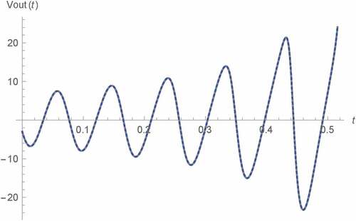
However, we have found that α significantly affects Δfosc as Tables – shows that Δfosc is inversely proportional to α at significant degree beside being inversely proportional to M(0). Therefore, we promote the usage of fractional memristor with α > 1 for increasing the chance of obtaining sustained oscillation according to its lowest Δfosc. These tables also show that fractional memristor-based oscillator of type A employs minimum Δfosc thus it has been found to be more preferable than the others due to its best chance of obtaining the sustained oscillation. Moreover, we simulate Vout(t) for various α’s as depicted in Figures – where we assume that M(0) = 5 kΩ. In Figures –, 0 s < t < 1 s which refers to the early state of Vout(t) have been assumed. On the other hand, 99 s < t < 100 s which refers to the asymptotic state, have been assumed for the rests.
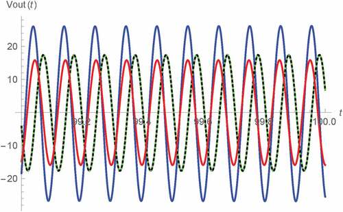
Figure 9. Vout(t) v.s. t for 99 s < t < 100 s of Type B Wien oscillator: fractional memristor with a = 0.75 (blue), fractional memristor with a = 1 (green), fractional memristor with a = 1.25 (red) and SPICE HP memristor model (dots)
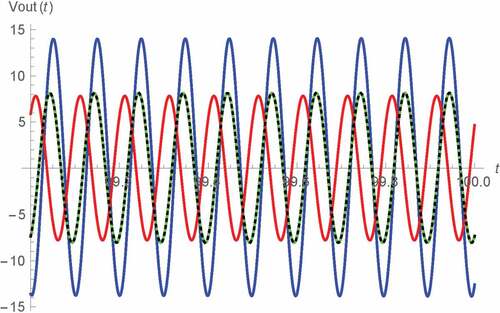
Figure 5. Vout(t) v.s. t for 0 s < t < 1 s of Type A Wien oscillator: fractional memristor with a = 0.75 (blue), fractional memristor with a = 1 (green), fractional memristor with a = 1.25 (red) and SPICE HP memristor model (dots)
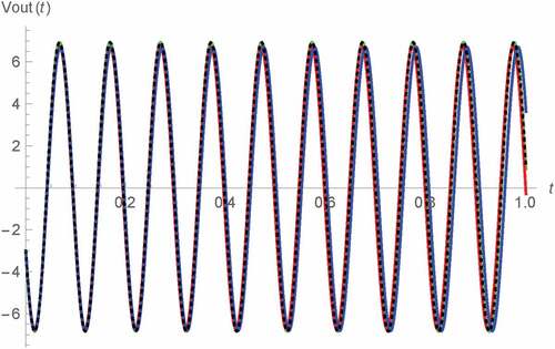
Figure 7. Vout(t) v.s. t for 0 s < t < 1 s of Types C and D Wien oscillators: fractional memristor with a = 0.75 (blue), fractional memristor with a = 1 (green), fractional memristor with a = 1.25 (red) and SPICE HP memristor model (dots)
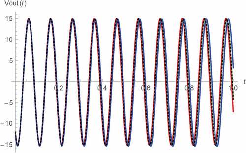
For the validation of our results, the comparison of our results with α = 1 to their corresponding SPICE HP memristor model-based benchmarks have been made as also shown in the figures. The schematic diagram of SPICE HP memristor model can be shown as depicted in Figure (Biolek, Biolek & Biolkova, Citation2009b), (Biolek et al., Citation2014), (Kozma, Pino, & Pazienza, Citation2012) where TE and BE represent the top and bottom electrodes of the memristor (Kozma et al., Citation2012), i(t) denotes the current flowing through the memristor and x(t), which is physically the normalized width of the doped layer is now emulated in term of the voltage dropped across the parallel combination of conventional capacitor and resistor thus x(0) can be emulated as the capacitor’s initial voltage. Those results with α = 1 have been chosen as the fractional memristor with such order is equivalent to the conventional one. Moreover, the circuit simulation by using the SPICE HP memristor model has been found to be convenient and also more preferable than using other HP memristor emulator circuits, for example, those proposed by Kim et al. (Kim, Sah, Yang, Cho, & Chua, Citation2012), Yang et al. (Yang, Cho, Sah, Kim, & Jung, Citation2012), Sah et al. (Sah, Yang, Kim, & Chua, Citation2012), Olumodeji (Olumodeji & Gottardi, Citation2017), etc. This is because the HP memristor which has been adopted in this work as our basis of the fractional memristor, is a specifically fabricated electronic device at nanometer level that employs a unique characteristic namely the boundary effect which makes the memristance be fixed either at on-state value or off-state value when become saturated (Anusudha & Prabaharan, Citation2018). This effect has been taken into account by the SPICE HP memristor model despite being ignored by those other HP memristor emulator circuits. Therefore, the SPICE HP memristor model has been found to be one of the best so far HP memristor emulator for computer simulation to the knowledge of the author. From Figures –, the strong agreements between our results and the SPICE HP memristor model-based counterparts which verify the validity of our results, can be observed. Noted also that our asymptotic Vout(t) of type A oscillator depicted in Figure bears a strong resemblance to the previous result (Banchuin, Citation2018) as we let θ = 0 rad for our numerical simulation and different outcomes can be expected if we assume nonzero θ.
Figure 11. The schematic of SPICE HP memristor model
By comparing Figures – to Figures –, we have found that the magnitude of Vout(t) become significantly greater at asymptotic state which sustained oscillation has occurred, and the increasing in such magnitude is inversely proportional to α. This promotes the usage of the fractional memristor with α > 1 for enhancing the constancy in magnitude of the oscillator’s output. It can also be observed that the magnitudes of Vout(t) of the oscillators of type C and D are significantly larger than to those of the others. This is because R3 > M(t) for all t according to the assumed parameters stated above. Therefore the magnitudes of Vout(t) of type C and D which are directly proportional to R3 as can be seen from (29), are significantly larger than to those of types A and B, which in turn are proportional to M(t) as shown by (27). Before proceed further, it should be mentioned here that there exist phase differences between Vout(t)’s for different α’s at the asymptotic state. These phase differences have been caused by the accumulation of the differences in fosc of Vout(t)’s for different α’s occurred during the early state as the phase angle is mathematically the integration of frequency. Such differences in fosc occurred because the sustained oscillation is not yet achieved during the early state thus fosc is still fluctuated. Since α significantly affects Δfosc, it affects the fluctuation of fosc therefore different α’s causes different fluctuations and the differences in fosc thus the phase differences have been yielded.
Figure 8. Vout(t) v.s. t for 99 s < t < 100 s of Type A Wien oscillator: fractional memristor with a = 0.75 (blue), fractional memristor with a = 1 (green), fractional memristor with a = 1.25 (red) and SPICE HP memristor model (dots)
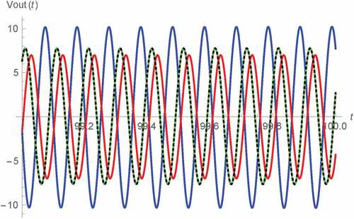
Figure 10. Vout(t) v.s. t for 99 s < t < 100 s of Types C and D Wien oscillators: fractional memristor with a = 0.75 (blue), fractional memristor with a = 1 (green), fractional memristor with a = 1.25 (red) and SPICE HP memristor model (dots)
Now, we simulate Vout(t) at asymptotic state against M(t) for various α’s as depicted in Figures –, where M(0) = 5 kΩ has also been assumed and the vertical axes have been multiplied by 100 for visibility. Again, the comparison of those results with α = 1 to their corresponding SPICE HP memristor model-based benchmarks have also been made where strong agreements which validate our results, can also be observed. Noted also that the simulation results of type A oscillator depicted in Figures – are very similar to the previous results (Banchuin, Citation2018) as we let θ = 0 rad. From these lissajous curves, we have found that Vout(t) is of the same frequency as M(t). Such frequency is given by favr as the sustained oscillation has been already achieved. It has also been found that the phase difference between Vout(t) and M(t) which is less than π/2 rad, is inversely proportional to α for the type A, C and D oscillators. For type B oscillator on the other hand, we have found that such phase difference which lies between π/2 rad to π rad, is directly proportional to α. It can also be seen that the memory effects and the linearity in the relationship between M(t) and Vout(t) are inversely and directly proportional to α respectively where the oscillators of type A and B have been found to be more linear than the rests assuming the same α. Therefore, we promote the usage of either type A or type B oscillator and the fractional memristor with α > 1 in those applications which linearity issues are crucial.
Figure 12. Vout(t) v.s. M(t) of Type A Wien oscillator: fractional memristor with a = 0.75
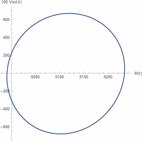
Figure 14. Vout(t) v.s. M(t) of Type A Wien oscillator: fractional memristor with a = 1.25
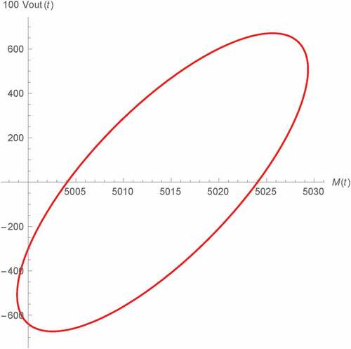
Figure 20. Vout(t) v.s. M(t) of Types C and D Wien oscillator: fractional memristor with a = 1.25
Before proceed further, it is worthy to mention here that it is not surprising that the simulation results of type C and D oscillator are very much similar so that they are coincided as can be seen from the above tables and figures in spite of their different circuit structures. This is because such similarities can also be observed from the conventional memristor based type C and D oscillator as proposed by Talukdar et al. Therefore, it can be stated that the fractional domain generalization inherits the similarities in the results of types C and D memristor-based Wien oscillators.
7. Discussions
At this point, some further discussions on the obtained simulated results should be given. In order to do so, the approximated closed form expression of Vout(t) should be derived. By ignoring the high order terms of (24) and using the linear approximations of 1/M(t) and its integral, Vout(t) of for A and B fractional memristor-based Wien oscillator can be approximately determined by baring (26) in mind as given by (31). On the other hand, that of type C and D counterparts can be obtained with (28) be kept in mind as given by (32). Noted also that X(t) and Y(t) can be respectively given by (33) and (34) and fosc become favr at the asymptotic state.
From (31) to (34), it can be seen that Vout(t) contains sinusoidal term with time increasing magnitude. This explains the asymptotically larger magnitude of Vout(t) as graphically displayed above. By carefully observing these equations, such sinusoidal term which is symbolized by Z(t), can be given as follows
Therefore the aforesaid time increasing magnitude of Z(t) (AZ(t)) can be immediately given by
As a result, we have the following rate of change of AZ(t)
From (37), it has been found that
Since the cosine function is non monotonic, we have found that dAZ(t)/dt is inversely proportional to α due to (38). This explains the above graphically portrayed relationship between the increasing in magnitude of Vout(t) and α.
Moreover, as favr is robust to α as already demonstrated, so does the time at which sustained oscillation is occurred (Tsus). This is because Tsus can be determined given favr and M(t) at t = Tsus, that is, M(Tsus), by using (40) therefore any α related behavior of favr is immediately inherited by Tsus including the robustness to α. Noted also that (40) has been formulated by using (14) with satisfied and keeping in mind that fosc become steady at favr at t = Tsus as the sustained oscillation is occurred
Now some other interesting issues will also be discussed. Firstly, if more degree of freedom is required then we can replace C1 and C2 by the fractional capacitors, that is, C1β and C2γ. Noted that the usage of fractional capacitors in the nonparametric Wien oscillators has been previously presented by Radwan et al. (Radwan, Soliman, & Elwakil, Citation2008). Since we let these fractional capacitors be of incommensurate orders for obtaining maximum degree of freedom, (22) and (26)–(29) become (41)–(45) where and
denote the voltage dropped across C1β and C2γ.
From these equations, it can be seen that more degree of freedom has been obtained as Vout(t) can also be now controlled via β and γ apart from α. As an illustration, we will demonstrate the controlling of Vout(t) of type A oscillator by simply changing β and γ. Such type A oscillator has been chosen due to its higher linearity mentioned above. By using the above fractional capacitor based equations with M(0) = 5 kΩ, C1β = 3.2 μF∙sβ−1 and C2γ = 3.2 μF∙sγ−1, the resulting Vout(t) can be simulated for various combinations of β and γ as depicted in Figures – where α = 1.25 has been assumed as we promote the usage of the fractional memristor with α > 1 due to its many pros. The significant different transient behaviors and steady state magnitudes of Vout(t) can be observed in spite of their same α. This demonstrates the controllability of Vout(t) by using β and γ.
Figure 18. Vout(t) v.s. M(t) of Types C and D Wien oscillator: fractional memristor with a = 0.75
For validation, the comparison with benchmarks simulated by using the SPICE HP memristor model with order of 1.25 have been made as also shown in these figures where the strong agreements, which verify such controllability and also validates our results with other α apart from 1 that has been verified in the previous section, can be observed. Noted that a similar controllability can also be achieved by the oscillator of other types. It should be mentioned here that the order of SPICE HP memristor model which is conventionally 1, can be made nonunity for emulating the fractional memristor by simply let the value of current controlled current source in its schematic be kαi(t)f(x(t)) and replacing the conventional capacitor with the fractional one where such fractional capacitor along with C1β and C2γ can be simply emulated by using the resistive-conventional capacitor network for circuit simulation purpose. This is because the fractional impedance function can be approximately given in term of the conventional rational polynomial impedance function (Matsuda & Fujii, Citation1993), (Oustaloup, Levron, Mathieu, & Nanot, Citation2000), (Valsa & Vlach, Citation2013). However, order of the resulting resistive-capacitor network can be very high for obtaining acceptably low phase ripple within the acceptably wide frequency range (Valsa & Vlach, Citation2013), which is necessary for accurately emulating the fractional capacitor as its phase is ideally constant with respected to the frequency.
Secondly, if nonlinearity near boundaries of the memristive device must also be taken into account, we must assume the nonlinear dopant drift thus another f(x(t)) beside (8) must be applied. The examples of such f(x(t)) are those proposed by Joklecar and Wolf (Joglekar & Wolf, Citation2009), Biolek et al. (Biolek, Biolek, & Biolkova, Citation2009b), Prodomakis et al. (Prodromakis, Peh, Papavassiliou, & Toumazou, Citation2011), etc. Without regarding to any specific f(x(t)), the state space representation of the oscillator of any type can be now given by
If we use the Joklecar’s window function which can be given by (Joglekar & Wolf, Citation2009)
where p ≥ 1 and , the resulting Vout(t) of type A oscillator can be simulated as depicted in Figure where p = 1, α = 1.25, β = γ = 0.95, C1β = 3.2 μF∙sβ−1 and C2γ = 3.2 μF∙sγ−1 have been assumed. Since it can be seen that Vout(t) become eventually distorted, it can be stated such nonlinearity near boundaries causes the oscillator to suffer a nonlinear distortion. For validation, comparison with the order 1.25 SPICE HP memristor model-based benchmark has been made as also shown in these figures where the strong agreements, which verify the above statement and further validates of our results with other α apart from 1, can be observed. It should be mentioned here that the SPICE HP memristor model with Joklecar’s window function has been adopted in this scenario unlike the previous simulations which such model with linear window function has been used as the nonlinear dopant drift has been assumed.
Figure 21. Vout(t) v.s. t of Type A Wien oscillator (ß = 0.95 and γ = 1): fractional memristor with a = 1.25 (line), order 1.25 SPICE HP memristor model (dots)
8. Conclusion
The fractional domain generalization of the memristor-based parametric Wien oscillators by using fractional memristor have been performed in this work. We have found that the effects of α to favr and sustained oscillating condition are insignificant. However, it has been found that α significantly affects Δfosc, the phase difference between M(t) and Vout(t), the asymptotic magnitude of Vout(t) and the difference between such asymptotic value and its early state counterpart. From the analysis results which have been verified by using the SPICE HP memristor model-based simulation, we promote the usage of the fractional memristor with α > 1 due to its many pros and the further generalization by using fractional capacitors if more degree of freedom is desired. We also give a discussion on the effect of nonlinear dopant drift which has been previously ignored by Talukdar et al. (Talukdar et al., Citation2011). Therefore, this research gives a simple, yet effective design methodology of the parametric Wien family and clearly demonstrates an interesting application of the state of the art fractional memristor.
Conflict of Interests
The author declares that there is no conflict of interests regarding the publication of this paper.
Acknowledgements
The author would like to acknowledge Mahidol University, Thailand, for the online database service which is our primary information resource.
Additional information
Funding
Notes on contributors
Rawid Banchuin
Rawid Banchuin received the B.Eng. degree in electrical engineering from Mahidol University, Bangkok, Thailand in 2000, the degree of M.Eng. in computer engineering and Ph.D. in electrical and computer engineering from King Mongkut’s University of Technology Thonburi, Bangkok, Thailand in 2003 and 2008 respectively.
He was with the Department of Electrical Engineering, Rajamangala Institute of Technology, North-Bangkok Campus since 2003. At the present, he is with the Graduated School of Information Technology and Faculty of Engineering, Siam University, Bangkok, Thailand.
Asst. Prof. Dr. Rawid Banchuin is a member of council of engineer (Thailand) and has joined the organizing committee of the international conference on ICT and knowledge engineering, which is jointly organized by IEEE, since 2012. His current research interests include circuit elements with memory, fractance device and fractional order circuits/systems.
Related Research Data
References
- Anusudha, T. A., & Prabaharan, S. R. S. (2018). A versatile window function for linear ion drift memristor model–A new approach. AEU-International Journal of Electronics and Communications, 90, 130–26. doi:10.1016/j.aeue.2018.04.020
- Banchuin, R. (2017). Novel expressions for time domain responses of fractance device. Cogent Engineering, 4(1), 1–28. Retrieved from https://www.cogentoa.com/.1320823
- Banchuin, R. (2018). On the memristances, parameters, and analysis of the fractional order memristor. Active and Passive Electronic Components, 2018, 1–14. doi:10.1155/2018/3408480
- Beyer, W. H. (2018). Handbook of Mathematical Science: 0. Florida: CRC press.
- Biolek, D., Biolek, Z., & Biolkova, V. (2009a, August). SPICE modeling of memristive, memcapacitative and meminductive systems. In 2009 European Conference on Circuit Theory and Design, Antalya, Turkey (pp. 249–252). doi: 10.1109/ECCTD.2009.5274934
- Biolek, D., Biolek, Z., Biolkova, V., & Kolka, Z. (2014). Modeling of TiO2 memristor: From analytic to numerical analyses. Semiconductor. Science and Technology, 29(12), 125008.
- Biolek, Z., Biolek, D., & Biolkova, V. (2009b). SPICE model of memristor with nonlinear dopant drift. Radioengineering, 18(2), 210–214. Retrieved from https://www.radioeng.cz/fulltexts/2009/09_02_210_214.pdf
- Charef, A. (2006). Analogue realisation of fractional-order integrator, differentiator and fractional PIλDµ controller. IEE Proceedings-Control Theory and Applications, 153(6), 714–720. doi:10.1049/ip-cta:20050019
- Chua, L. O. (1971). Memristor-the missing circuit element. IEEE Transactions on Circuit Theory, 18(5), 507–519. Retrieved from https://ieeexplore.ieee.org/abstract/document/1083337/
- Dorčák, Ľ., Terpák, J., Petráš, I., & Dorčáková, F. (2007). Electronic realization of the fractional-order systems. Acta Montanistica Slovaca, 12(3), 231–237. Retrieved from http://actamont.tuke.sk/
- Fouda, M. E., & Radwan, A. G. (2013). On the fractional-order memristor model. Journal of Fractional Calculus and Applications, 4(1), 1–7. Retrieved from http://www.fcaj.webs.com/
- Fouda, M. E., & Radwan, A. G. (2015). Fractional-order memristor response under dc and periodic signals. Circuits, Systems, and Signal Processing, 34(3), 961–970. doi:10.1007/s00034-014-9886-2
- Gómez-Aguilar, J. F., Rosales-García, J. J., Bernal-Alvarado, J. J., Córdova-Fraga, T., & Guzmán-Cabrera, R. (2012). Fractional mechanical oscillators. Revista Mexicana De Física, 58(4), 348–352. Retrieved from http://rmf.smf.mx/
- Jeong, H. Y., Lee, J. Y., Choi, S. Y., & Kim, J. W. (2009). Applied Physics Letters. Microscopic Origin of Bipolar Resistive Switching of Nanoscale Titanium Oxide Thin Films, 95(16), 162108. doi:10.1063/1.3251784
- Jesus, I. S., MacHado, J. T., & Cunha, J. B. (2008). Fractional electrical impedances in botanical elements. Journal of Vibration and Control, 14(9–10), 1389–1402. doi:10.1177/1077546307087442
- Joglekar, Y. N., & Wolf, S. J. (2009). The elusive memristor: Properties of basic electrical circuits. European Journal of Physics, 30(4), 661. Retreived from https://iopscience.iop.org/article/10.1088/0143-0807/30/4/001
- Kilbas, A. A. A., Srivastava, H. M., & Trujillo, J. J. (2006). Theory and applications of fractional differential equations (Vol. 204). Amsterdam: Elsevier Science Limited.
- Kim, H., Sah, M. P., Yang, C., Cho, S., & Chua, L. O. (2012). Memristor emulator for memristor circuit applications. IEEE Transactions on Circuits and Systems I: Regular Papers, 59(10), 2422–2431. doi:10.1109/TCSI.2012.2188957
- Komine, V., Galliou, S., & Makarov, A. (2003). A parametric quartz crystal oscillator. IEEE Transactions on Ultrasonics, Ferroelectrics, and Frequency Control, 50(12), 1656–1661. doi:10.1109/TUFFC.2003.1256305
- Kozma, R., Pino, R. E., & Pazienza, G. E. (2012). Advances in Neuromorphic Memristor Science and Applications. Berlin/Heidelberg: Springer Science & Business Media.
- Krishna, B. T., Reddy, K. V. V. S., & Santa Kumari, S. (2008). Time domain response calculations of fractance device of order 1/2. Journal of Active and Passive Electronic Devices, 3(3), 355–367. Retrieved from http://www.oldcitypublishing.com/journals/japed-home/
- Matsuda, K., & Fujii, H. (1993). H (infinity) optimized wave-absorbing control-Analytical and experimental results. Journal of Guidance, Control, and Dynamics, 16(6), 1146–1153. Retrieve from: https://arc.aiaa.org/doi/10.2514/3.21139
- Matušů, R. (2011). Application of fractional order calculus to control theory. International Journal of Mathematical Models and Methods in Applied Sciences, 5(7), 1162–1169. Retrieved from https://www.researchgate.net
- Mouttet, B. L. (2007). U.S. Patent No. 7,302,513. Washington, DC: U.S. Patent and Trademark Office.
- Olumodeji, O. A., & Gottardi, M. (2017). Arduino-controlled HP memristor emulator for memristor circuit applications. Integration, 58, 438–445. doi:10.1016/j.vlsi.2017.03.004
- Oustaloup, A., Levron, F., Mathieu, B., & Nanot, F. M. (2000). Frequency-band complex noninteger differentiator: Characterization and synthesis. IEEE Transactions on Circuits and Systems I: Fundamental Theory and Applications, 47(1), 25–39. doi:10.1109/81.817385
- Pershin, Y. V., & Di Ventra, M. (2010). Experimental demonstration of associative memory with memristive neural networks. Neural Networks, 23(7), 881–886. doi:10.1016/j.neunet.2010.05.001
- Podlubny, I. (2002). Geometric and physical interpretation of fractional integration and fractional differentiation. Fractional Calculus & Applied Analysis, 5(4), 367–386. Retrieved from https://arxiv.org/pdf/math/0110241.pdf
- Prodromakis, T., Peh, B. P., Papavassiliou, C., & Toumazou, C. (2011). A versatile memristor model with nonlinear dopant kinetics. IEEE Transactions on Electron Devices, 58(9), 3099–3105. doi:10.1109/TED.2011.2158004
- Radwan, A. G., & Elwakil, A. S. (2012). An expression for the voltage response of a current‐excited fractance device based on fractional‐order trigonometric identities. International Journal of Circuit Theory and Applications, 40(5), 533–538. doi:10.1002/cta.760
- Radwan, A. G., Soliman, A. M., & Elwakil, A. S. (2008). Design equations for fractional‐order sinusoidal oscillators: Four practical circuit examples. International Journal of Circuit Theory and Applications, 36(4), 473–492. doi:10.1002/cta.453
- Radwan, A. G., Zidan, M. A., & Salama, K. N. (2010a, December). On the mathematical modeling of memristors. In 2010 International Conference on Microelectronics (pp. 284–287). Cairo: IEEE. doi: 10.1109/ICM.2010.5696139
- Radwan, A. G., Zidan, M. A., & Salama, K. N. (2010b, August). HP memristor mathematical model for periodic signals and DC. In 2010 53rd IEEE International Midwest Symposium on Circuits and Systems (pp. 861–864). Seattle, WA: IEEE. doi: 10.1109/MWSCAS.2010.5548670
- Sabatier, J. A. T. M. J., Agrawal, O. P., & Machado, J. T. (2007). Advances in fractional calculus (Vol. 4, No. 9). Dordrecht: Springer. doi:10.1007/978-1-4020-6042-7
- Sah, M. P., Yang, C., Kim, H., & Chua, L. (2012). A voltage mode memristor bridge synaptic circuit with memristor emulators. Sensors, 12(3), 3587–3604. doi:10.3390/s120303587
- Strukov, D. B., Snider, G. S., Stewart, D. R., & Williams, R. S. (2008). The missing memristor found. Nature, 453(7191), 80–83. doi:10.1038/nature06932
- Talukdar, A., Radwan, A. G., & Salama, K. N. (2011). Generalized model for memristor-based Wien family oscillators. Microelectronics Journal, 42(9), 1032–1038. doi:10.1016/j.mejo.2011.07.001
- Tang, C., You, F., Cheng, G., Gao, D., Fu, F., & Dong, X. (2009). Modeling the frequency dependence of the electrical properties of the live human skull. Physiological Measurement, 30(12), 1293. doi:10.1088/0967-3334/30/12/001
- Valsa, J., & Vlach, J. (2013). RC models of a constant phase element. International Journal of Circuit Theory and Applications, 41(1), 59–67. doi:10.1002/cta.785
- Vinagre, B. M., & Feliu, V. (2007). Optimal fractional controllers for rational order systems: A special case of the Wiener-Hopf spectral factorization method. IEEE Transactions on Automatic Control, 52(12), 2385–2389. doi:10.1109/TAC.2007.910728
- Yang, C., Cho, S., Sah, M. P., Kim, H., & Jung, K. S. (2012, August). Memristor emulator with off-the-shelf solid state components for memristor application circuits. In 2012 13th International Workshop on Cellular Nanoscale Networks and their Applications (pp. 1–5). Turin: IEEE. doi: 10.1109/CNNA.2012.6331432