
Abstract
Industrially, unprocessed crude oil has little or no value. Hence, there is need for a country to have operational petroleum refineries. According to the Nigerian National Petroleum Corporation annual bulletin, it is expected to have a total refining capacity of 445,000 barrels of oil per day from Nigeria’s four conventional refineries. However, the country still records scarcity of refined products as none of the refineries can boast of working above 60% of its design capacity. In an attempt to provide, a solution to the worsening scenario above, modular refineries setup at strategic positions within the country can help. This will boost refining capacity. Although different modular topping refinery configurations exist, this paper examines the simple, pre-flash and the pre-flash pump around reflux scheme in terms of maximum product yield using the Niger Delta Petroleum Resources, Bonny Light, Bonny Medium, Brass and Qua Iboe crude assay. Crude oil characterization using HYSYS® ASPEN was done based on their true boiling points to determine the maximum liquid volume fraction of the different distillates. Simulations of the different crude assay were carried out on the different topping refinery configurations highlighting the variation between characterized and simulated volumetric cuts. The result shows that Niger Delta Petroleum Resources crude will favour the production of liquefied petroleum gas, light naphtha, and diesel. Bonny medium crude will favour the production of gas oil and residue oil while qua iboe and brass will favour the production of kerosene and heavy naphtha, respectively. The best scheme for different distillates was also determined.
Keywords:
PUBLIC INTEREST STATEMENT
The setting up of modular crude oil refineries is a feasible solution to countries experiencing low refining output from their conventional refineries. With the use of HYSYS® ASPEN, this paper examines the simulation of three different schemes of modular topping refinery for five types of Nigeria crude oil. The results which shows the effective parameters for peak-distilled products will be useful to refiners and private investors for decision-making.
1. Introduction
Though Nigeria has a total design refining capacity of 445,000 bopd (barrel of oil per day) expected from its conventional refineries, low refining output is recorded leading to scarcity of various-refined products within the country. Little success stories have also been achieved in encouraging private investors into the petroleum downstream sector. Aside the large money spent on the importation of refined products, the sub-optimal performance of the Nigerian refineries has also led to high rate of unemployment, under-utilization of our raw crude oil, bad reputation among other oil-producing countries and most importantly deprivation of feed to its petrochemical industry (Mamudu, Igwe, & Okonkwo, Citation2016; Okoro, Dosunmu, Igwilo, Anawe, & Mamudu, Citation2017). The energy crisis is a real challenge to human society, since oil sources in the world are declining, in addition, the growing consumption of fossil resources has brought huge impact on the global climate and environment. (Aligolzadeh, Jebreili, & Mohammadikhah, Citation2015; Zhao et al., Citation2017).
In an attempt to provide solutions to the sad scenario above, the country is left with the options of establishing more conventional refineries, legalizing the illegal refineries, swapping of raw crude with refined products from other countries or setting up of modular refineries within the country. The establishment of more conventional refineries for conversion of oil into various products (Nwanya & Isi, Citation2018) seems to be moving at snail speed while the swapping of crude oil for refined products from other countries serves only as a temporary solution. The legalization of the illegal refineries brings mixed feelings among citizens as it seems to encourage theft coupled with high emission of poisonous gases (Odunlami, Elehinafe, Pearl, Abatan, & Mamudu, Citation2018), which leaves the country with the most feasible option of setting up modular refineries at strategic locations within the country. In Nigeria, setting up modular refineries will help to: support the low performance of the existing refineries, eradicate the shortage of petroleum products, minimize over reliance on imported petroleum products, remove the need for subsidy, encourage private investors since the start off capital is small in comparison to a conventional refinery and ensure optimal use of our resources which in turn has a multiplier effect on the economy (Mamudu et al., Citation2019).
1.1. The modular refinery era
The concept “modular refinery” is not new, as it has earlier been used in the early forties, later re-surfacing in the seventies where a one skid portable crude topping unit for the production of straight-run gasoline, diesel oil, and heavy fuel was developed (Hogan, Citation1976). It is globally applied where: crude oil and a ready market are available but low refining capacity is recorded, a reduction in the cost of moving the crude oil from a source of production to remote refineries is needed (Hogan, Citation1976) or there is a need to setup a refinery which can easily be hidden or taken down (Duncan & Knox, Citation1991). It can be applied to process any kind of crude (Lourenco & Murphy, Citation2011) or even used for bitumen processing (Berry & Luhan, Citation2008).
Modular refineries, which are defined as conventional refineries constructed in fragmented ways (Brown, Maxwell, Rick, & Shumway, Citation2003) or big refineries in miniature form (Igwe, Citation2014), are currently found in Australia, Cairo, Cameroun, Congo, Egypt, Gabon, Guinea, Indonesia, Niger Republic, Russia, Zambia, Kurdistan, Senegal and Siberia (Adoyi, Citation2014). Nigeria also has a 1000 bopd modular topping plant located at Ogbelle field fully owned by the Niger Delta Petroleum Resources. The University of Port-Harcourt also houses a modular topping laboratory where crude distillation experiment under both atmospheric and vacuum condition can be performed. It comes in different packages with increasing degree of sophistication performing the three basic purposes of crude oil refining; separation, conversion, and treatment. The different configurations include: Topping (Atmospheric Distillation) Unit, Hydro-Skimming Unit, Vacuum Distillation Added Unit, and the Full Conversion Unit.
1.1.1. Modular topping refinery
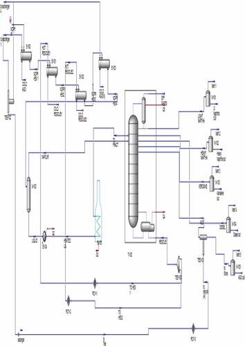
The topping unit separates the crude oil into fractions or distillates based on their difference in boiling points. It is used for the production of diesel and/or kerosene while naphtha, fuel gas and the residue serve as its by-products. The crude oil as shown in Figure is pre-heated through series of heat exchanger networks both before and after the de-salter, which helps to remove water-containing salts. The desalting stage remains optional depending on the quantity of salt in the crude. The preheaters makes use of hot vapours streams from the main column condenser, the pump-around (PA) circuit streams, and the distilled products (Bagajewicz & Ji, Citation2001).The preheated crude is further heated to a temperature range of 340–370°C for the required percentage of vaporization.
1.1.2. Evolution of the crude distillation column
As shown in Figure , a modular topping refinery has an atmospheric distillation column, heat exchanger network, and furnace as its main equipment. Products from this simplified version do not meet specifications, since products are not stripped of any light components. Miller and Osborne (Citation1938) proposed the introduction of side strippers popularly known as TYPE U distillation scheme. The side strippers use either steam or distilled hot residue oil as a source of heating.
Figure 1. A modular crude oil topping refinery (Errico, Tola, & Mascia, Citation2009)
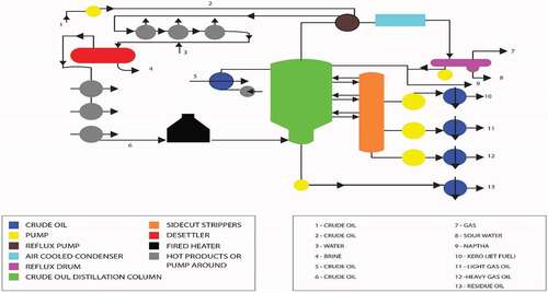
Watkins (Citation1979) later proved that although this design is feasible, increasing vapour and liquid traffic will occur within the column since all heat within the system is taken care of by only the condenser. Therefore, the diameter of the top section of the column has to be large enough to accommodate this traffic (Bagajewicz, Citation1998). Watkins (Citation1979) made an improvement on TYPE U by removing some of the heat below the top tray, which led to the introduction of pump around and pump back refluxes. Pump back reflux scheme (TYPE R) refers to liquid being withdrawn from a tray, cooled and pumped back to the column at several points below the withdrawal point. Pump around reflux scheme (TYPE A) which has become the prominent design in the industry uses an externally circulated and cooled stream for the partial removal of heat. Liquid is withdrawn, cooled and pump backed above the withdrawal tray.
Although the different modular topping configurations are highlighted in details above, this paper examines the simple, pre-flash and the pre-flash pump around reflux scheme in terms of maximum product yield using NDPR, Bonny Light, Bonny Medium, Brass and Qua Iboe crude assay.
2. Methods
The method adopted for this study follows the sequence below:
Oil characterization of the different crude assay (NDPR, Bonny Light, Bonny Medium, Brass and Qua Iboe) using HYSYS® ASPEN Simulator version 8.6 was done based on their true boiling point to determine the liquid volume fraction of the different distillates that can be gotten from crude oil at an ideal condition.
Simulations of the different crude assay were carried out on the different modular configurations/designs (simple distillation, pre-flash, pre-flash with pump around reflux) with different operating parameters when converged.
Determination of the variation between characterized and simulated volumetric cuts in barrels per day.
Analysis to determine the best scheme for different distillates (Off Gas, Naphtha, Kerosene, Diesel and Atmospheric residue).
3. Results and discussion
3.1. Liquid volume fraction at ideal condition
3.1.1. Bonny light characterization
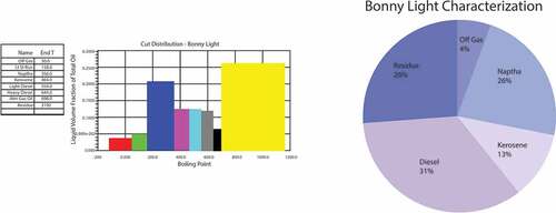
Bonny light crude characterized based on its true boiling points produces 0.039 m3, 0.05 m3,0.21 m3,0.13 m3,0.126 m3, 0.125 m3, 0.065 m3, and 0.27 m3 liquid volume fraction of off gas, light naphtha, heavy naphtha, kerosene, light diesel, heavy diesel, AGO and residue, respectively, as shown in Figure . The values in percentage form are 4% off gas, 26% naphtha, 13% kerosene, 30% diesel and 27% atmospheric residue of the total liquid volume fraction at an ideal condition.
Figure 2. Bonny light characterization
3.1.2. Bonny medium characterization
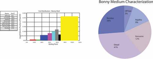
Bonny medium crude characterized based on its true boiling points produces 0.02 m3, 0.01 m3, 0.085 m3, 0.12 m3, 0.14 m3, 0.175 m3, 0.1 m3, and 0.365 m3 liquid volume fraction of off-gas, light naphtha, heavy naphtha, kerosene, light diesel, heavy diesel, AGO and residue, respectively, as shown in Figure . These values in percentage are 2%, 9%, 12%, 41% and 36% off gas, naphtha, kerosene, diesel and atmospheric residue, respectively, of the total liquid volume fraction.
Figure 3. Bonny medium characterization
3.1.3. Qua iboe characterization
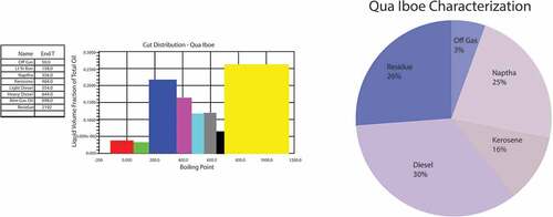
Qua Iboe characterization produces 0.035 m3, 0.023 m3, 0.225 m3, 0.16 m3, 0.12 m3, 0.06 m3 and 0.265 m3 liquid volume fraction of off-gas, light naphtha, heavy naphtha, kerosene, light diesel, heavy diesel, AGO, and residue, respectively, as shown in Figure . Expressed in percentage forms, the distillate volume fraction in the reservoir or its recoverability factors are 3%, 25%, 16%, 30% and 26% off gas, naphtha, kerosene, diesel, and atmospheric residue, respectively.
Figure 4. Qua iboe crude characterization
3.1.4. Brass crude characterization
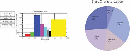
Brass crude characterized based on its true boiling points produces 0.021 m3, 0.06 m3, 0.28 m3, 0.155 m3, 0.13 m3, 0.09 m3, 0.0496 m3, and 0.22 m3 liquid volume fraction of off-gas, light naphtha, heavy naphtha, kerosene, light diesel, heavy diesel, AGO and residue, respectively, as shown in Figure . At an ideal condition, a maximum value of 2% off gas, 34% Naphtha, 15% Kerosene, 27% diesel and 22% atmospheric residue of the total liquid volume fraction will be produced.
Figure 5. Brass crude characterization
3.1.5. NDPR crude characterization
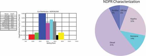
NDPR crude characterized based on their true boiling points produces 0.058 m3, 0.078 m3, 0.25 m3, 0.14 m3, 0.19 m3, 0.165 m3, 0.06 m3, and 0.07 m3 liquid volume fraction of off-gas, light naphtha, heavy naphtha, kerosene, light diesel, heavy diesel, AGO and residue, respectively, as shown in Figure . At an ideal condition, a maximum value of 6% off gas, 33% Naphtha, 14% Kerosene, 41% diesel and 7% atmospheric residue of the total liquid volume fraction will be produced.
Figure 6. NDPR characterization
3.2. Simulation of different modular topping refinery configurations
3.2.1. Design one-simple distillation process
Figure shows the characterization of the crude oil feed using the simple distillation process. This scheme consists of the pre-heaters, heaters, distillation column, splitter, and distilled products storage tanks. Important parameters of these units are shown in Table .
Figure 7. Simple distillation process
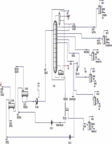
Table 1. Parameters for storage tank and distillation column (simple distillation)
Table 2. Parameters for distillation column (pump around reflux)
3.2.2. Design two- pre- flash with pump around reflux
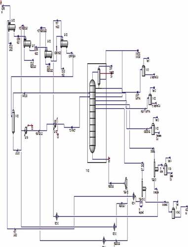
The addition of a pre-fractionation column is to avoid unnecessarily heating of light naphtha, which are condensed separately. Pump around reflux scheme, which has become the prominent design in the industry uses an externally circulated and cooled stream for the partial removal of heat. Liquid is withdrawn, cooled and pump backed above the withdrawal tray. Important parameters for this paticular design is shown in table 2 while figure 8 shows the characterization of the crude oil using preflash with pump around reflux model.
Figure 8. Pre-flash pump-around reflux
3.2.3. Design three: pre-flash without pump around reflux
This scheme as shown in figure 9 shows the intending effect to avoid unnecessary heating of light components in the furnace, injecting them at an appropriate tray in the column for further fractionation.
Figure 9. Pre-flash without pump-around reflux
3.3. Variation between characterized and simulated valued for different products
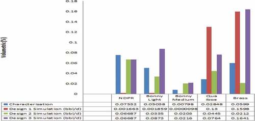
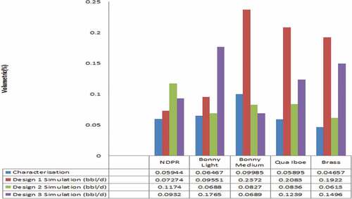
3.3.1. Off-gas
Figure shows that under normal distillation condition, NDPR crude should produce more volume of off-gas or liquefied petroleum gas (LPG) while bonny medium should give the least. The use of pre-flash scheme will favour LPG production for NDPR and bonny light crude. Pre-flash pump around favors the production of off-gas for bonny medium, qua Iboe and brass crude.
Figure 10. Off gas yield
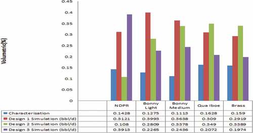
3.3.2. Light naphtha
Figure illustrates that NDPR crude generally favours the production of light naphtha while qua iboe gives the least. Both pre-flash and pre-flash pump-around favour the production of light naphtha for NDPR crude. Pre-flash with pump around is ideal for bonny light, bonny medium, qua Iboe and brass crude oil.
Figure 11. Light naphtha yield
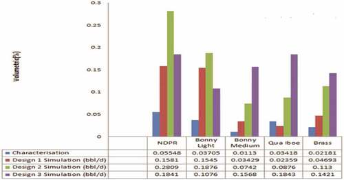
3.3.3. Heavy naphtha
Brass crude favours the production of heavy naphtha when compared to the rest while bonny medium produces the least volume as shown in Figure . The use of pre-flash favours the production of heavy naphtha for NDPR, bonny light, bonny medium and qua iboe crude. Pre-flash pump-around favours the production of heavy naphtha for brass crude.
Figure 12. Heavy naphtha yield
3.3.4. Kerosene
Figure shows that qua iboe crude generally favours the production of kerosene while bonny medium will give the least amount under distillation processes. The use of pre-flash with pump-around favours kerosene production for NDPR crude oil, simple distillation for both bonny light and medium crude while pre-flash for qua iboe and brass crude.
Figure 13. Kerosene yield
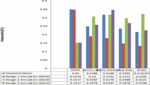
3.3.5. Diesel
NDPR crude favours the production of diesel when compared to the other crude while brass will produce the least amount. Figure shows that pre-flash scheme favours the production of diesel for bonny light, qua iboe and brass crude while pre-flash with pump-around favours the production of diesel for bonny medium crude. Simple distillation favours NDPR crude.
Figure 14. Diesel yield
3.3.6. Gas oil
As shown in Figure , bonny medium crude favours the production of gas oil when compared to the rest crude with brass crude being the least. While pre-flash scheme with pump-around favours the production of gas oil for NDPR crude, simple distillation favours bonny light, bonny medium, qua iboe and brass crude for gas oil production.
Figure 15. Gas oil yield
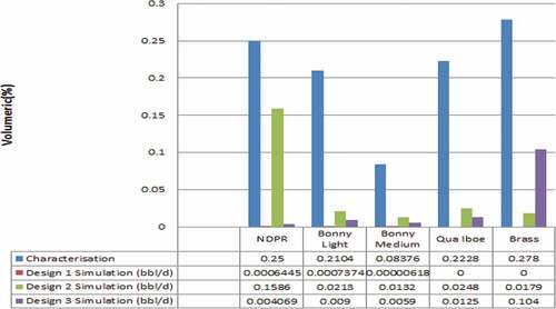
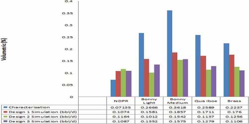
3.3.7. Residue oil
As shown in Figure , bonny medium crude has more residue oil while NDPR crude produces the least. Although pre-flash scheme favours residue oil production for NDPR crude, simple distillation scheme favours the production of residue for others.
Figure 16. Residue yield
4. Conclusion
The When NDPR, bonny light, bonny medium, qua iboe and brass crude oil are individually weighed within simple, pre-flash and pre-flash pump-around modular topping refinery schemes the following conclusions can be drawn:
NDPR crude favours the production of LPG, light naphtha and diesel
Bonny medium crude favours the production of gas oil and residue oil
Qua Iboe and brass favour the production of kerosene and heavy naphtha, respectively
Simple distillation and pre-flash favour the production of diesel and residue oil, respectively, for NDPR crude.
Simple distillation scheme favours the production of gas oil and diesel oil for bonny light, bonny medium, qua iboe and brass crude.
Pre-flash favours the production of LPG for both NDPR and bonny light crude.
Pre-flash pump-around favours the production of LPG for bonny medium, qua iboe and brass crude.
Pre-flash with pump-around favours the production of light naphtha for all crude assays considered.
Pre-flash scheme favours the production of heavy naphtha for NDPR, bonny light, bonny medium and qua iboe crude.
Pre-flash pump-around favours the production of heavy naphtha and kerosene for brass and NDPR crude, respectively.
Simple distillation favours the production of kerosene for bonny light and medium crude
Pre-flash scheme favours the production of kerosene for qua iboe and brass crude.
Nomenclature
| BOPD | = | Barrel of Oil per Day |
| °C | = | Degree Celsius |
| Kpa | = | Kilopascal |
| LPG | = | Liquefied Petroleum Gas |
| m | = | Meter |
| mm | = | Millimetres |
| NDPR | = | Niger Delta Petroleum Resources |
| PA | = | pump-around |
| % | = | Percentage |
Cover Image
Source: Author.
Acknowledgements
The authors would like to thank the management of Covenant University, Nigeria for providing an enabling environment for this research.
Additional information
Funding
Notes on contributors
Angela O. Mamudu
Angela O. Mamudu holds a bachelor’s degree in Chemical Engineering from Covenant University, a master’s degree in Oil and Gas Engineering from the University of Aberdeen Scotland and a doctorate degree in Chemical Engineering (Crude Oil Refining) from World Bank African Centre of Excellence in Oilfield Chemical Research, University of Port- Harcourt. She is currently a lecturer in Chemical Engineering Department at Covenant University, Nigeria. Her research interest includes Process Optimization, Plant Design, Petroleum Refining and Petrochemicals.
Related Research Data
References
- Adoyi, O. B. (2014). Design and Fabrication of Crude Distillation Unit Components for a Mini Petroleum Refinery. MS thesis. Zaira: Ahmadu Bello University.
- Aligolzadeh, H., Jebreili, J. A., & Mohammadikhah, R. (2015). CFD analysis of hot spot formation through a fixed bed reactor of Fischer-Tropsch synthesis. Cogent Engineering, 2(1), 1006016. doi:10.1080/23311916.2015.1006016
- Bagajewicz, M. (1998). The design flexibility of crude atmospheric fractionation units. Chemical Engineering Communications, 166, 111–17. doi:10.1080/00986449808912383
- Bagajewicz, M., & Ji, S. (2001). Rigorous procedure for the design of conventional atmospheric crude fractionation units. Part1: America Chemical Society Journal, 40(2), 617–626. doi:10.1021/ie000302+
- Berry, A. L., & Luhan, K. J. (2008). Module supply chain. United State Patent No.8428870B2.
- Brown, K. B., Maxwell, B. L., Rick, R. V., & Shumway, M. D. (2003). Modular oil refinery. United State Patent No. WO2003031012A1.
- Duncan, J. W., & Knox, L. (1991). Overland petroleum processor. United State Patent No. 4983259.
- Errico, M., Tola, G., & Mascia, M. (2009). Energy saving in a crude distillation Unit by pre-flash implementation. Applied Thermal Engineering, 29(8–9), 1642–1647. doi:10.1016/j.applthermaleng.2008.07.011
- Hogan, J. W. (1976). Mobile refinery. United State Patent No. 3953298.
- Igwe, G. (2014, October 10). Modular refineries will address perennial shortage of petroleum products. Business news, September 8. Retrieved from http://businessnews.com.ng/2014/09/08/modular-refineries-will-address-perennial-shortage-petroleum-products-igwe/
- Lourenco, J. P., & Murphy, J. G. (2011). Upgrading heavy oil with modular units. United State Patent 0162999A1.
- Mamudu, O. A., Igwe, G. J., & Okonkwo, E. (2016). Performance evaluation of the Nigeria petrochemical industry: Reliability of the bag filter in carbon black production. Ewemen Journal of Petrochemical Research and Innovation, 1, 7–17.
- Mamudu, O. A., Okoro, E., Igwilo, K., Olabode, O., Elehinafe, F., & Odunlami, O. (2019). Challenges and prospects of converting Nigeria illegal refineries to modular refineries. The Open Chemical Engineering Journal, 13(1), 1–6. doi:10.2174/1874123101913010001
- Miller, W., & Osborne, H. (1938). The science of petroleum (Vol. 2). London: Oxford University Press.
- Nwanya, S. C., & Isi, C. K. (2018). Inventory cost framework for managing the petroleum product reorder point and order quantity policies. Cogent Engineering, 5(1), 1558475. doi:10.1080/23311916.2018.1558475
- Odunlami, O. A., Elehinafe, F. B., Pearl, A. A., Abatan, O. G., & Mamudu, A. O. (2018). Assessment of carbon monoxide emission from different brands of split air-conditioners. International Journal of Mechanical Engineering and Technology, 9(9), 655–662.
- Okoro, E. E., Dosunmu, A., Igwilo, K., Anawe, P. A. L., & Mamudu, O. A. (2017). Economic advantage of in- country utilization of Nigeria crude oil. Open Journal of Yangtze Gas and Oil, 2, 226–236. doi:10.4236/ojogas.2017.24018
- Watkins, R. N. (1979). Petroleum refinery distillation. Book Division. Houston: Gulf Publishing Company.
- Zhao, Y., Xu, Q., Fu, Y., Yin, L., Wan, X. L., & Zhu, J. B. (2017). Catalytic pyrolysis of dimethyl carbonate to aromatic hydrocarbons. Cogent Engineering, 4(1), 1403540. doi:10.1080/23311916.2017.1403540